
In order to simplify soldering work and improve their quality, a simple temperature controller for a soldering iron tip may come in handy for a home master or a radio amateur. It is such a regulator that the author decided to collect for himself.
For the first time, the circuit of such a device was noticed by the author in the magazine "Young Technician" of the early 80s. According to these schemes, the author has collected several instances of such regulators and still uses them.
To assemble the soldering iron tip temperature control device, the author needed the following materials:
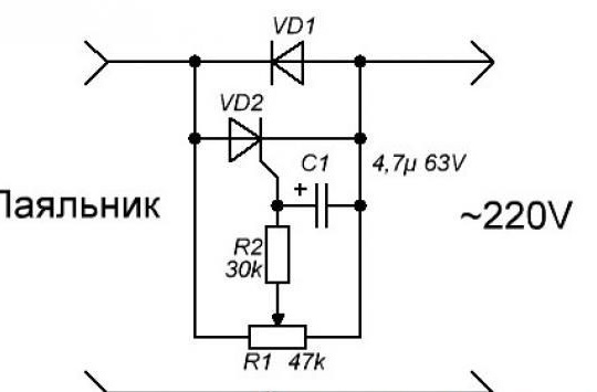
1) diode 1N4007, although any other one is suitable for which a current strength of 1 A and a voltage of 400-60 V are acceptable
2) thyristor KU101G
3) an electrolytic capacitor 4.7 microfarad whose operating voltage is from 50 V to 100 V
4) a resistor of 27 - 33 kOhm, whose power is from 0.25 to 0.5 watts
5) variable resistor 30 or 47 kOhm SP-1 with a linear characteristic
6) power supply housing
7) a pair of connectors with holes for pins with a diameter of 4 mm
Description of the manufacture of a device for regulating the temperature of a soldering iron tip:
In order to better understand the device diagram, the author drew how parts are placed and interconnected.
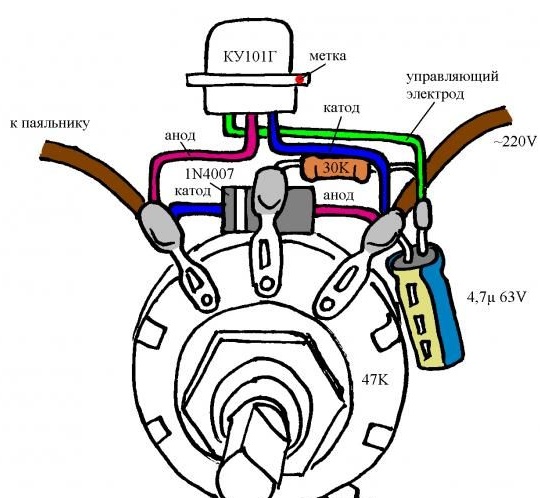
Before starting the assembly of the device, the author isolated and molded the conclusions of the parts. About 20 mm long tubes were put on the thyristor terminals, and 5 mm long tubes on the resistor and diode terminals. To make it more convenient to work with the findings of the parts, the author suggested using colored PVC insulation, which can be removed from any suitable wires, and then attached to heat shrink. Further, using the drawing and photographs as a visual aid, it is necessary to carefully bend the conductors and at the same time not damage the insulation. Then all the parts are attached to the terminals of the variable resistor, while combining in a circuit that contains four soldering points. The next step is to conduct the conductors of each of the components of the device into the holes on the terminals of the variable resistor and gently solder. After which the author shortened the conclusions of the radioelements.

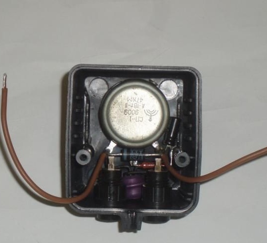
Then the author connected the conclusions of the resistance, the thyristor control electrode and the positive capacitor wire and fixed them with a soldering iron. Since the thyristor case is an anode, the author decided to isolate it for safety.
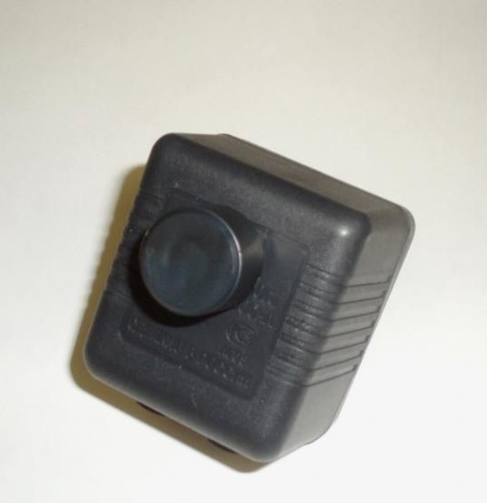
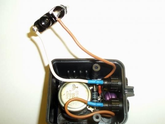
To give the design a finished look, the author used the case of the power supply with a power plug. For this, a hole was drilled on the upper edge of the housing. The diameter of the hole was 10 mm. The threaded part of the variable resistor was installed in this hole and fixed with a nut.
To connect the load, the author used two connectors with holes for pins with a diameter of 4 mm. To do this, the centers of the holes were marked on the casing, the distance between which is 19 mm, and connectors were installed in the drilled holes with a diameter of 10 mm, which the author also fixed with nuts. Further, the author connected the plug of the housing to the assembled circuit and output connectors, and protected the soldering spots using heat shrink.
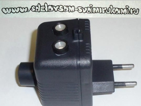
Then the author picked up a suitable size handle made of insulating material of the desired shape and size, in order to cover it with both the axle and the nut.
Then the author assembled the case and securely fixed the knob.
Then he started testing the device. As a load for testing the regulator, the author used an incandescent lamp of 20-40 watts. It is important that when the handle is rotated, the lamp brightness changes quite smoothly. The author managed to achieve a change in the brightness of the lamp from half to full heat. Thus, when working with soft solders, for example POS-61, using an EPSN 25 soldering iron, 75% of the power is enough for the author. In order to obtain such indicators, the control knob should be located approximately in the middle of the stroke.
The author recalls that since all the elements of this system have a voltage of 220 volts from the mains, it is very important to observe all necessary safety measures when working with the device.