» Electronics »Wall clock watering timer

Wall Clock Watering Timer


For those who have country the plot, and especially the greenhouse, will be simply irreplaceable to make just such homemade. This device is designed to automatically irrigate the site at a given time, and it can be connected to any crane with any throughput. This provides significant advantages over factory timers.

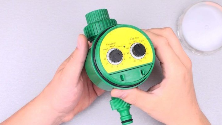
The author uses drip irrigation, for which water comes from a large tank. The purchased timer was never able to provide a sufficient amount of water to the irrigation system, since it is designed for high pressure.

Materials and tools for homemade:
- ordinary wall clocks (arrow);
- reed switches and magnets to them (total reed switch 3 and 2 magnets);
- three batteries;
- 2 buttons are required to create manual control (if necessary);
- transistor IRLML6404 (or other P-channel logic) - if the rain sensor is not used, you can not put it;
- three output mechanical crane CWX-15Q CR02 (or another);
- wires, soldering iron, glue and more.

Water timer manufacturing process:

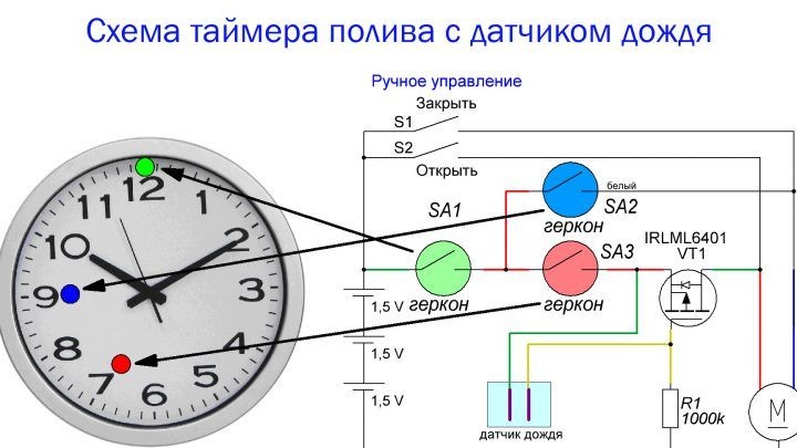
Step one. Scheme and principle of operation
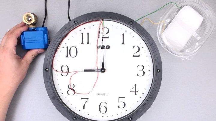
The device works very simply. On the hands of the clock are magnets that interact with the reed switches, closing, then opening the contacts. In total, three pieces are used for the reed switch, so that you can set the timer by minutes and hours. Well, then everything is connected as in the diagram.

Step Two Connection of reed switches and electrovalve
On the hour and minute hands you need to glue small neodymium magnets. Reed switches are installed on the dial itself, they can also be glued. When the magnet approaches the reed switch, the contacts in the reed switch will be closed, and then the power will be supplied to the control transistors.

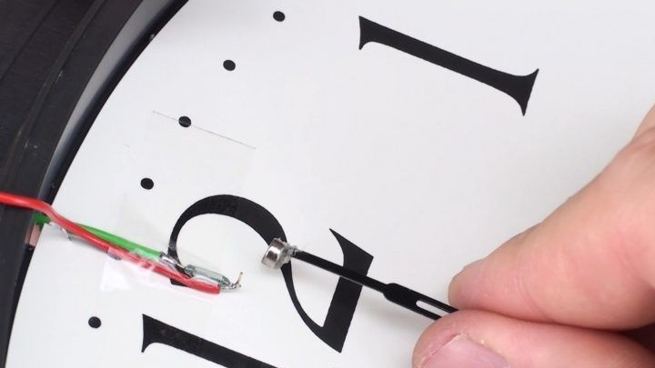
As an example, the author's reed switches are installed on the numbers 7, 9 and 12 hours. Provided that if the minute hand is opposite the number 12, and the hour hand opposite the number 7 hours, the transistor will receive voltage. Well, then the transistor opens and passes current to the solenoid valve, thereby opening it. This is provided that the rain sensor has not detected high humidity. If it rains, the valve will not open.

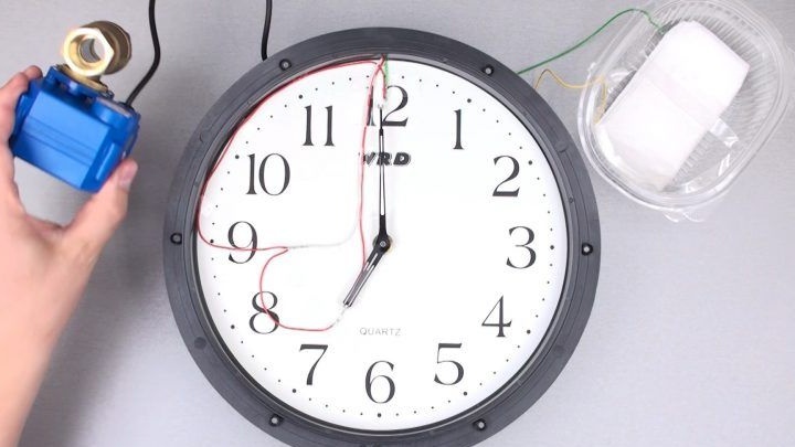
When the arrows stand at the numbers 9 and 12, the electric valve will close and watering will end.

Step Three How to make a rain sensor
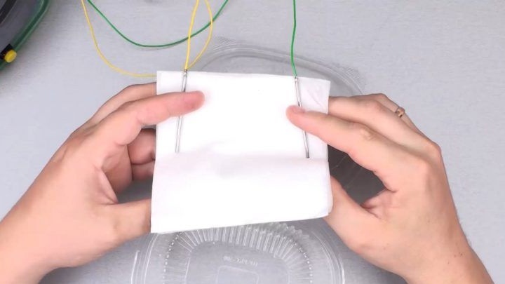
The rain sensor, if necessary, is very simple to make. It is very primitive and is assembled from two electrodes, a napkin and a pinch of salt.When it rains, the wipe gets wet, the contacts close and the transistor closes. Then, when the cloth dries in the sun, the transistor will open again.

To learn more about how the device works, see the video:

10
4.5
5.5

Add a comment

    • smilesmilesxaxaokdontknowyahoonea
      bossscratchfoolyesyes-yesaggressivesecret
      sorrydancedance2dance3pardonhelpdrinks
      stopfriendsgoodgoodgoodwhistleswoontongue
      smokeclappingcraydeclarederisivedon-t_mentiondownload
      heatirefullaugh1mdameetingmoskingnegative
      not_ipopcornpunishreadscarescaressearch
      tauntthank_youthisto_clueumnikacuteagree
      badbeeeblack_eyeblum3blushboastboredom
      censoredpleasantrysecret2threatenvictoryyusun_bespectacled
      shokrespektlolprevedwelcomekrutoyya_za
      ya_dobryihelperne_huliganne_othodifludbanclose
20 comments
Quote: ilyaVsamare
They look after the garden

Then the task is greatly simplified and your option is optimal. I then considered the situation on the basis of visiting the site once a week.
Then you will draw more and more tragic scenarios of the possible development of the situation, for example, a lightning strike right in the clock, melting in the sun, or suddenly the clock freezes and stops
Let's end this pointless discussion on a friendly note.

They look after the garden, I just can’t load people, and ask every day to go open and close the tap.
Engaged in hours ... there are the main 2 types of mechanism - at 60 steps / min and 360 steps / min. And so - a step engine both there and there. And they also distinguish with increased torque, they have a current consumption of more ~ ​​230 μA (for large arrows). They are more reliable, of course.
Quote: ilyaVsamare
... the script is very tragic.

It will be tragic when all your 7 cubes (or more) spill onto the ground.
The hour hand is in the interval when the tap is open, 1/6 of the time, which of course reduces by 6 times the likelihood that the tap will not close. On the other hand, an electromechanical watch will be in quite comfortable conditions only if it is placed in a building (house, shed), otherwise several negative climatic factors (high humidity, high temperature, temperature changes) will affect them, which can lead to accelerated corrosion of power supply contacts and mechanical parts of the clockwork.
In favor of the fact that there is no need to insure against this, the fact that the main advantage of the system is lost is its “oakness”.
In any case - you decide.
Those watches that are in the video do not go in steps, but gears are constantly spinning inside. And since the gear ratio is large, the arrow does not slow down. Moreover, the magnet is located at a distance of 5 mm from the contact of the reed switch, the metal intensity of the contact of the reed switch is very small, there the wire is 1 cm long and 0.5 thick.

In general, you see everything in the video
Author
And I think the probability will be quite high, since it takes effort to switch the reed switch. The charge ends and right next to some reed switch the arrow will stick)) IMHO)
You can of course, but in my opinion the scenario is very tragic.
I doubt that the watch will fail. And precisely in this period of time.
The probability is approaching zero, although of course this is only my opinion.
I would also introduce protection against stopping the clock, so as not to fill the area in case of stopping the clock in the interval between 7 and 9 hours. For example, turn on a S1 field-effect transistor in parallel, which will open if there is water in a place where it should not be under normal operation of the irrigation system.
If they seem unreliable to you, set yourself the ones that seem right to you. This is an example. Not a guide.
Everyone sculpts from what he has.
There are no flaws there. They seem to you because of your unwillingness to delve into the essence of the work of this scheme and the elements of its components.If you do not want to watch a detailed video, this is your personal right, why then make a complaint to the author due to the fact that you are not chewed enough and have not been put into your mouth.

When opening 100mA, after opening, a current of 30mA consumes a relay for overturning
when closing, the current is about 70mA, after closing, there is no consumption.

Opening occurs inside, by contacts, so that there can be no sparking on the reed switches.
Reed switches on the video are the smallest that are on sale, and even they are designed for switching 0.5A.

Where are the unreliable nodes? reed switches - they have been working for decades, the valve itself is made reliably. The circuit is simple and intentionally clumsy, and especially without transistor switches. No need to complicate
Well, the 5-volt current will be more. And what kind of effort are such engines developing there ?? There, in the cinema, ~ 2 W. flickered. It will not be 20mA at all, and if dirty water (with resistance) is more than 0.2 A
But the reed switch circuit does not have on-off reliability. These small reed switches are generally invented for the measuring (active) circuit. We have made measuring chains on them. There currents were units of mA. And there were small inductances in the circuit ... So some of the reed switches got stuck. And the relays these RES55 (on reed switches) also junk
You can read it, but for this you need to download the file and then carefully study it. When viewing in the browser, something inaudible flickers, in order to consider something, one must for a long time try to catch the only frame on which you can parse the text. ((
In general, video is only an addition to the main text, where it would be necessary to indicate the parameters of the drive.
The current there is small, at a 12-volt approximately 20 milliamps, if my memory serves me right, so everything is fine with the circuit. The cranes that I had are by no means disposable, the gearbox is pretty well made, several thousand openings and closures should be enough. As for the homemade product, I have no questions, everything was done simply and quite reliably, although it would be necessary to indicate the parameters of the power source.
I do not ask a favor. It’s just a technical analysis of homemade work. Yes, unflattering. Deficiencies are indicated (rude, stupidwhich are already given). Everything should be reflected in the sketch, in the drawing, and not in the movie.
If you were educated I would write everything
"I specifically showed close-up markings. It is clearly written." And what does it say? (between the lines). After all, nothing is visible. Something flickered in his hands. Cinema theater of one actor. And what is the current consumption of this drive? And what is the inductance? The reliability of this disposable thing is ~ 50% (maybe less). Turn off the inductive drive with the tip !! Ndaa. And there is a transistor key
Clear enough.
It's just that before criticizing, you should think about the fact that the author can not be an idiot to use a 12-volt valve at 4.5 volts
take a closer look.
Pause the video if fast.
I can’t show every detail slowly and in detail
Quote: ilyaVsamare
These valves are available in different voltages.
The one that is in the video for 3-6 volts.

I agree, indeed, there are such, but when searching by brand (you didn’t provide additional parameters), everything I came across was 12 V. ((And I had 12 V.
Quote: ilyaVsamare
... I specifically showed close-up markings.
It is clearly written.
Is it you that in the video at the 45th second, the nameplate flashed indistinctly and illegibly? Then we have different concepts about sharpness. ((
I am the author of this homemade product.
Do not mislead people.
These valves are available in different voltages.
The one that is on the video at 3-6 volts, I specifically showed close-up marking.
It is clearly written.
Actually, this drive is 12-volt, similar instances that I have do not work from 4.5 V, they need more than 5 volts, and for reliability - at least 6-7 volts.
The link to what the author says is a otmaz curve: like, I stupidly torn apart, ask the real author. I do not write to the scribe at all, but to those who decide to repeat.

We advise you to read:

Hand it for the smartphone ...