
The amplifier is assembled on TDA 7265 and TDA 1517 microcircuits. The amplifier is able to turn on and off with the computer. The backlight can be turned off if desired. The network buttons and on / off speakers are displayed on the front panel.
Materials:
- TDA 7265 and TDA 1517 chips
- switches with headphone jacks
- indicator board
- radiator
- power stabilizer
- Chinese testers
- Power Supply
- printer case
- transformer 25 V 10 A
- relay from the car starter
- neck of beer bottles
- tube cap
- voltage amplifier from the tape recorder Spring.
- plexiglass
- LEDs
- foil
- epoxy resin
- paint
- chrome pipe 25 mm
Assembly process.
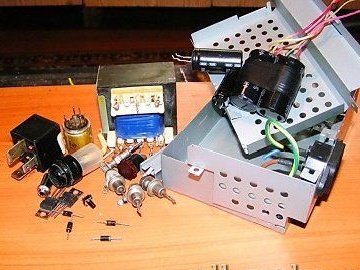
Electronic filling.
Some boards were bought by the author, and some were made by the author on their own.
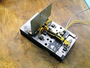
On the radiator there are 7 power supply stabilizer microcircuits. with a total capacity of 7 A. The amplifier consumes about 5 A.
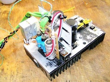
The author made a screen of tin protecting from interference that stabilizers create.
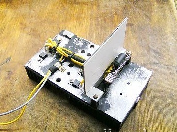
Mounting the amplifier on a TDA 7265 chip with a relay switching AC, since the relay contact is more reliable than a switch.
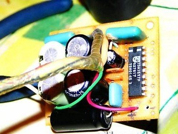
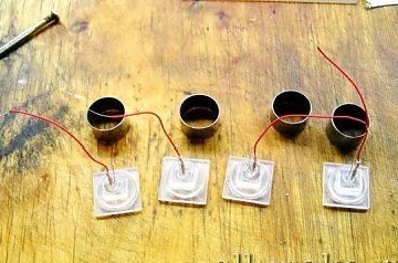
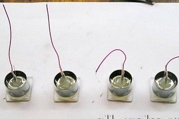
Mounting an amplifier for headphones with a power of 2x5 W, the signal from the amplifier goes directly to the emitters.
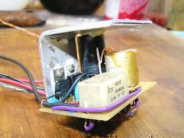
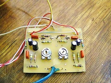
The indicator is controlled by a transistor circuit from an old tape recorder.
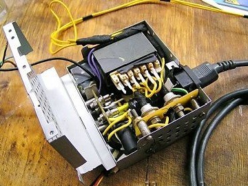
Installing relays, stabilizers and a radiator on a power wiring board.
Installing an amplifier power supply.
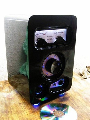
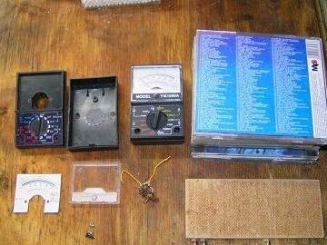
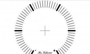
The indicator is made of milliammeters from Chinese testers, the ammeter arrows are painted black.
The creation of the body.
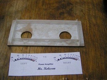
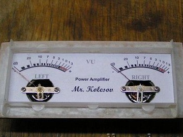
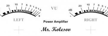
The scale is drawn by the author himself.
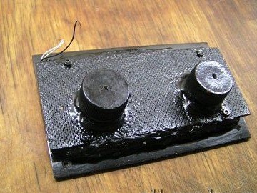
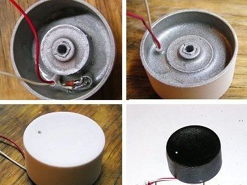
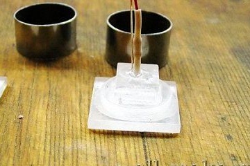
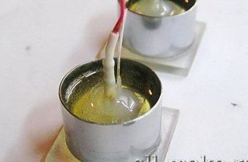
Installation of protective caps for the mechanical parts of the indicator. They are made from bottlenecks.
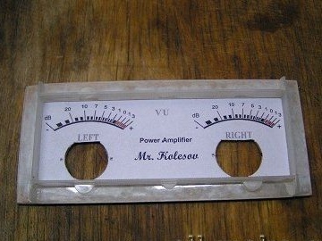
Trying on indicators.
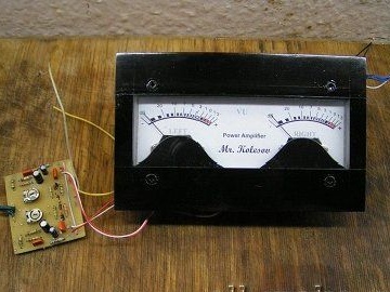
A voltage amplifier was made for a cleaner sound path.
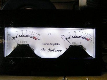
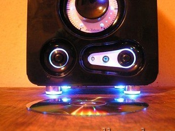
Work on the backlight.
Scale.
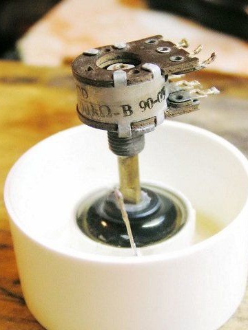
The volume control is made on a variable resistor.
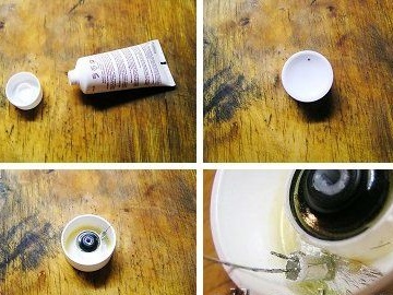
Installation of control knobs.
used a tube cap with cream, a tape recorder handle.
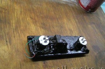
Silver staining and epoxy coating. So that the paint does not peel off, the author processed everything with a fine sandpaper.
The scale is sandwiched between sheets of plexiglass installed in place.

Installation of LEDs and painting.
Creating a contact panel.
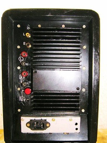
Network button installed. The speaker switch is made with a constant signal direction to the headphones, regardless of speakers.
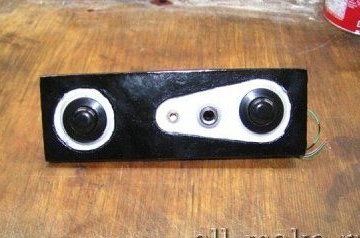
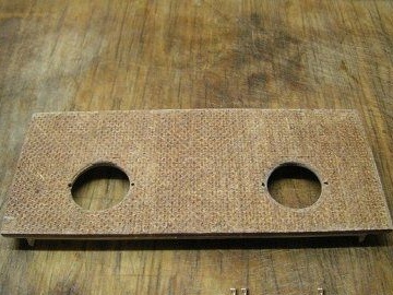
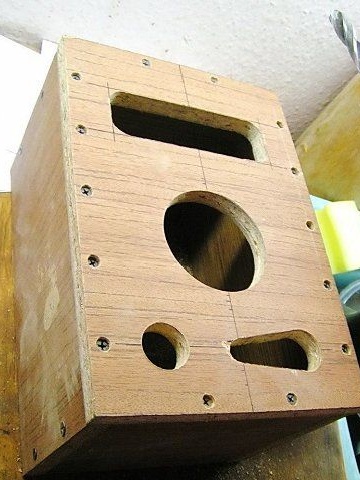
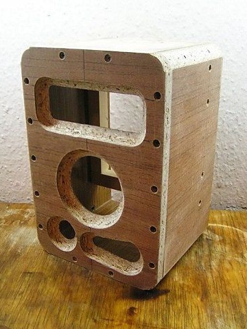
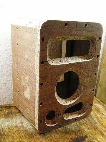
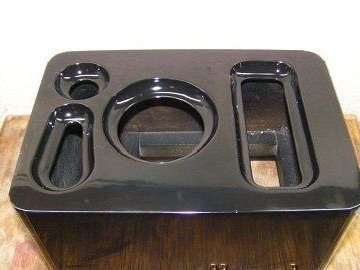
The holes were created with crowns on wood, and the crown of a slightly larger diameter made the edging of the hole.
Then the author installed the connectors for headphones of different diameters 3.5 mm and 6.3 mm, in order to avoid fuss with adapters.
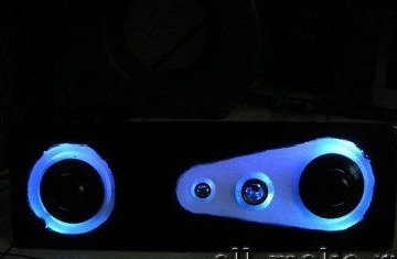
Silver was dyed so that the light was scattered evenly, and then with paint so as not to highlight everything next to the panel.
LEDs are installed.
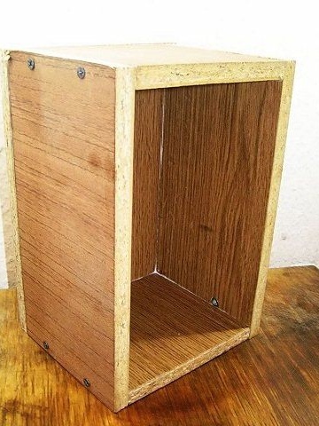
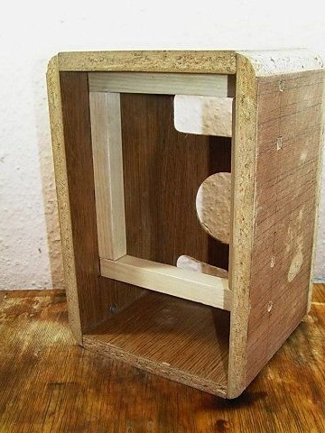
Housing

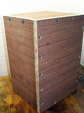
Creating a housing for the amplifier required a lot of time and diligence, but since the aesthetic appearance of his product was important to the author, he did not spare the time and performed everything as efficiently as possible.
A chipboard plate was used, which the author sawed into the necessary parts and then assembled a body from these parts. It was assembled for self-tapping screws, and the joints were coated with glue for greater strength.
Creating holes for installing control knobs, indicators, and more. After that, the edges of the hole were machined with a manual milling cutter.
The back wall is fixed to the bars. In order not to leave the cooling radiator in sight, a sufficiently large indent was made from the edge. This allowed not only the radiator to be hidden, but also all other parts with wires. Thus, nothing prevents installing the amplifier close to the wall.
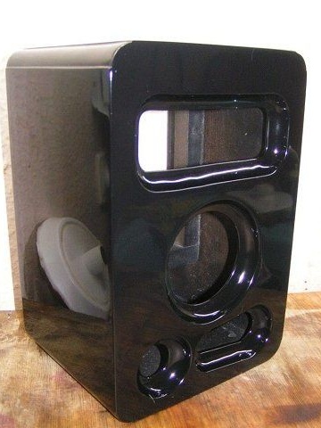
Then the author proceeded to the stage of paint work and putty. Polymer putty with the addition of glue pva excellent lay on the primer. Then the author started painting in several layers with varnishing and subsequent polishing.
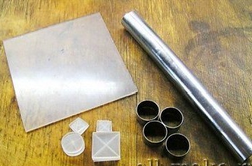
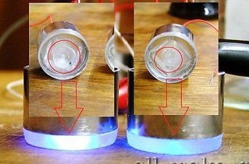
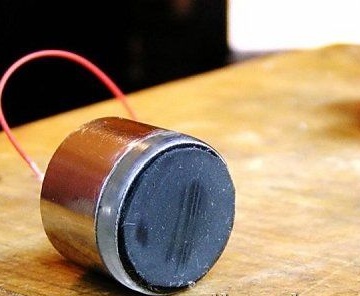
Creating supports from a chrome pipe 25 mm and Plexiglas 3 mm.
Finalization of workpieces and installation of LEDs.
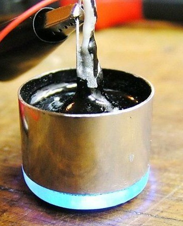
Bonding parts.
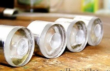
The semiconductor is fixed to hot melt adhesive.
After drying the parts, the author removed the excess plexiglass and polished the edges.
Create a scattering lens.
View without a lens.
Refinement of details.
Gaskets were made from the bicycle chamber, on which foil was glued to reflect light.
As a result, we got such a sound amplifier.