» Electronics » LEDs »LED flasher with two transistors

LED flasher with two transistors

Today I will tell you how to make a simple flasher on two transistors. This homemade will help beginner hams in the development of radio electronics. Materials for creating emergency lights can be found in any electronic store.

To create an emergency light we need:
2 LEDs (any color at 3 V)
2 resistors (at 330 OM) and 2 resistors at (at 22 KOM)
2 capacitors (at 16 V and 20 MKF)
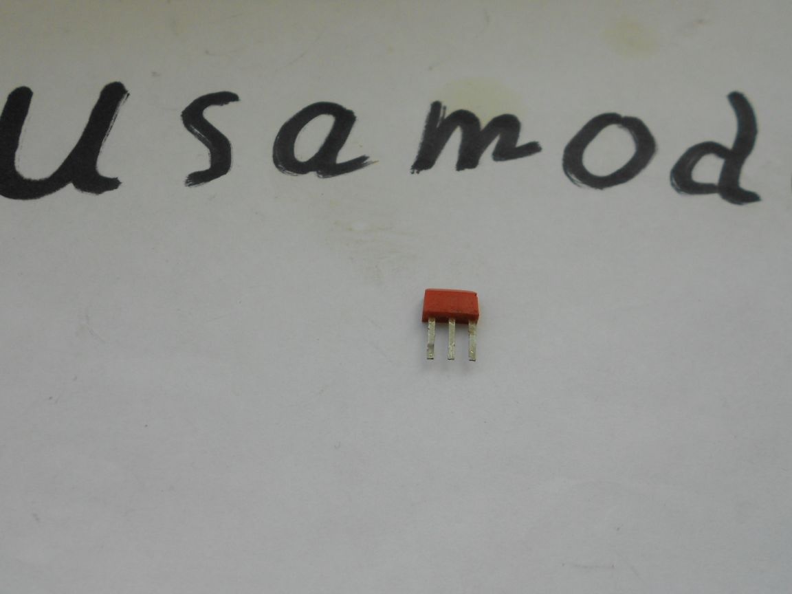
And 2 transistors (KT315)
Well, a 5V power supply

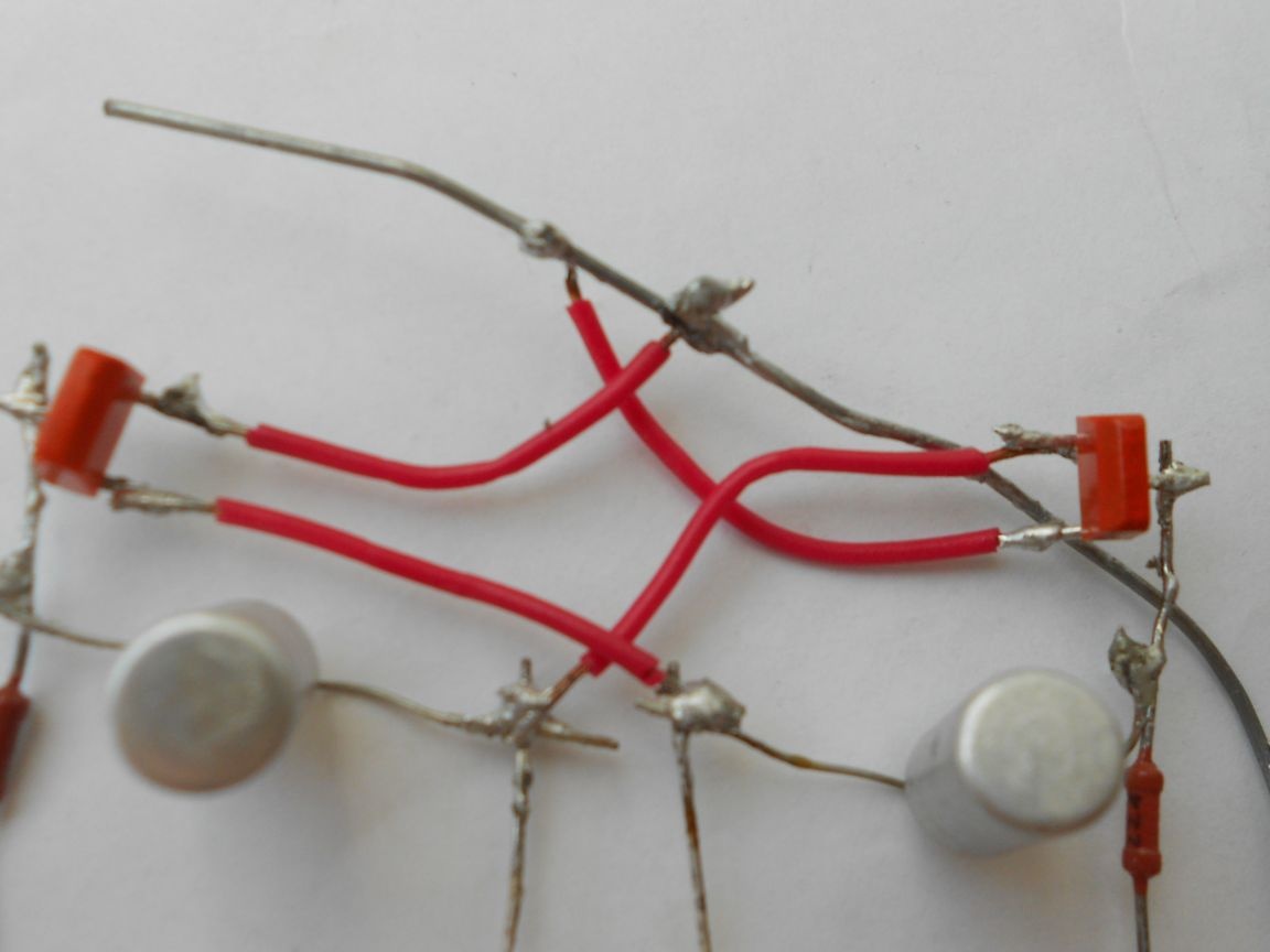
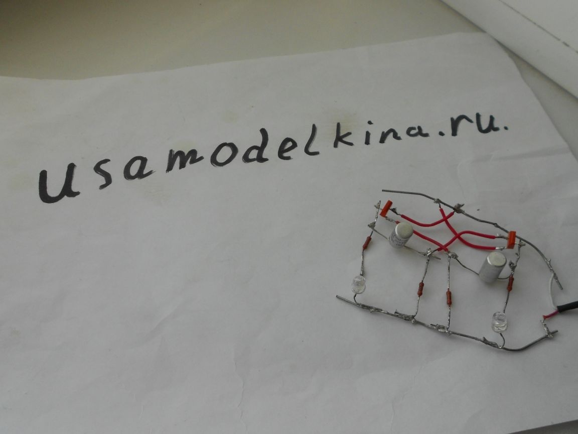
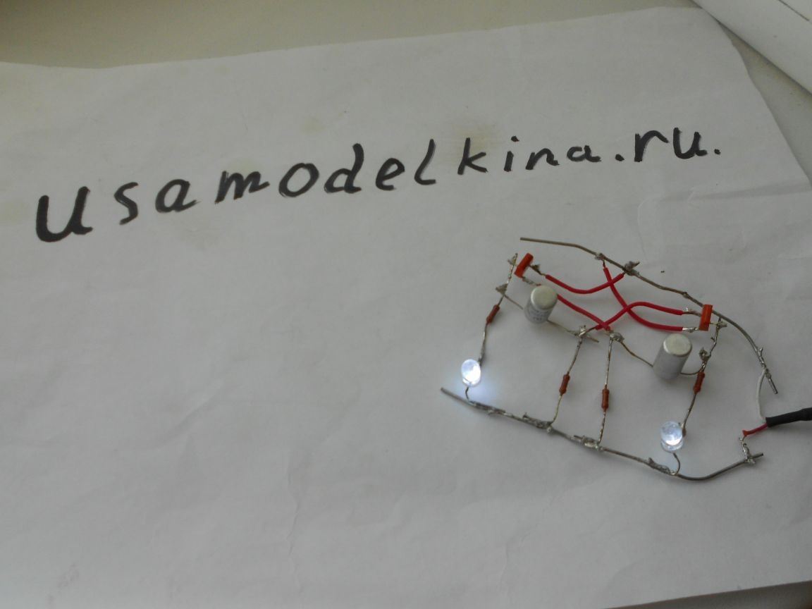
We will collect here according to this scheme:
LED flasher with two transistors

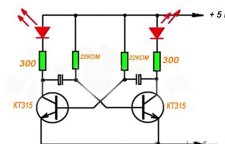
To begin with, we need to solder the pluses of the LEDs to the + power supply, and the minuses to the resistor (by 330 OHM). Next, solder the resistors (to 22 KOM) to the + power supply unit so that one “leg” is on the + power supply unit, and the second on the minus of the capacitor. Next, we must solder the + capacitor to the resistor (at 330 ОМ) .Then we must solder the transistors (be careful, the transistors quickly overheat). The emitter to the - power supply, the collector to the + capacitor and resistor connections to 330 OM, and the Base to the connections - the capacitor and resistor at 22 KOM. (in the picture BKE)
Well, that's all it remains to do is connect the power supply to the network and enjoy the flashing LEDs. The flashing frequency can be adjusted by changing the resistance of the resistors.

1
4
1

Add a comment

    • smilesmilesxaxaokdontknowyahoonea
      bossscratchfoolyesyes-yesaggressivesecret
      sorrydancedance2dance3pardonhelpdrinks
      stopfriendsgoodgoodgoodwhistleswoontongue
      smokeclappingcraydeclarederisivedon-t_mentiondownload
      heatirefullaugh1mdameetingmoskingnegative
      not_ipopcornpunishreadscarescaressearch
      tauntthank_youthisto_clueumnikacuteagree
      badbeeeblack_eyeblum3blushboastboredom
      censoredpleasantrysecret2threatenvictoryyusun_bespectacled
      shokrespektlolprevedwelcomekrutoyya_za
      ya_dobryihelperne_huliganne_othodifludbanclose
7 comments
Guest Alexander
I saw this circuit in a very old book "young radio amateur" ..... I even collected it, the first circuit was probably mine.
Why is it needed? Bauble. This is not good for a car. There is it all in the "Internet", just for the car.
And the switching frequency (of this cartoon) depends not only on the values ​​of the resistors, but also on the capacitance of the capacitors.
the right thing
2 LEDs (any color at 3 V)
2 resistors (at 330 OM) and 2 resistors at (at 22 KOM)
2 capacitors (at 16 V and 20 MKF)

Not OM, but Ohm, not COM, but ohms, not MKF, but microfarads. “any color at 3 V” - this does not happen: each color has its own boundaries of a typical voltage drop.
In principle, the circuit will work without problems, because it is a classic multivibrator. LEDs can, indeed, be set to any, only have to, perhaps, pick up collector resistors.
Well, can instead of diodes put power transistors to supply power to the bulbs?
Author
Yes, the LEDs are ordinary (the main thing is 3 Volts). They blink due to the transistors opening alternately. The blinking frequency can be changed by changing the resistance of the resistors (by 22 KOM). For convenience, you can solder a variable resistor.

As for the turns relay on the car ... In this area, I am not strong and I can not help with anything: pensive:
Please do not kick, because I do not understand much about electronics. How will they blink? Capacitors? Are the LEDs ordinary? Or flashing LEDs?

According to this principle, I want to make a turn relay on a car, since thermal relays have already bored me.

We advise you to read:

Hand it for the smartphone ...