So, you see the circuit diagram of the low voltage warning device for a car lead-acid battery. It is very important to monitor the battery charge in order to prevent excessive battery discharge, which can lead to negative consequences for your rechargeable battery, we will make a simple device that monitors the voltage level on the battery terminals.

Having collected a simple and very useful scheme of a sound discharge detector, you can quickly find out about low voltage at the battery terminals and take measures: charge it with an ordinary mains charger or through the built-in generator in transport.
The scheme consists of two parts:
the first, monitoring the potential difference andthe second is the most elementary sound generator. Let's analyze the principle of work.
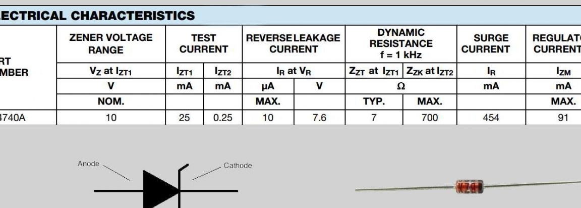
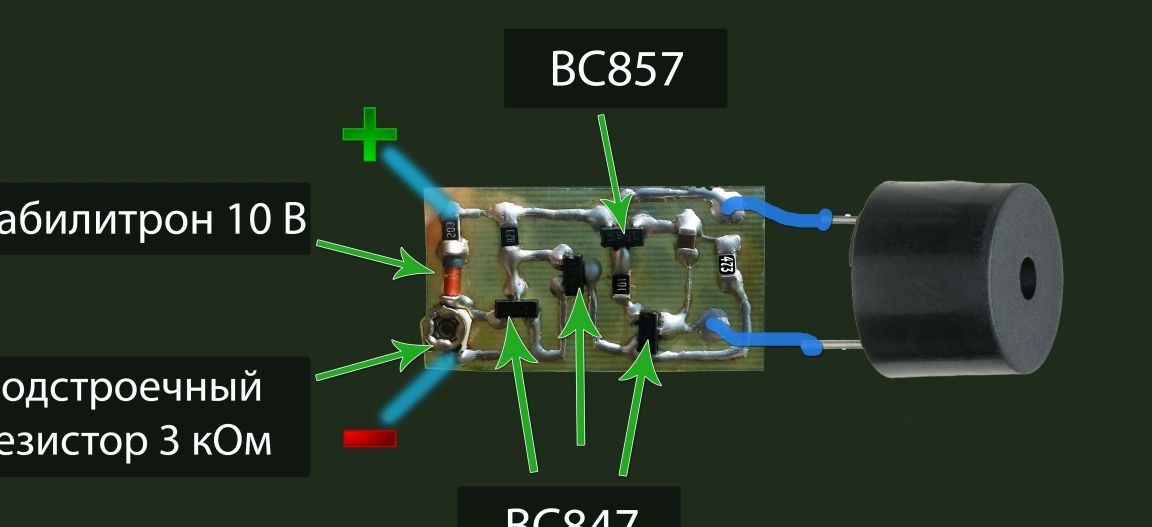
First, a zener diode resistor and another resistor are connected in series. At the zener diode, the voltage for which it is designed, drops to 10 V, in its technical documentation (1N4740A) the maximum power is 1 Watt, the stabilization voltage is 10 V (ZENER VOLTAGE RANGE), which means the maximum allowable current is 1W / 10V = 0.1A , but actually 91 mA (REGULATOR CURRENT), the nominal stabilization current is 25mA (TEST CURRENT).
We calculate the resistance of two resistors. As you know, when connected in series, the current flows on all elements of the circuit the same, but the voltage drop across the different components varies. According to the condition, about 10 V should fall completely on the zener diode, the maximum voltage at the battery terminals is 14 V, so 14-10 = 4 V should remain in total on two resistors R = 4V / 25mA = 160 Ohm. But in fact, such a large idle consumption is unacceptable to us, so we take resistors with a much larger resistance, as a result of which the current decreases and at the zener diode it drops less than 10 V. I chose a constant and variable 3 kOhm at 20 kOhm. The current consumption will be only about 200 μA.
To open the transistor VT1, you need to apply plus to its base, and minus to the emitter, the voltage is about 0.7 V (depending on your instance), we have the lower resistor R2 for this, we use a subscript resistor for fine tuning.
The base of VT2 is connected to the collector of transistor VT1. Thus, when the voltage is higher than normal (on the battery), VT1 is open and the VT2 base is connected in the red - it is closed.When the voltage on the battery becomes less than the norm (you choose the norm yourself), the first transistor closes and now nothing prevents the second from being open through a 10 kOhm resistor.

Analysis of the generator of sound vibrations: it consists of two transistors of different conductivity. Suppose that at the initial time, all transistors (VT3 and VT4) are closed due to the fact that a plus is fed to the PNP transistor through the speaker and capacitor. As soon as the capacitor is fully charged, it will no longer conduct current to further close VT3 and now nothing prevents it from opening through the resistor R4. When VT3 opens through its EC, it will “flow plus” to the NPN base of VT4 and it will also open - now the current flows through the FE of the fourth transistor and the speaker (clicks). During this click, the capacitor is closed through the resistor and the open transition of the VT4 CE, naturally it is discharged, and this takes a certain time, which depends on the capacitance of the capacitor itself and the resistance value of the resistor. As soon as the capacitor is discharged, VT3 closes again through the coil of the dynamic head and C1 and then everything goes on by itself. Despite the simplicity of the RC sound generator in practice, it does not always work stably.
The 100 ohm resistor R5 here limits the base current of the NPN transistor.
Schema setup
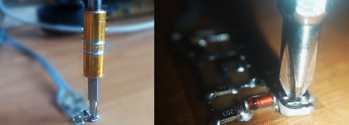
We have to do this: connect a regulated power source to the circuit, having previously set the voltage to 12 Volts (which corresponds to a discharge of 75% without connected load (you can choose another value, the table below) and changing the resistance of the RV1 interline resistor, we achieve that, with a small the turn of the resistor bolt began to beep the speaker, this is the whole setting.
That is, we set such a voltage between the base and emitter VT1, when the transistor is closed with an unacceptable discharge (my transistor has a saturation voltage of 658 mV) and with the slightest increase in voltage on the battery, the voltage drop in R2 inevitably increases and, therefore, more than U BE - it opens, closing VT2.

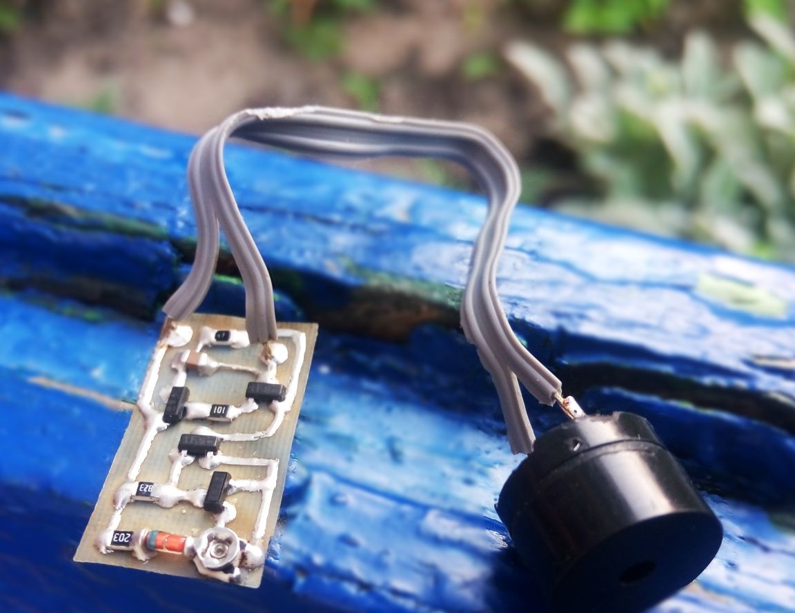
The circuit is very simple and I assembled it using components for surface mounting, which contributed to the maximum miniaturization of the scarf, dimensions 24 by 13 mm. Consumption in stand-alone mode reached ~ 2 mA, and when the signal reaches 15-20 mA.
Download board:

The case is a plastic box, such a box in which I made a hole for the buzzer.
If you are assembling a circuit with discrete elements, I recommend taking a potentiometer of the type 3296W for this device, since it has a very accurate and smooth adjustment of resistance, but I used a miniature smd resistor. Use a small electromagnetic speaker, similar to a black barrel (electromagnetic sound emitter), as a transducer of electrical vibrations to sound.