
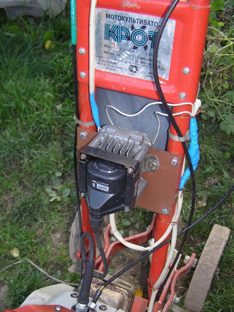
Now you can buy any equipment in stores for land works, but many on the farms use walk-behind tractors and tiller cultivators.
Other owners use Krot motoblocks for 20 years and suddenly a breakdown - refused electronic ignition unit MB-1.
The main disadvantage of the MB-1 electronic unit is its miniaturization and circuit flaw,
Although there is a proven option with light motorcycles and mopeds - a generator coil, electronic filling and an ignition coil - there are separate components and there are no problems in the ignition system.
And in MB-1, the winding of the generator coil was made with very thin wiring and the ignition coil is small, and most importantly, the electronic part of the circuit is located on the engine crankcase and heats up to 80 degrees. And the KU202N thyristor used in the circuit is designed for 75 degrees. Therefore, constant malfunctions. The same thyristors were used in ignition schemes operated on light motorcycles and mopeds and worked reliably. The thin winding wire of the generator coil does not produce more current and set the storage capacitor to 1 uF.
Try to smash these ignition elements. I will give an example of how the ignition unit was improved by a friend in the forum.
- The ignition coil is automotive, with multiple reserves and a spark twice as powerful as before.
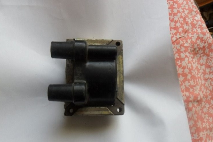
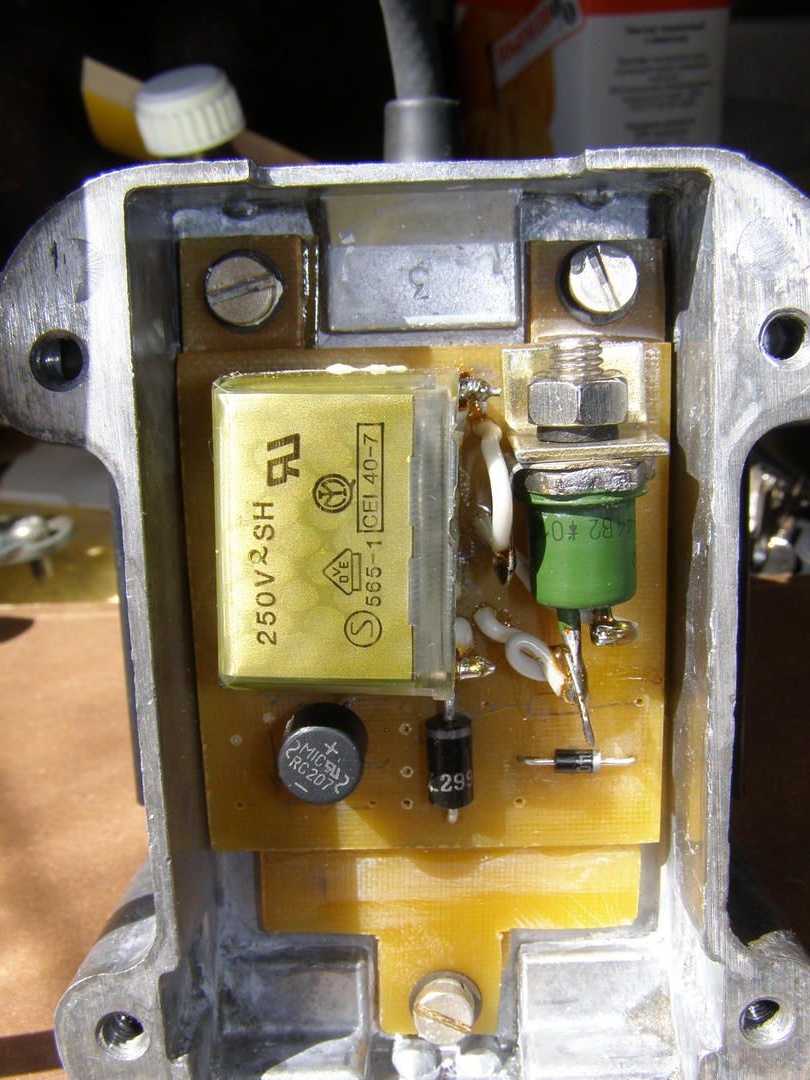
A car ignition coil was found. An electronic circuit is mounted in the housing of the burned switch.
I mounted the ignition coil on the steering wheel plate of the walk-behind tractor.
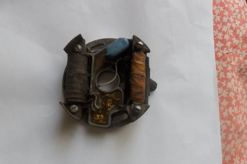
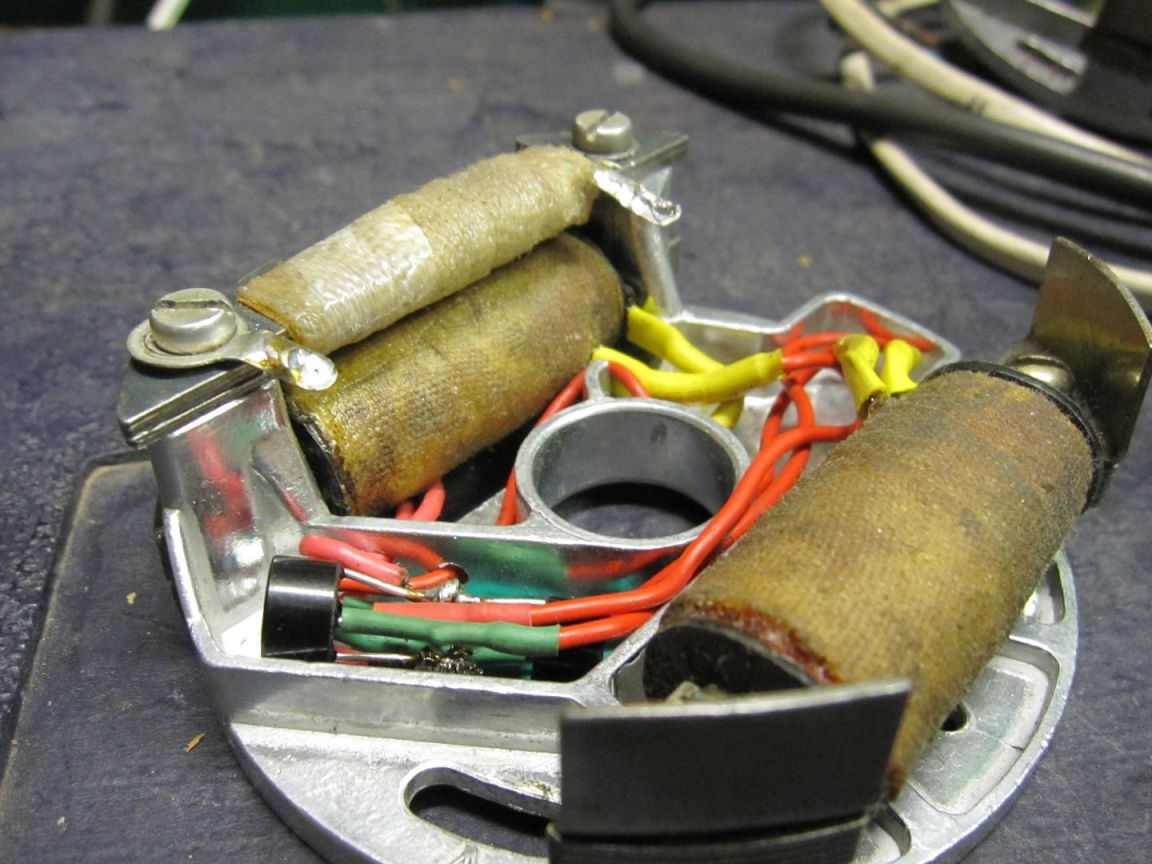
The generator coil and the sensor coil were left from the MB-1 unit
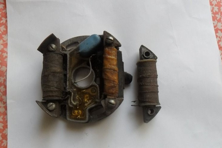
you just need to fit the seat under it.
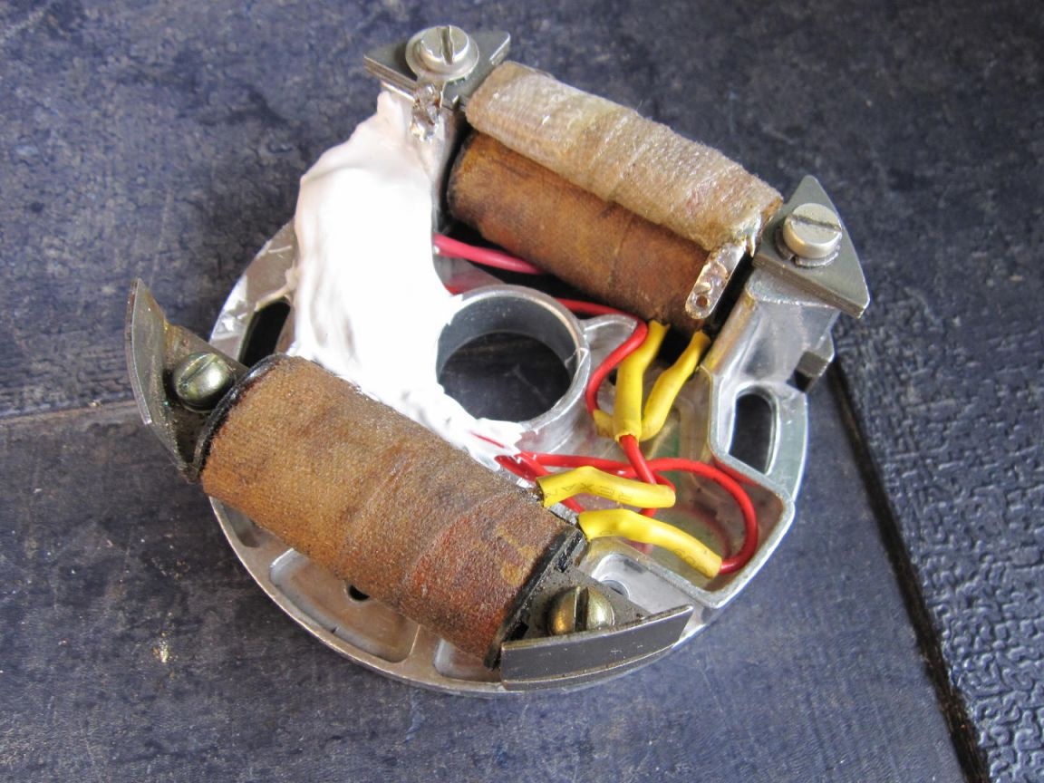
A flywheel with four magnets is installed on the walk-behind tractor, one of them is turned upside down so as not to be wiser with phrases of windings - each generator coil with its own diode bridge.
After all the alterations - multiple ignition reliability. Thyristor T 122-25-8 military model, a thousand-volt diode bridge, eternal ignition coil.
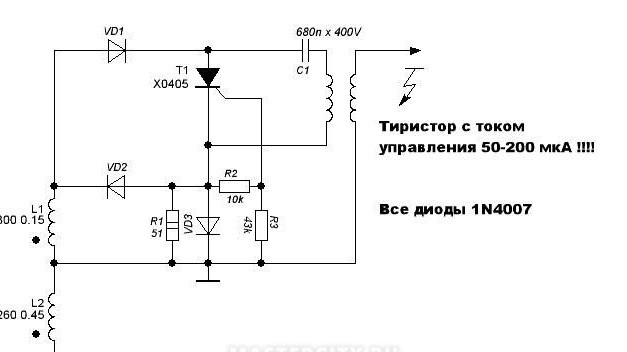
Ignition circuitry:
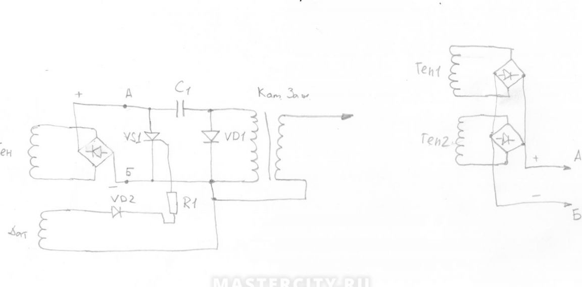
The figure on the right is the connection of generator coils. Connect at points A B in the left circuit.
Diode bridge - RC207.
Capacitor C 1 - 1 uF.
Thyristor - at 10 amperes and at 800 volts. I set - T 122-25-8. 25 A 800 V.
Diode VD1 - type HER308, quick action.
Diode VD2-1N4007.
Resistor R1- within 2 kOhm.
The best part is that having a walk-behind tractor is a pleasure.