
The original idea to make a flashlight on Peltier elements was proposed by the author homemade. As you know, Peltier elements are a thermoelectric converter. When voltage is applied, one side of the cell heats up and the other cools. Conversely, when an element is heated, it generates energy. When it comes into contact with human skin, only 0.1 V. is produced. This complicates the task, since the blue LED used by the author needs a voltage of 3.5 V. But here, the author found a way out. So let's get started.
Tools and materials:
Peltier elements;
-Copper wire;
-Blue LED;
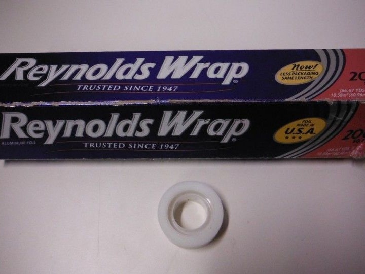
-Toroid;
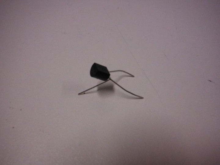
-Bipolar transistor;
Resistor 4.7 Ohm;
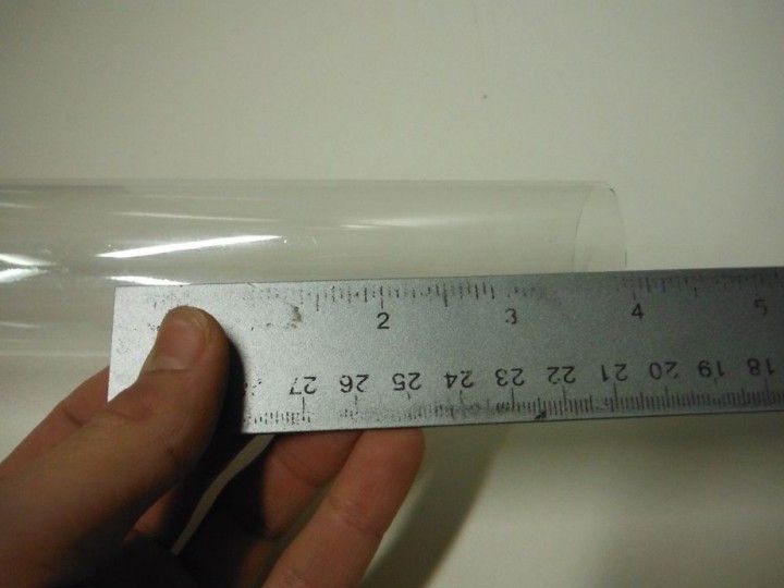
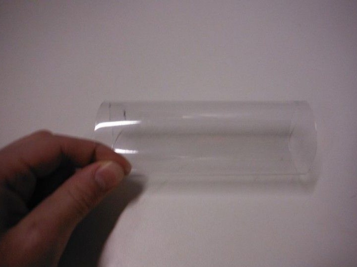
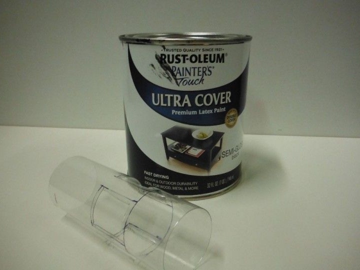
-Plastic tube;
-Paint;
-Cardboard;
-Foil;
-Scotch;
-Scissors;
-Soldering iron;
-Rule;
-Glue gun;

Step 1: Making the Case
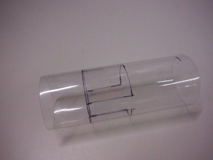
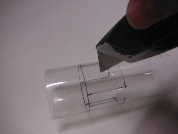
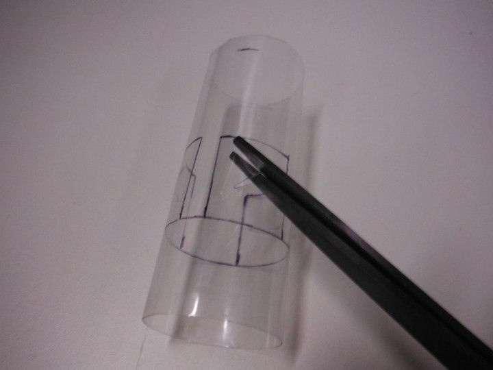
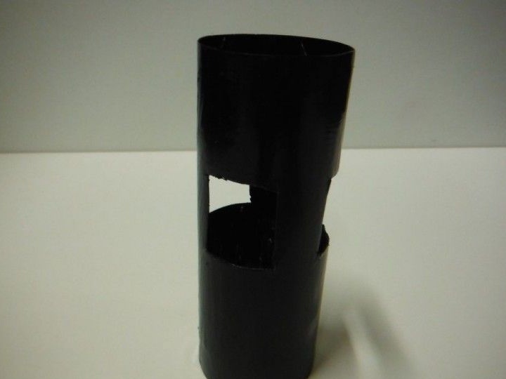
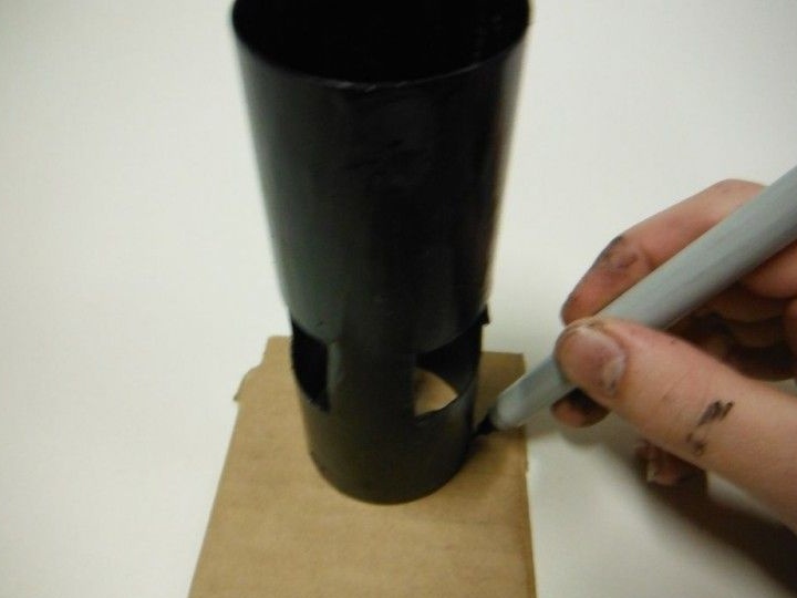
First, the author cuts 10 cm of the tube. In a circle, closer to one edge, makes markings for Peltier elements. There will be three of them in total. Cuts windows.
Stains the tube with black paint.
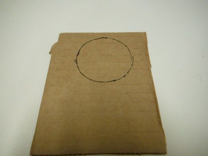
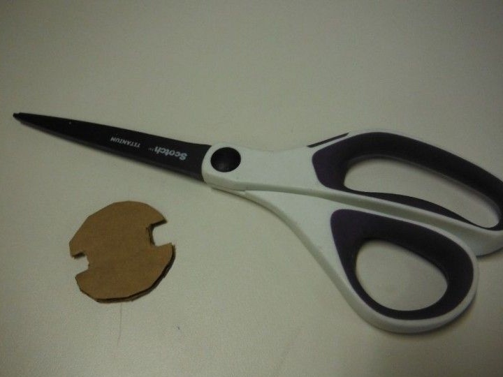
A circle with a diameter equal to the diameter of the tube is cut out of cardboard.
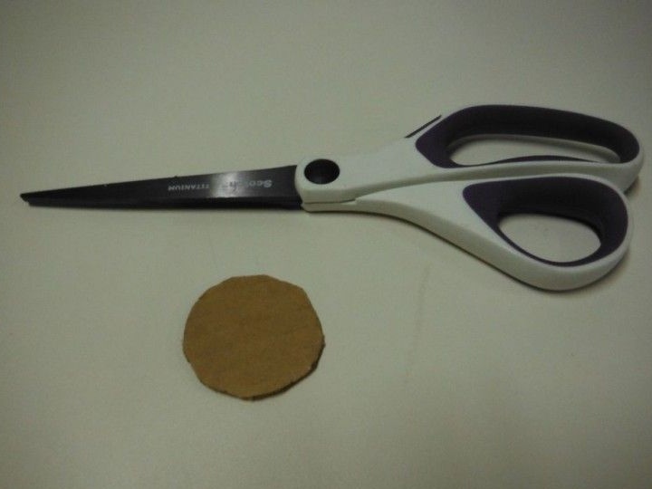
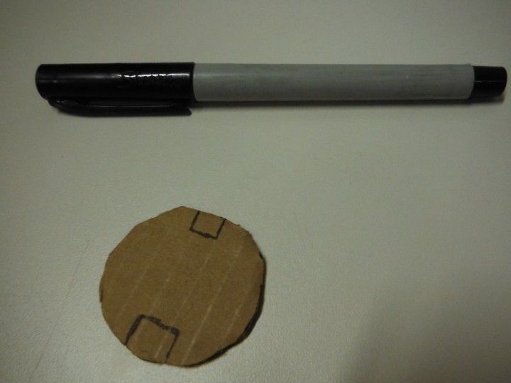
Cuts cardboard on two sides opposite each other. Glues to the end of the pipe, which is closer to the slots.
Step 2: Installing Elements in the Case
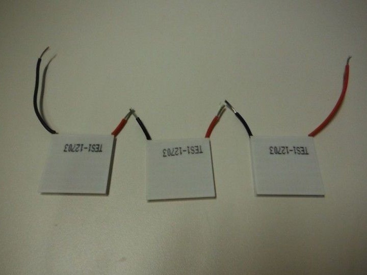
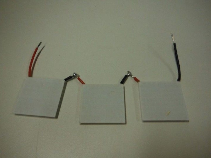
Consistently connects Peltier elements. The middle ends are shortened and soldered. Solder wires to the extreme ends.
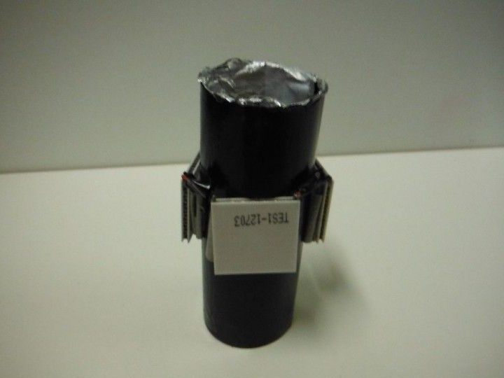
Mounts the elements on the case, installing them in cut windows.
He pulls the ends of the wires through a hole in the cardboard into the case.
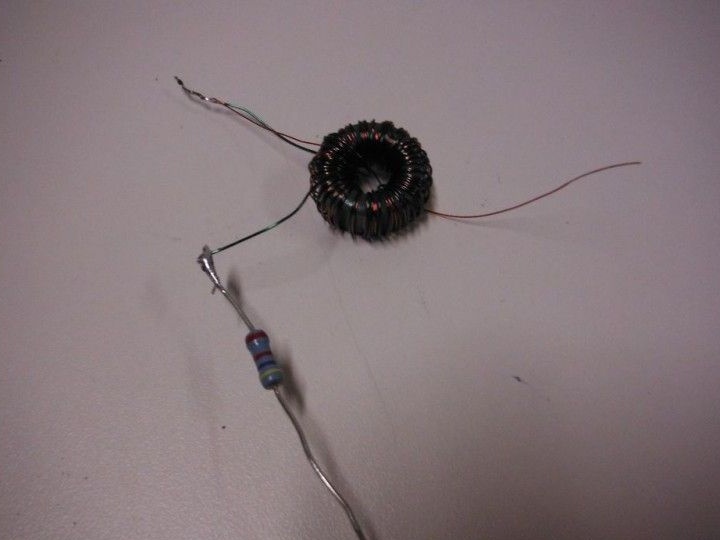
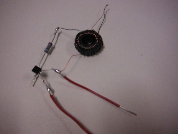
Step 3: Toroid
Since the LED operates on a voltage of 3.5 V, and the elements can only give out 0.3, the author collects the so-called "joule thief". To do this, he needs a toroid.
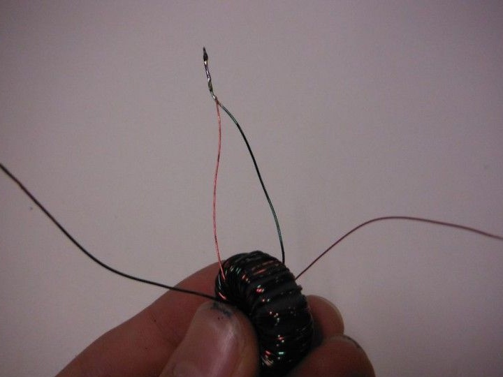
In order to make it easier to distinguish the wires, the author took them in different colors. Weaves wires between each other. Then, passing the end through the ring of the ferrite core, wraps them on the core. Winding until it completely covers the core. Cleans the ends. He takes two ends of a different color, from different sides of the ring and twists them. Then solders. This is a common point.

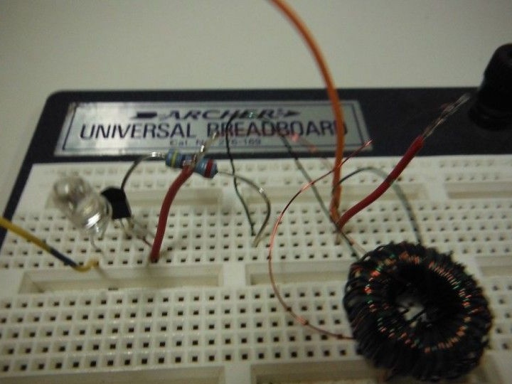
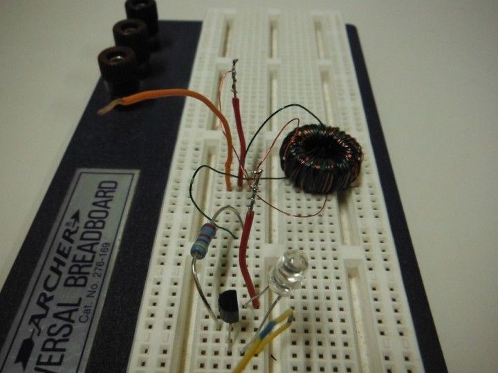
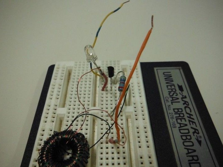
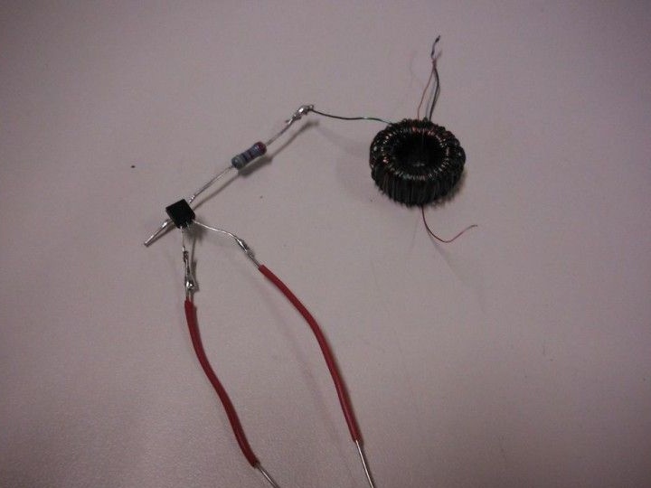
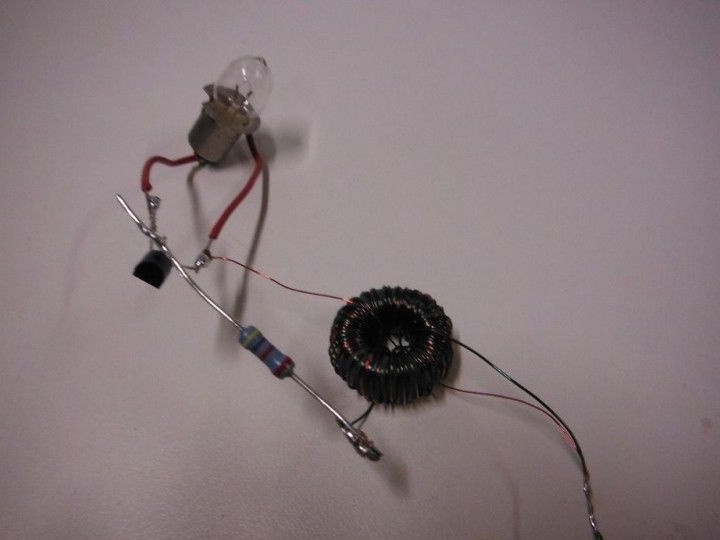
Step 4: Verify Circuit Health
Checks the operation of the circuit by connecting the circuit as indicated in the photo. The circuit is as follows: the end of the toroid-resistor-resistor is the middle leg of the transistor; the second end of the toroid is the right leg of the transistor + LED cathode + negative battery contact; the anode of the LED is the left leg of the transistor; minus the batteries are the soldered ends of the toroid.
The battery uses a 1.5 V battery. The author used NPN transistor of any marking. If everything is assembled correctly, then the LED should light up.
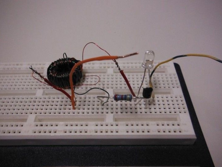
Step 5: final assembly of the flashlight
It solders the circuit with some changes. A resistor is soldered to one end of the toroid. Jumpers are soldered to the side legs of the transistor, and the free end of the resistor to the middle legs. The second end of the toroid is soldered to the right terminal of the transistor and to it the same cathode of the LED. The anode is soldered to the left leg.
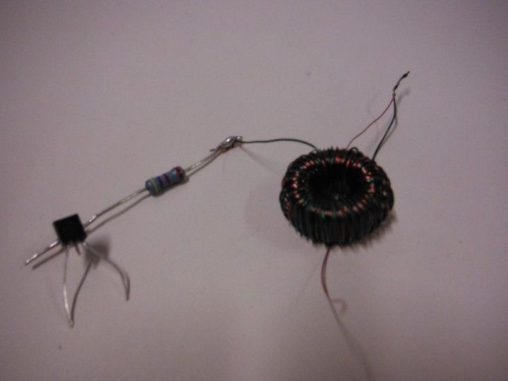
The minus of the Peltier element is soldered to the right foot of the transistor. Plus solders to two toroid wires soldered together.
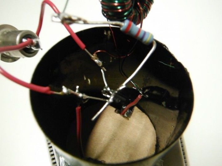
Insulates Peltier elements with aluminum foil.
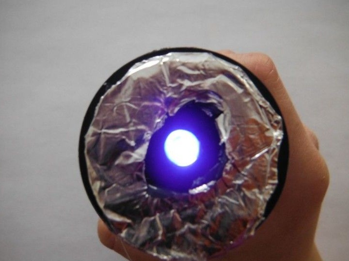
Installs a cover with a hole for the LED. Fixes the LED with hot glue. A reflector cut out of foil is installed on top of the lid.
The lantern is ready.
In the future, the author plans to improve the flashlight by installing batteries and a USB output. This will allow you to charge your gadgets.