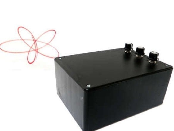
The history of the invention of the spirograph is quite entertaining. In 1962, an English engineer developed fuses for aerial bombs. In order to quickly and accurately draw curves, he tried to make a special tool. As a result, as is often the case with inventions, the spirograph did not fit for drawing, but it turned out to be a wonderful children's toy. With the development of technology, the principle embodied in the spirograph began to be used in a device for laser shows. It was such a device that the author decided to make homemade.
Tools and materials:
-3 mirrors with a diameter of 2.5 cm;
-Box for the case;
-4 plastic jars;
-3 electric motors 1,5-3 V;
-3 potentiometers with a nominal value of 25 ohms and 3 watts with handles;
-Laser pointer;
-Switch;
-2 battery compartments for AA and AAA;
-Fasteners;
-A screwdriver;
-Glue gun;
-Wire;
-Soldering iron;
-Hacksaw;
-Nippers;
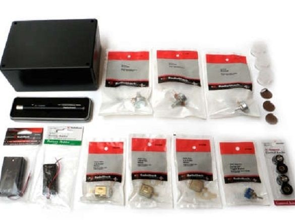
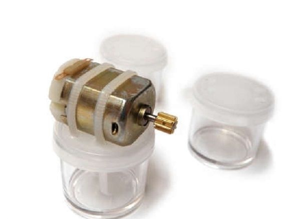
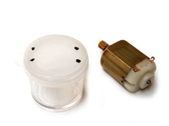
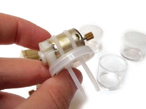
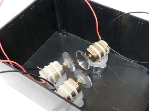
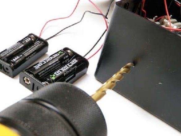
First, the author installs gear motors on plastic jars. Marks places for fastening on the cover. Using a drill makes four holes. Installs the electric motor and fixes with plastic clamps. In this case, it is necessary to pay attention so that the moving parts of the electric motor do not touch the can cover.
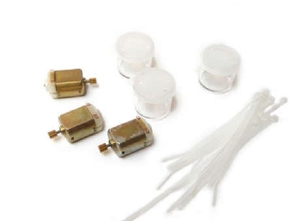
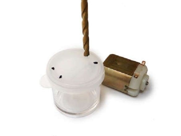
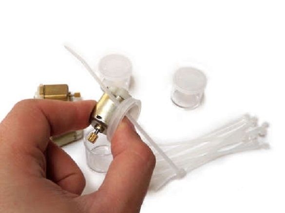
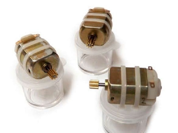
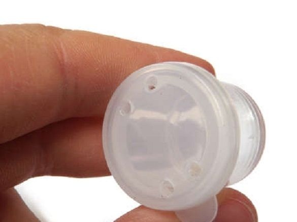
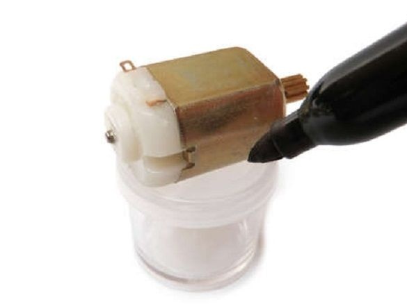
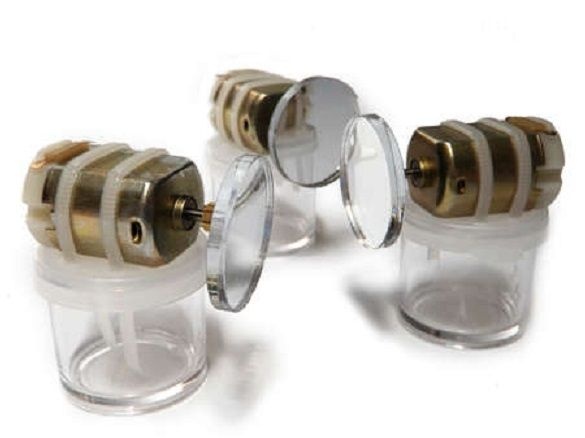
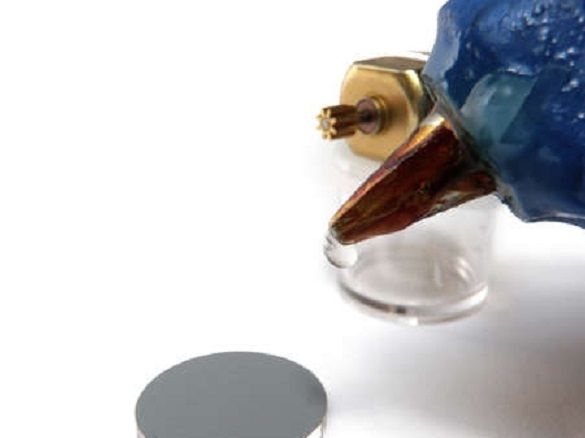
Using hot-melt adhesive, it fixes on the gear of the mirror. If the mirrors are slightly shifted from the center, this will give an interesting picture in the future.
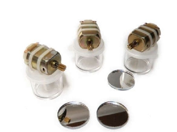
Solders to the conclusions of the electric motor wires. The red wire is for positive, and the black wire is for negative.
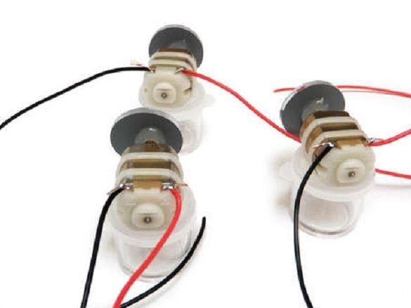
Installs electric motors in the case. Two next to each other, the third opposite them in the middle. And they are all rotated at an angle to the body. Mounted with a glue gun.
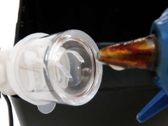
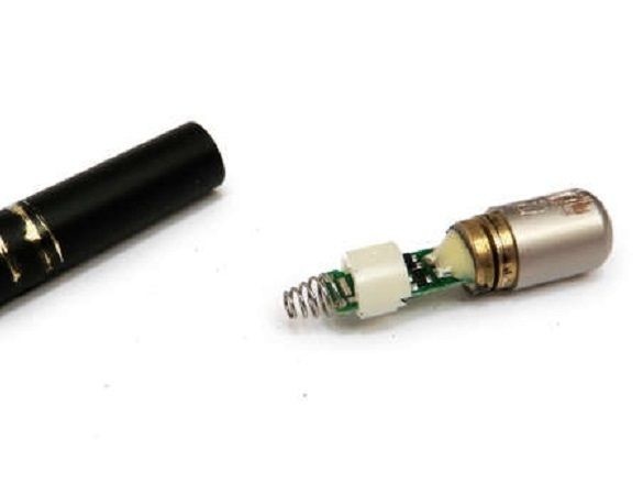
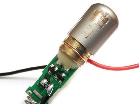
Dismantles a laser with a board from a laser pointer.
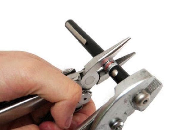
Removes insulation from the red wire. Wraps the laser housing with wire and solders it.
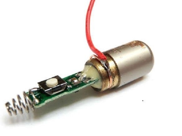
By deploying the laser with a button away from you, a black wire is soldered to the right terminal.
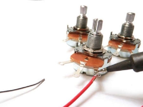
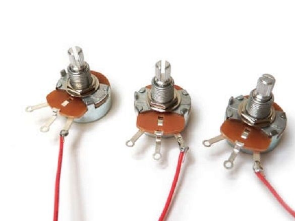
Connects potentiometers. A wire from the positive terminal of the electric motor is soldered to the middle contact of the potentiometers. A piece of red wire is soldered to the right pin.

Tumbler author uses type DPDT. The toggle switch is connected as follows: 1) two positive contacts of the battery compartments (red wires) with the two middle terminals of the toggle switch, 2) the right contacts of the potentiometer (red wires) to the contact of the toggle switch adjacent to the contact of the battery compartment AA, 3) the red wire from the laser is soldered to the contact adjacent to the contact of the AAA battery compartment.
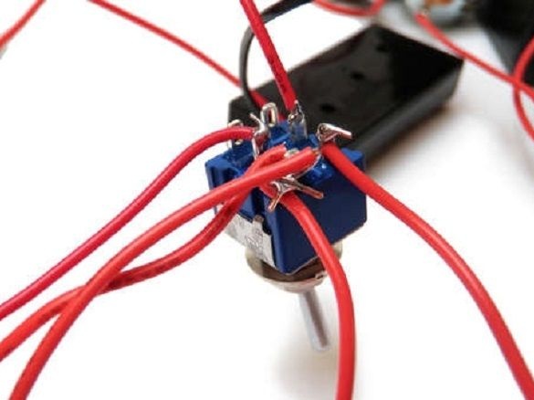
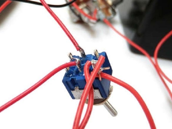
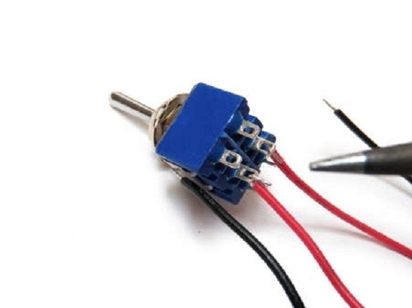
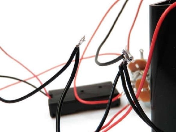
Then solder the negative wire from the AA battery compartment to the black wire of the electric motor. Negative wire from AAA to the black laser wire.Thus, when voltage is applied, the electric motors, through potentiometers, are powered by AA batteries, and the laser from AAA batteries.
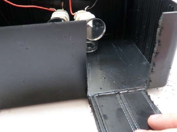
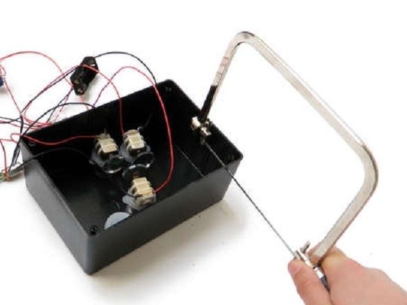
Further, the author cuts a window with a hacksaw in the size of five by five centimeters. The window is located where the laser beam will exit (set experimentally).
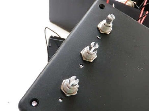
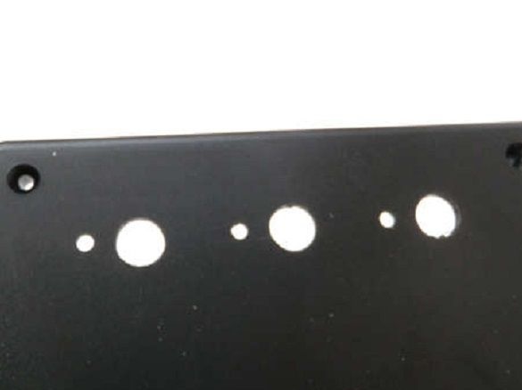
Having drilled holes in the cover, it sets potentiometers and fixes them with a bolt.
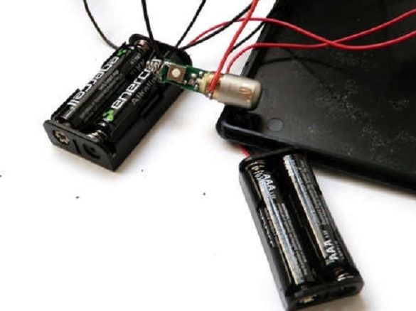
Inserting the battery checks the operation of the assembled circuit.
The toggle switch is located on the side wall of the case opposite the window. Drills a hole for the toggle switch in the wall. Installs it.
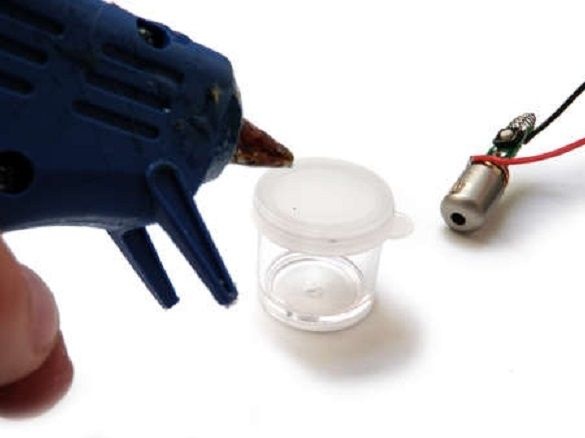
A laser sticks to the remaining jar. Turning on the power of the circuit selects the position of the laser in such a way that the beam reflected from the mirrors gets into the window in the housing. The beam should be reflected from all three mirrors, and only from the last to go out the window. Glues a jar of laser to the body.
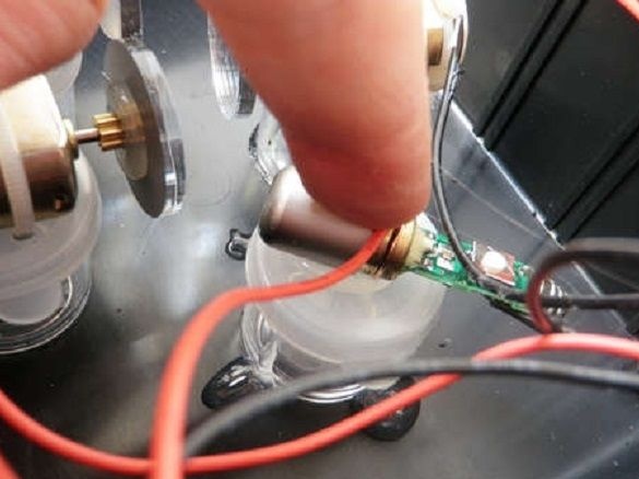
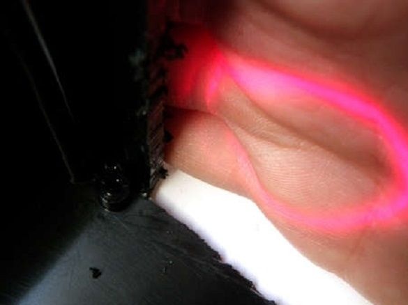
Checks the operation of the device. It is necessary that the beam hits the window without touching the walls of the housing. If the walls touch, you need to expand the window.
Clamps tightens the wiring harnesses.
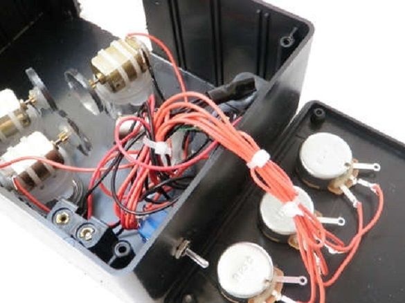
Installs a cover on top.
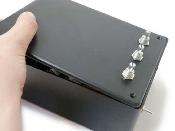
Installs knobs on potentiometers.
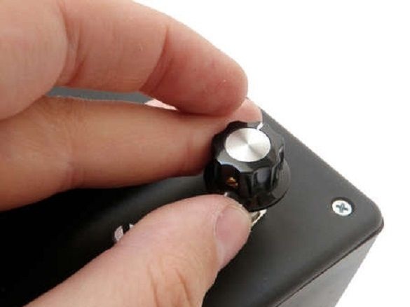
All spirograph is ready. Now you can surprise your friends and neighbors with a laser show.
You can watch the work of a laser spirograph on a video.
