» Electronics »Soldering iron stand with power control

Soldering iron stand with power control


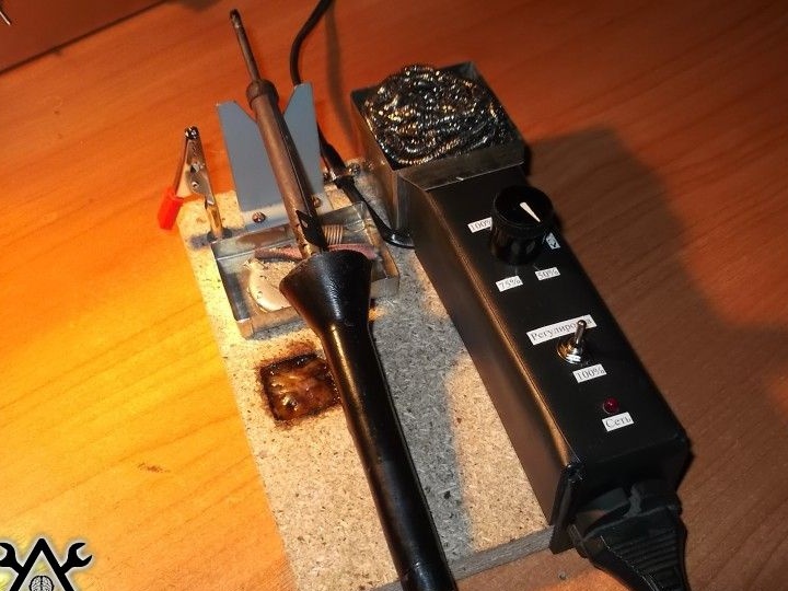
On sites homemade A great many soldering iron stands. The author of the homemade product made this stand based on his previous experience. A distinctive feature of the stand is its built-in power regulator, which allows you to adjust the heating temperature of the soldering iron.

Tools and materials:
-Radio components;
- chipboard;
-Plastic;
-Tin;
-Fasteners;
-Clamp;
-Metal sponge;
-Rubber;
-Glue;
-Drill;
Cutter;
-Soldering iron;
-Hair dryer;

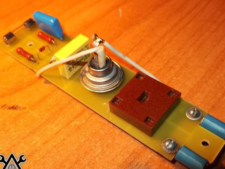
To begin with, the author assembled a power adjustment board according to the scheme.


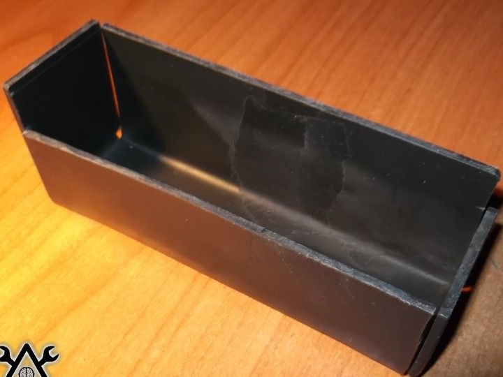
I cut out a blank of the board case from plastic. He bent the plastic using a building hair dryer.

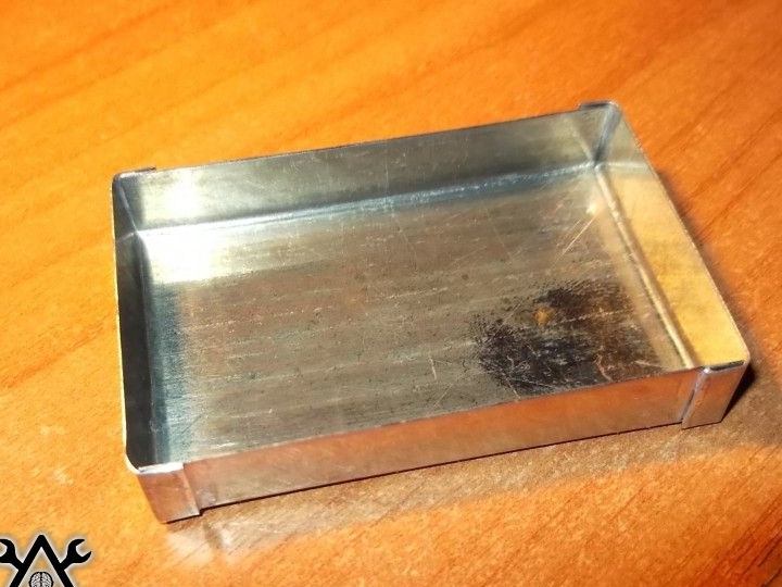
I cut out a box from tin and soldered corners in it.

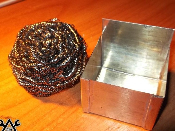
Made another box for a metal brush. Using a brush, the author cleans the soldering iron tip.

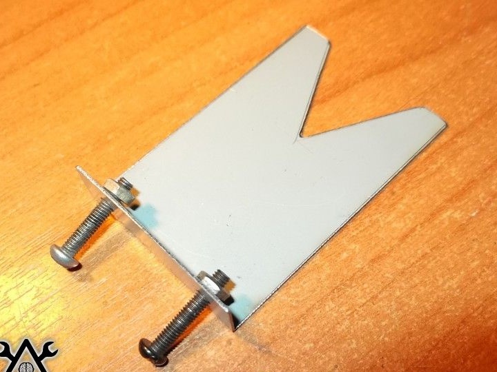
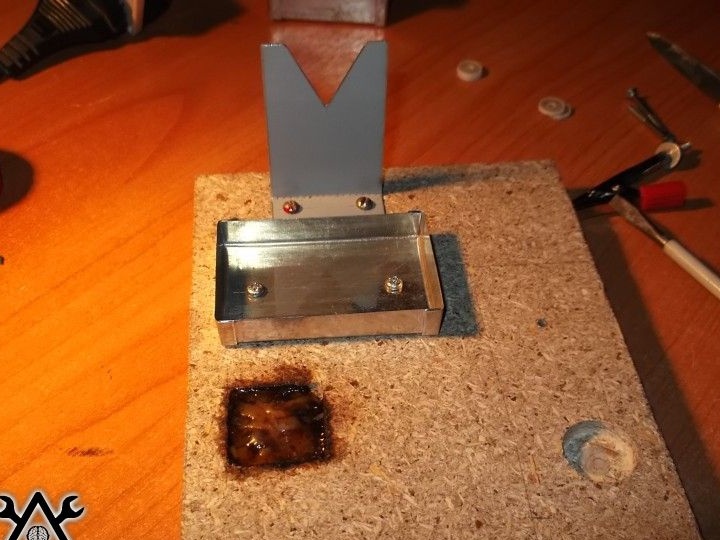
Cut out an emphasis for a soldering iron.

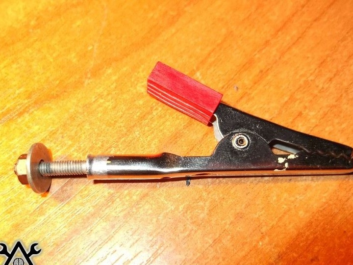
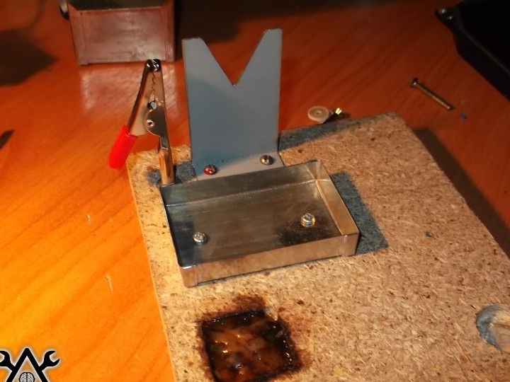
I soldered a bolt to the clamp. He will play the role of a "third hand."

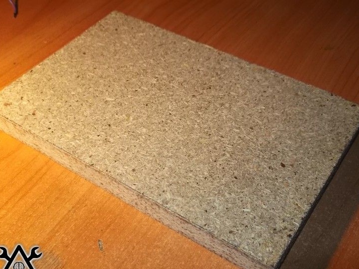
I cut the base out of chipboard.

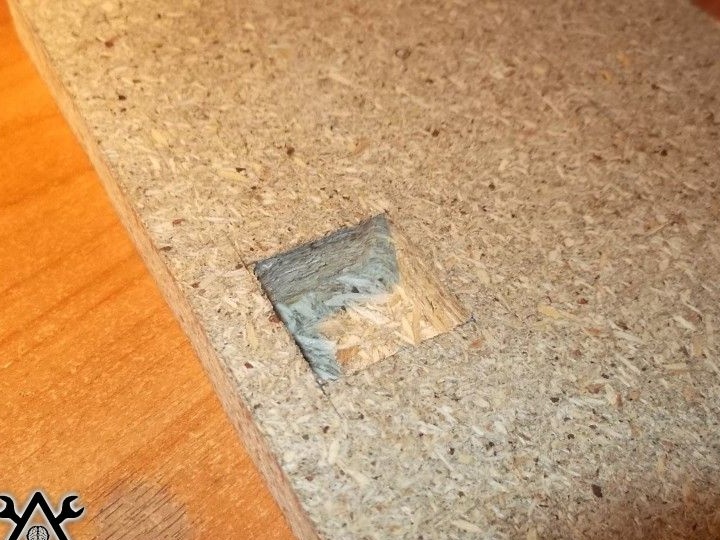
With the help of a cutter, he made a notch.

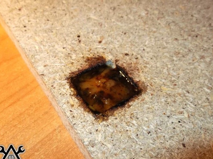
He put rosin in the recess and melted it with a construction hairdryer.

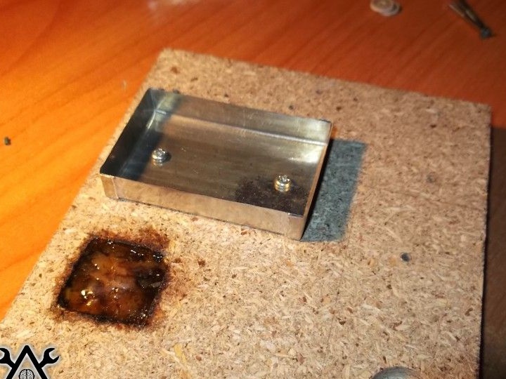
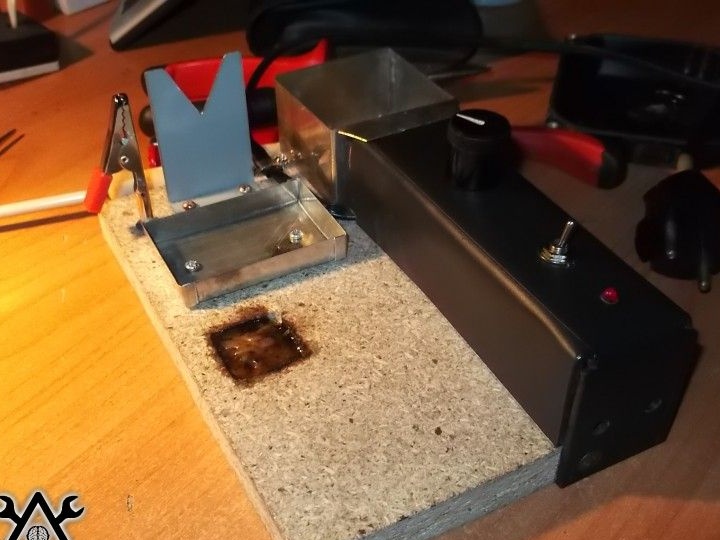
Secured a metal box stand and clamp.


Screwed the board.

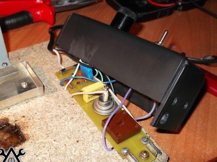
Replaced the board body.

Screwed the box for storing small things and an iron brush.

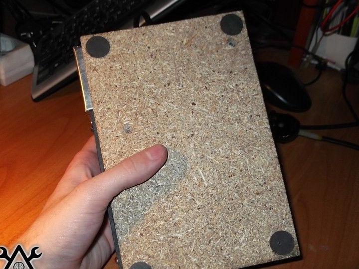
Cut out anti-slip feet from rubber. I glued them on the back of the stand.

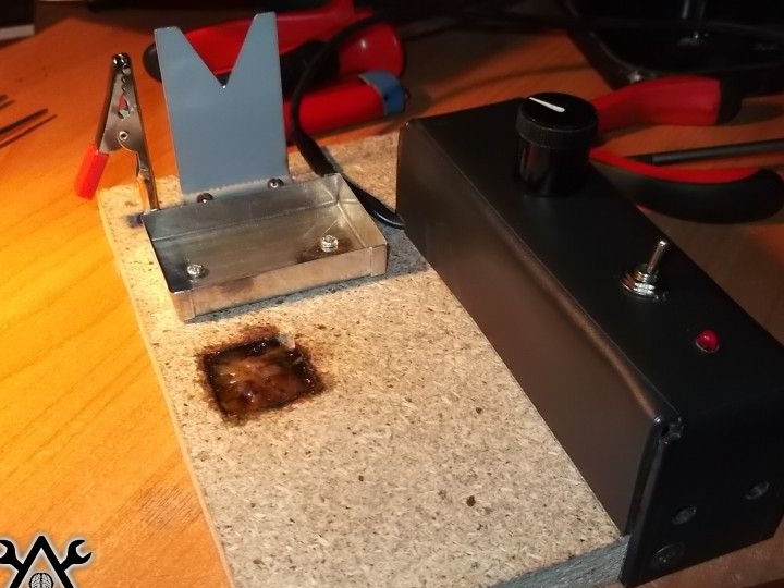
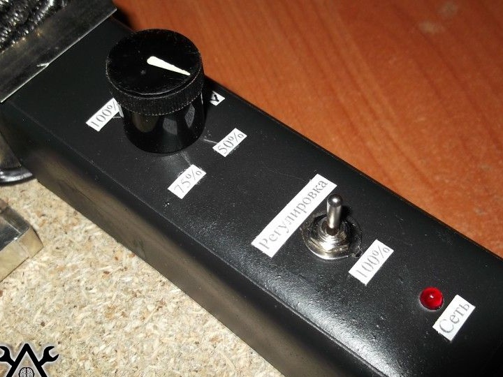
I printed, cut and pasted the inscriptions on the power adjustment board.

Soldering iron stand ready.
10
9.7
9.3

Add a comment

    • smilesmilesxaxaokdontknowyahoonea
      bossscratchfoolyesyes-yesaggressivesecret
      sorrydancedance2dance3pardonhelpdrinks
      stopfriendsgoodgoodgoodwhistleswoontongue
      smokeclappingcraydeclarederisivedon-t_mentiondownload
      heatirefullaugh1mdameetingmoskingnegative
      not_ipopcornpunishreadscarescaressearch
      tauntthank_youthisto_clueumnikacuteagree
      badbeeeblack_eyeblum3blushboastboredom
      censoredpleasantrysecret2threatenvictoryyusun_bespectacled
      shokrespektlolprevedwelcomekrutoyya_za
      ya_dobryihelperne_huliganne_othodifludbanclose
23 commentary
The table is not entirely true: in kilograms "k" is always a lowercase letter; E or R - only with "adversaries", with us - only face value without letters; gigaomas are indicated by the letter "G" (p.5.3.20 GOST 2.702-2011), G - again, the "potential enemy".
As far as I understand, I put you a plus. As for the designation of resistance without indicating units, these are only ohms and not kilograms at all: study the materiel (GOST 2.702), which I wrote about.
Kilooms without a letter are written only by illiterate pseudo-specialists.
Author

I found a table.
Author
Ivan on the diagram is written 47, perhaps by default it is Ohm. Although on some circuits I saw and write Ohm or kOhm. And about the minus you set or not I do not know. But in the comments on the source site the exact same question is unanswered. What did I write incorrectly?
Firstly, not "OM" and not "CoM", but "Ohm" and "Ohm."
Secondly, the diagram says: 47 Ohms. Read the regulatory documentation or, at least, read popular literature for amateur radio enthusiasts.
Author
The author is silent at the source and does not answer such a question.
Oh, do not tell me on the diagram? R5 at 47 ohm or 47 kohm
A stand .... Recently, there are cast-iron on sale with a "spring" for a soldering iron ... I bought these ones - very convenient. Samopaly threw.
... And the regulator (IMHO) is not needed. I do not need it - my soldering iron does not stand on from morning till night, like professional "soldering irons". And if you want to "turn it on, heat up, solder, turn it off," then the regulator is superfluous, agree ...
Well, you see, about phenols - this is superfluous .... Then soldering is harmful! And the acid boils and you hit the insulation - the vapors are released ....)))))
.... Yes, and breathing is generally harmful! )))))
Author
And I went to the page and answered everything and only after the update I saw your post.
I would not call it cumbersome: the size is approximately 100X150.
From the text and the diagram, which is not drawn correctly, it is not clear that the toggle switch has a neutral position, in which there is a complete disconnection from the network.
When heated, phenol is released much more actively, and the contact of the sting with the stand is inevitable: rosin is in the recess in the same place, and sometimes it is much more convenient to service the conclusions not on weight but on the surface.
I apologized for the error 13 minutes before you wrote. I apologize for my carelessness once again. ((
Author
This is the idea, in the hole and the rope. Have you seen a lot of this? Stuffed with shops with such knives
What is unsuccessful? Everything is compact. You need to separately remove the soldering iron from the regulator. In the end, you can do it on the board if you don't like chipboard.
This is the idea, in the hole and the rope. Have you seen a lot of this? And supplies ... a dime a dozen, all sorts. This is done unsuccessfully, starting from chipboard, a "dumb" electronic controller, unnecessary bulkiness (the floor of the table will take). But this is yours, there is no other.
Author
life-threatening: the network cable is not sealed tightly, is not connected to the regulator by a female part, but is connected to the regulator sockets by a plug! And where do you see the plug to the network? There is a wire with a plug to the network, and on the other hand, a plug for connecting a soldering iron
Author
The copyist did not bother to mention a significant detail: When you describe a scheme you don’t like it, you don’t like it, you bring it in its pure form again, not like that.
Author
when exposed to a soldering iron, it will not emit decomposition products of phenolic compounds. So do not poke a soldering iron in the chipboard for this there is a stand. Even if you poke, I don’t think there will be anything dangerous there. Around you there are so many objects with phenol that chipboard is seeds.
Author
This is your homemade product.
What is the idea to drill a hole in a knife and tie a rope?
Ugh you! I apologize: everything is done correctly with the connection, the last paragraph was written by me wrongly: I looked in the wrong direction, but editing is no longer possible!
I agree with Businessthat it’s better to use a board as a base: it will not crumble and will not release decomposition products of phenolic compounds when exposed to a soldering iron.
The copyist did not bother to mention a significant detail: the toggle switch is three-position, in the middle position it is disconnected from the network (otherwise the purpose of the toggle switch section S2 is not clear). The toggle switch is generally incorrectly marked: as if there are two of them.
But home this is not the ambush of the product - the design of the regulator life threatening: the network cable is not tightly sealed, is not connected to the regulator by a female part, but is connected to the regulator sockets with a fork!
Stand for yourself, regulator for yourself ... The base is better to make from simple wood, and not from chipboard.
What is the idea? Screw the knob to the stand?

We advise you to read:

Hand it for the smartphone ...