
When using ordinary “dynamos” for a bicycle, the question of their durability always arises. Indeed, in such a device, the rotor rotates, as a result of which friction occurs in the bearings (or bushings), which subsequently destroys the generator. Also, excess friction leads to a loss of energy, i.e. bike the roll is not so far and more efforts are needed to disperse it.
The way out of this situation may be the use of a contactless generator. In such a device there are no rotating parts, and it can work almost forever. As a rule, the role of the rotor is played by the bicycle wheel itself, but the stator is attached to the frame or fork. The cost of such generators is quite high, so it makes sense to try to create it yourself.
Below we will consider the simplest way to create a contactless generator for a bicycle. But it is only model, a principle that can be taken to create similar homemade.
Materials and tools for homemade:
- a powerful magnet (the author uses a neodymium from the hard drive);
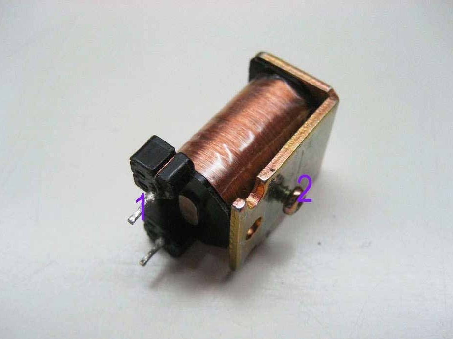
- three coils (you can do it yourself);
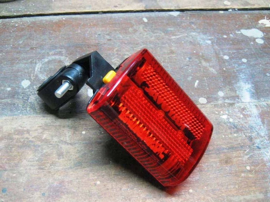
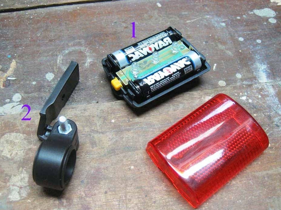
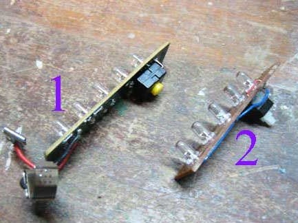
- taillight with three LEDs;
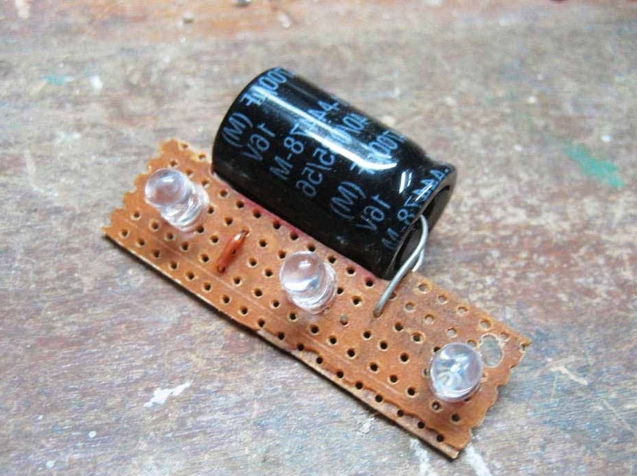
- 4700 nF capacitor;
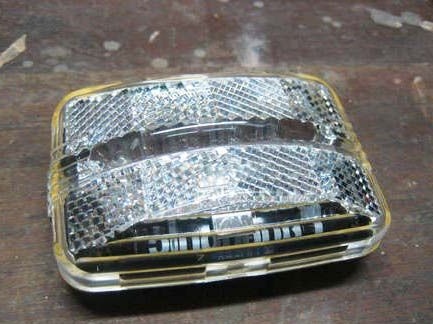
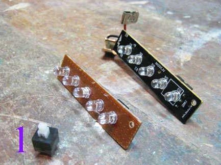
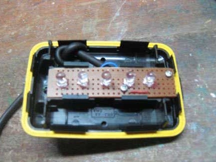
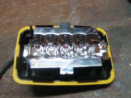
- headlight (with five white LEDs);
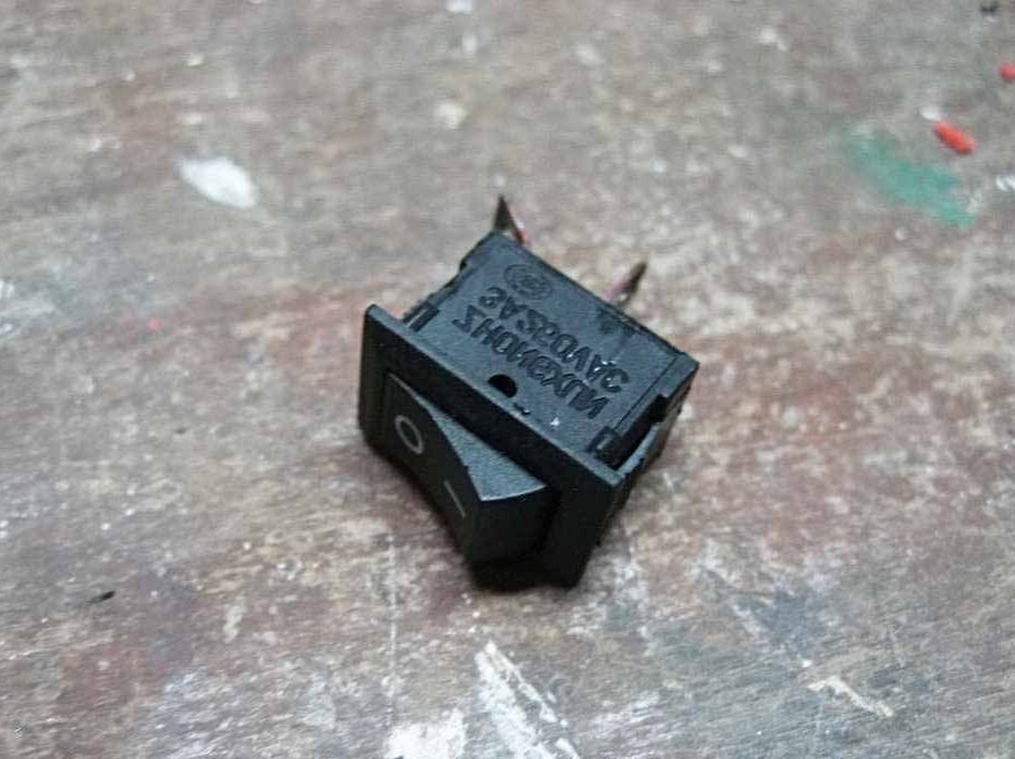
- double switch from a computer power supply;
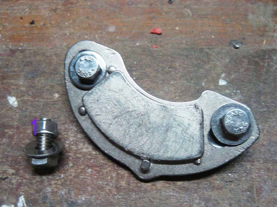
- two screws with nuts and washers (for attaching the magnet to the wheel);
- screwdrivers and wrenches, soldering iron, electrical tape;
- wires, switches and other little things.
Generator manufacturing process:
Step one. Installing generator elements on a bicycle
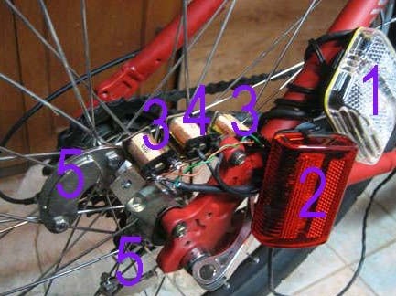
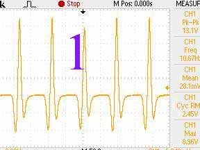
Everything works according to a very simple scheme. A powerful neodymium magnet is attached to the bicycle wheel with two screws and nuts from the computer’s hard drive (The author uses three magnets, this allows you to remove vibrations. You can use more). Opposite it, a coil is placed at a minimum distance to the bicycle fork; when a magnet passes near it, a current arises in it. The author of the coil has three, one is needed for the taillight, and two for the front. Since the current is pulsed, the lights will flash when driving. The closer the magnet passes near the coil, the more it can generate energy.
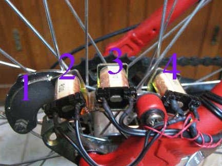
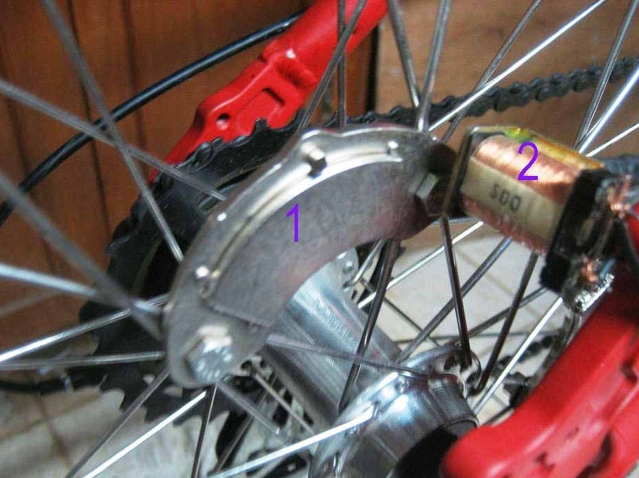
Coils can be wound either by yourself, or you can find one already ready, for these purposes old relays will do. Ideally, the resistance of the coil should be 100-200 ohms, but the author uses two coils of 600 ohms each and says that everything works fine.The higher the resistance of the coil, the more it will generate energy, but at the same time, the efficiency decreases due to losses in the coil. It is advisable to come up with some kind of housing for the coils, or else protect them from water and dirt.
If everything is done correctly, then when the wheels rotate, the coils will already generate pulse voltage.
Step Two Connect the rear light
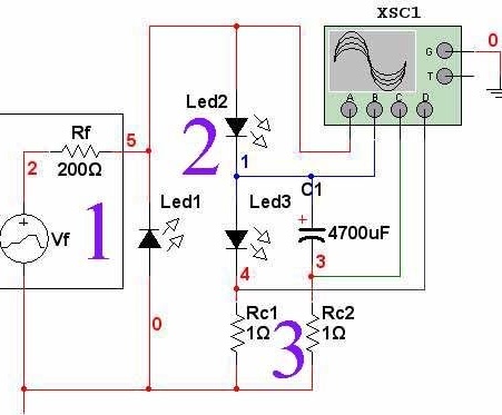
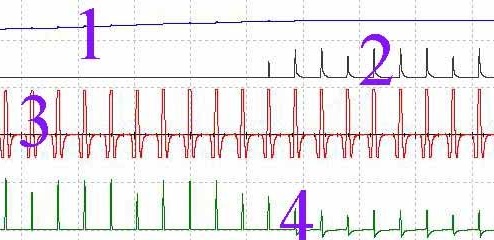
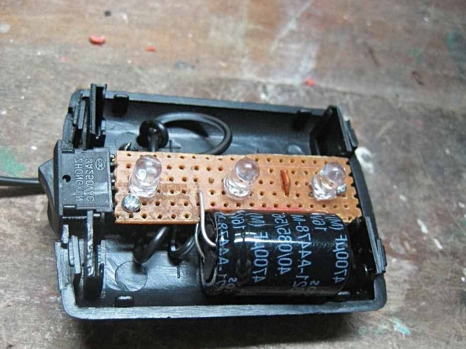
The front and rear lights in the system are completely independent. The taillight is powered by just one coil. In order to stabilize the voltage a little, a 4700 nF capacitor is provided in the circuit. The initial voltage here is 2.2 Volts. How exactly the voltage is generated by the coils can be viewed on an oscilloscope.
With a full turn of the wheel, there should be three pulses, since the system has three magnets.
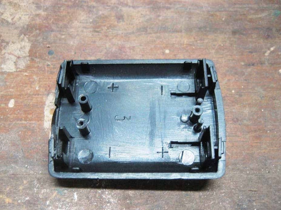
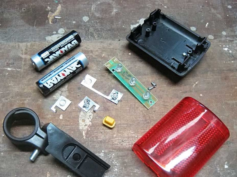
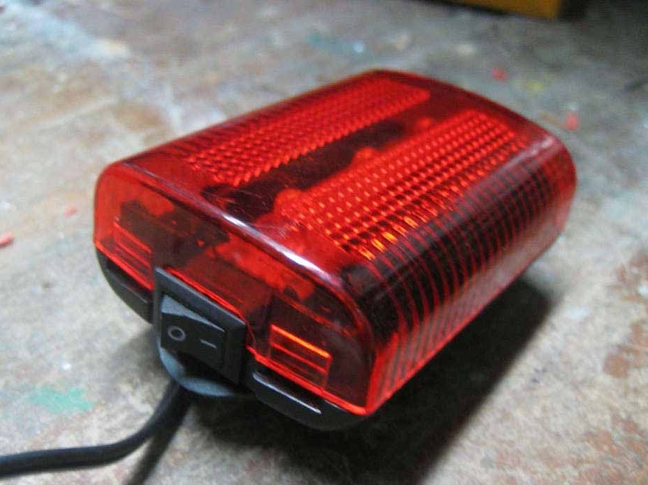
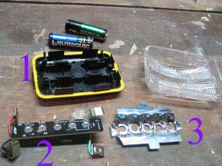
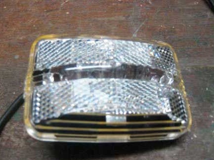
To connect the flashlight, you need to disassemble it. You need to remove the batteries from it, because they are no longer needed here. Instead of batteries, you need to install a capacitor in the flashlight. After the flashlight is assembled, it can be mounted on a bicycle and then connected to one of the coils using a two-wire cable. When the wheel rotates, the taillight should start flashing.
Step Three Front light connection
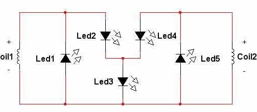
The headlight is powered by two coils, here the author installed five white LEDs. The layout is designed in such a way that when driving the headlight will also flash. A capacitor is not used here, but it can be installed in parallel with the “3” LED, because a negative voltage is never applied to it. Thus, when driving, one LED will constantly light, and three will flicker. Coils do not generate energy at the same time, if they are connected in series, then one coil will absorb part of the energy of another, in this circuit everything works differently.
Well, then everything is connected as in the case of connecting a taillight. After assembly, you can try to test the system. It is important to understand that the faster the bike moves, the more the generator will generate energy, and this can lead to burnout of the LEDs. So for the future it is important to come up with a circuit that will limit the current supply to the LEDs.
Needless to say, the circuit can be further developed, for example, install a small battery and make a circuit for charging it. But the main goal is to build a non-contact generator for a bicycle, here has been successfully achieved. The only drawback is that various metal objects can be attracted to the magnets when driving, so it is best to place the magnets as close to the center of the wheel as possible.