

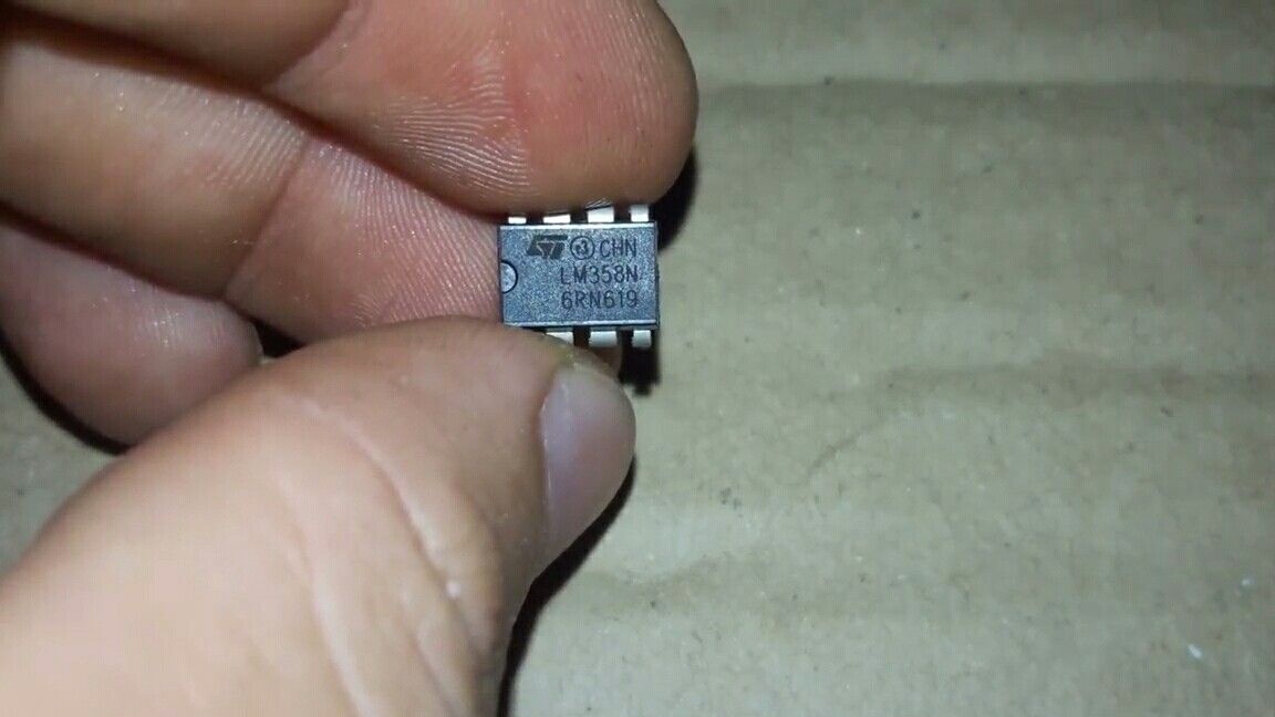
So let's get started. First you need to decide on the components and circuitry. The principle of operation of the circuit is simple: a weak signal from the microphone is amplified and sent to the Arduino analog pin. As an amplifier I will use an operational amplifier (comparator). It provides a much higher gain compared to a conventional transistor. In my case, the LM358 chip will serve as this comparator, it can be found literally anywhere. And it costs pretty cheap.
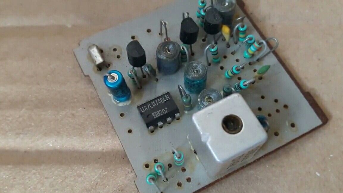
If you could not find the LM358, then in its place you can put any other suitable operational amplifier. For example, the comparator shown in the photo stood on the amplifier board of the infrared receiver signal in the TV.
Now let's look at the sensor circuit.

In addition to the operational amplifier, we will need a few more easily accessible components.
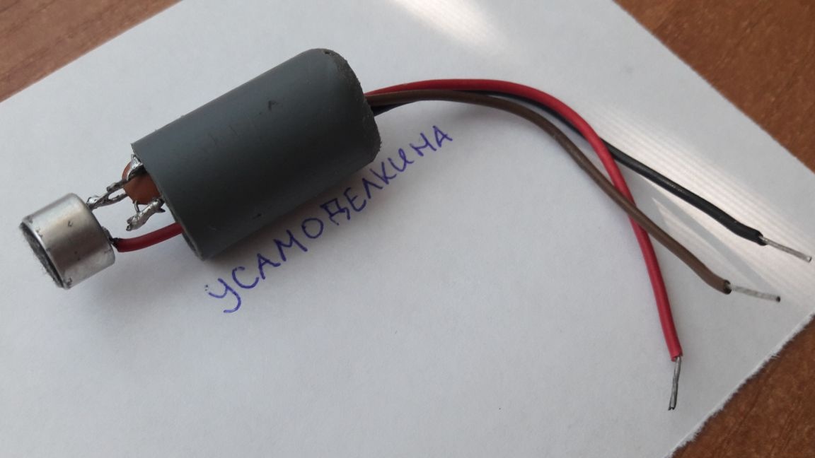
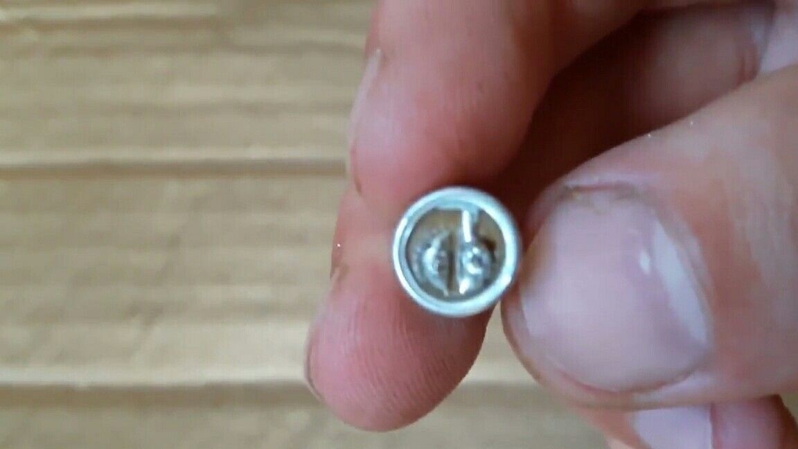
The most ordinary microphone. If the polarity of the microphone is not indicated, then just look at its contacts. The minus one always goes to the case, and in the circuit, accordingly, it is connected to the "ground".
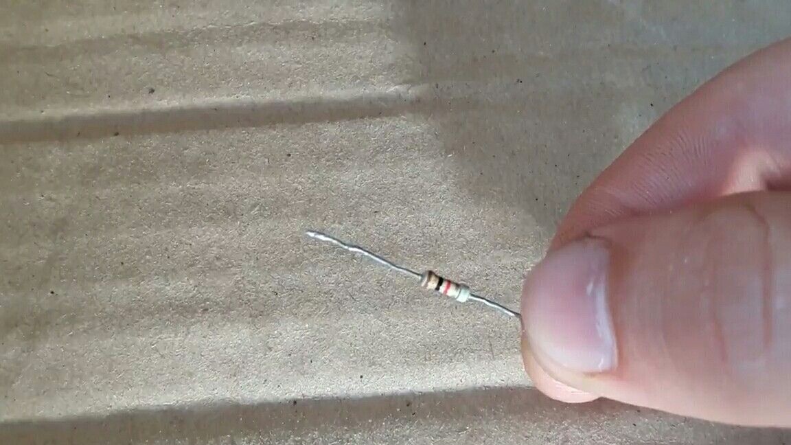
Next, we need a 1 kΩ resistor.
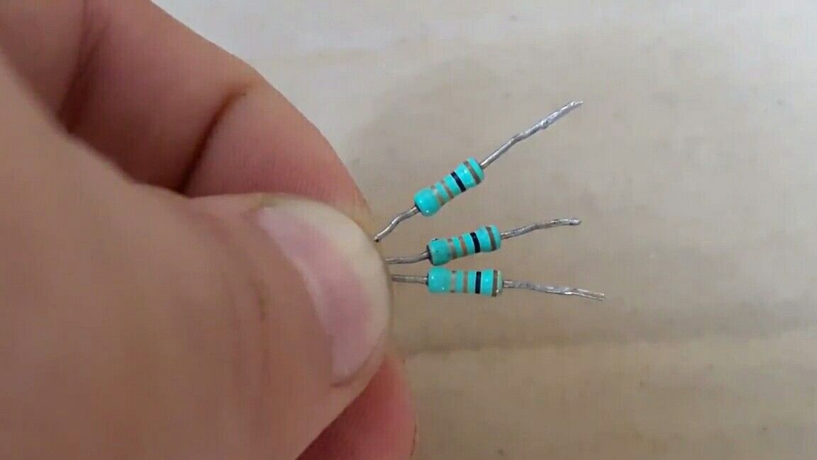
Three 10 kΩ resistors.
And another 100 kΩ resistor is 1 MΩ.
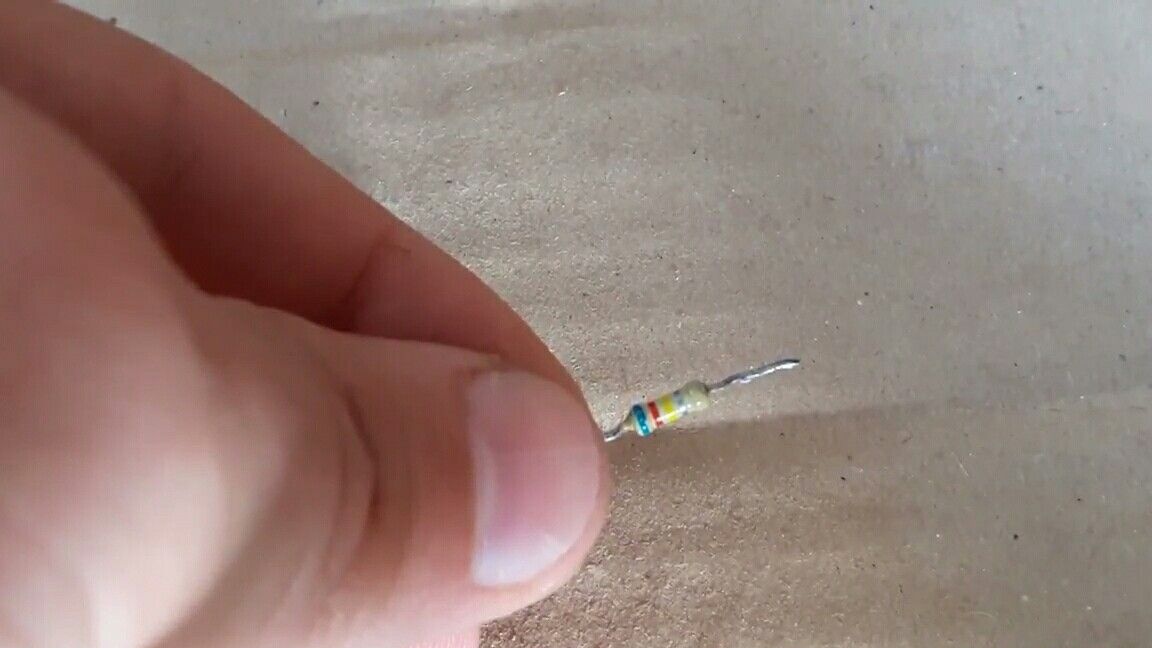
In my case, a 620 kOhm resistor is used as the “golden mean”.
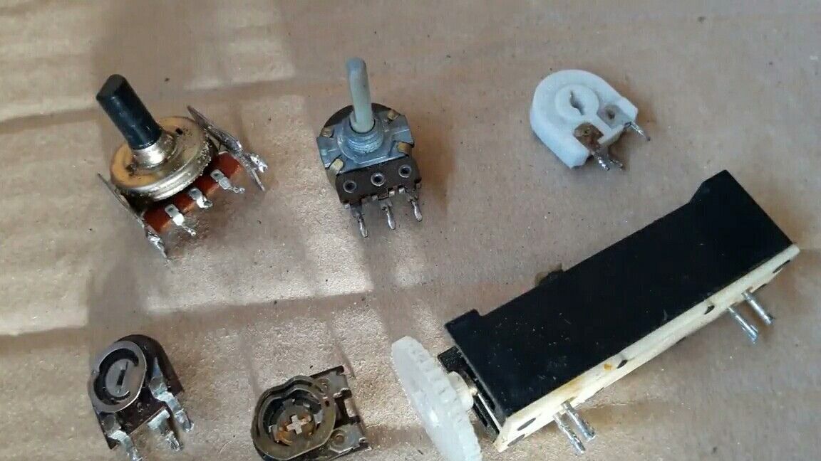
But ideally, you need to use a variable resistor of the appropriate rating. Moreover, as shown by experiments, a larger rating only increases the sensitivity of the device, but more “noise” appears.
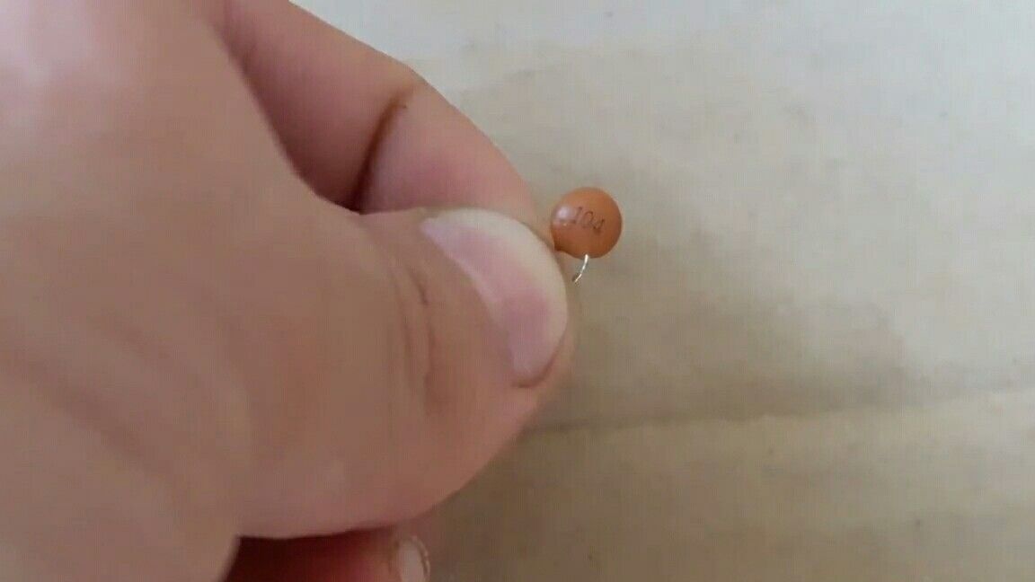
The next component is a 0.1 uF capacitor. It is labeled "104".
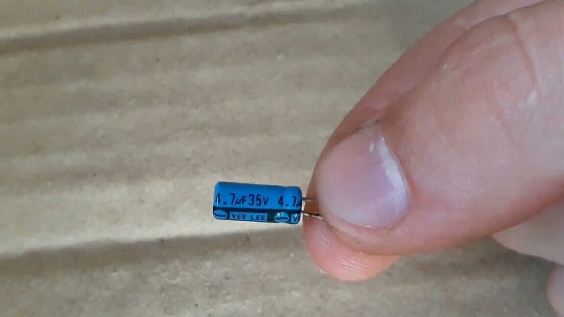
And another capacitor, at 4.7 uF.
Now we pass to assembly. I assembled the circuit with a mounted installation.
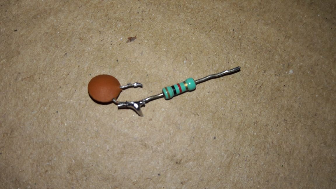
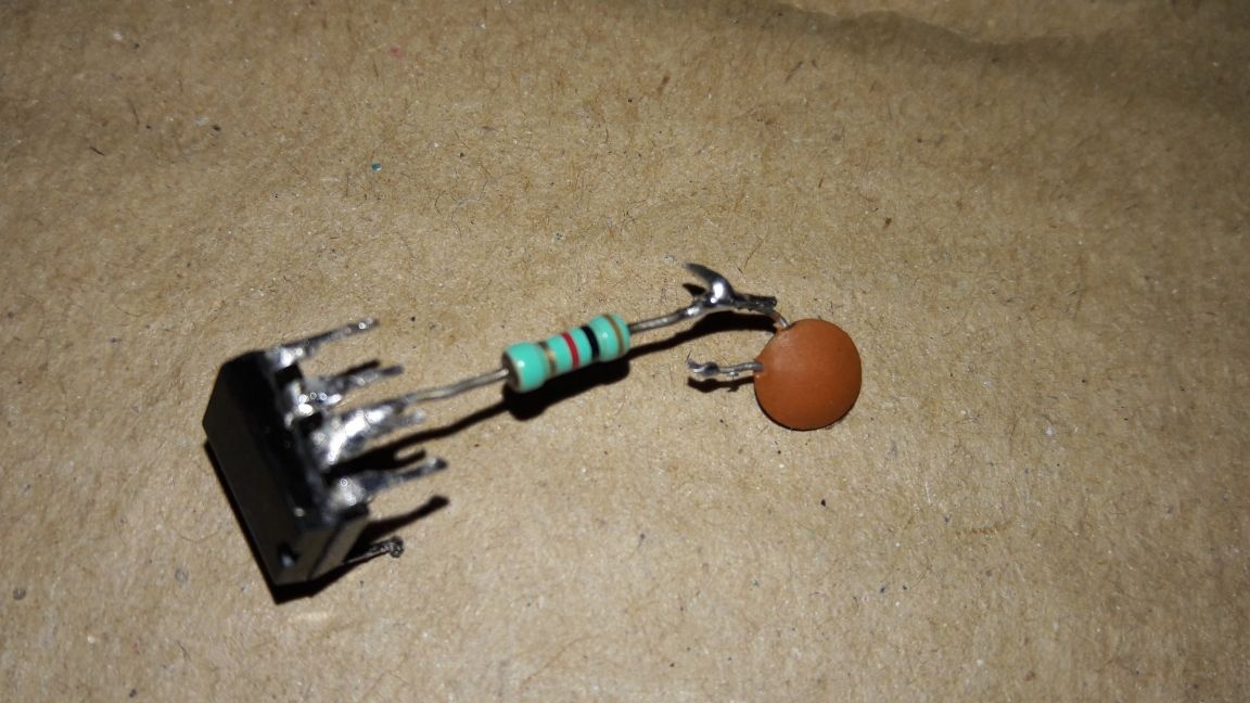
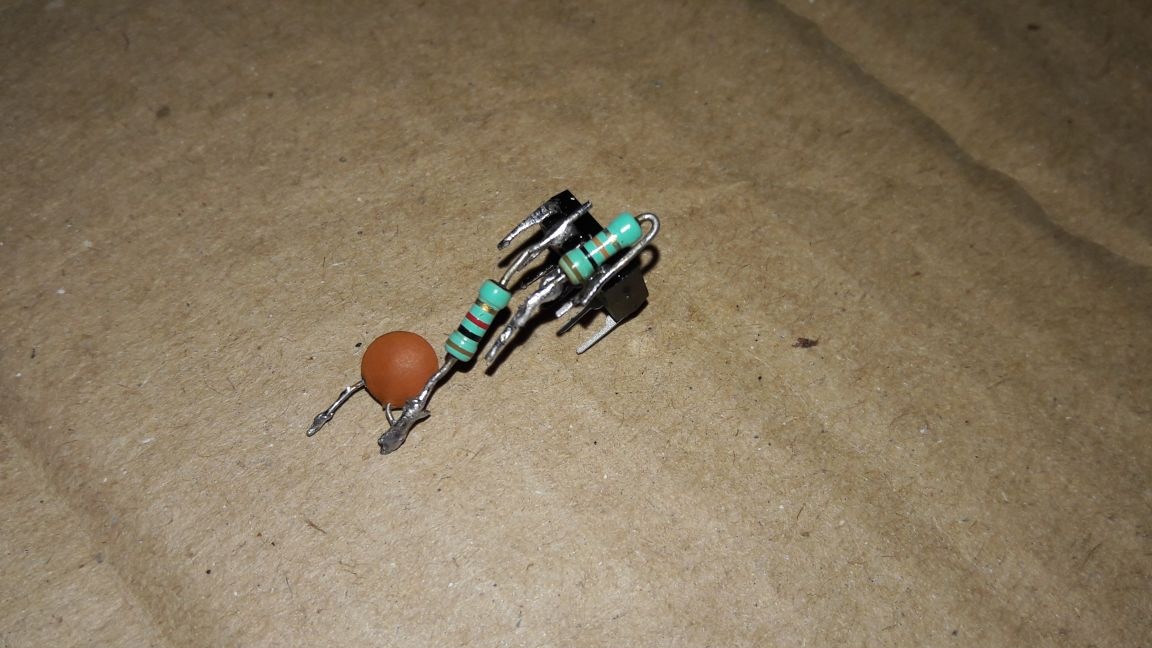
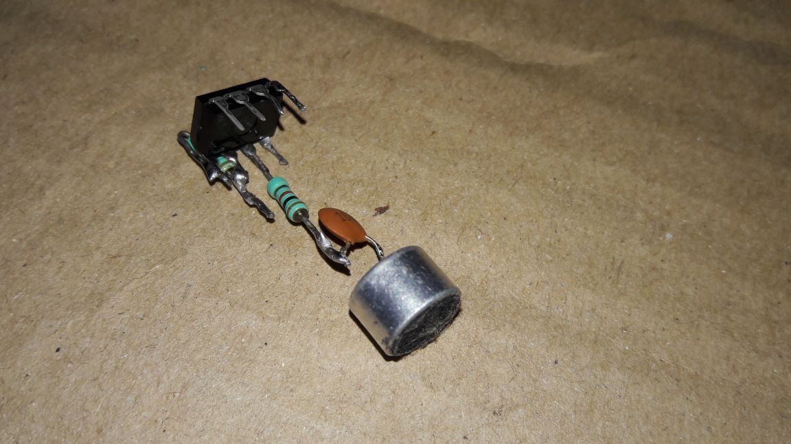
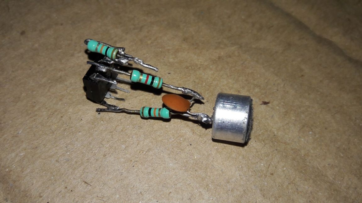
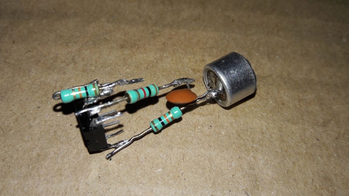
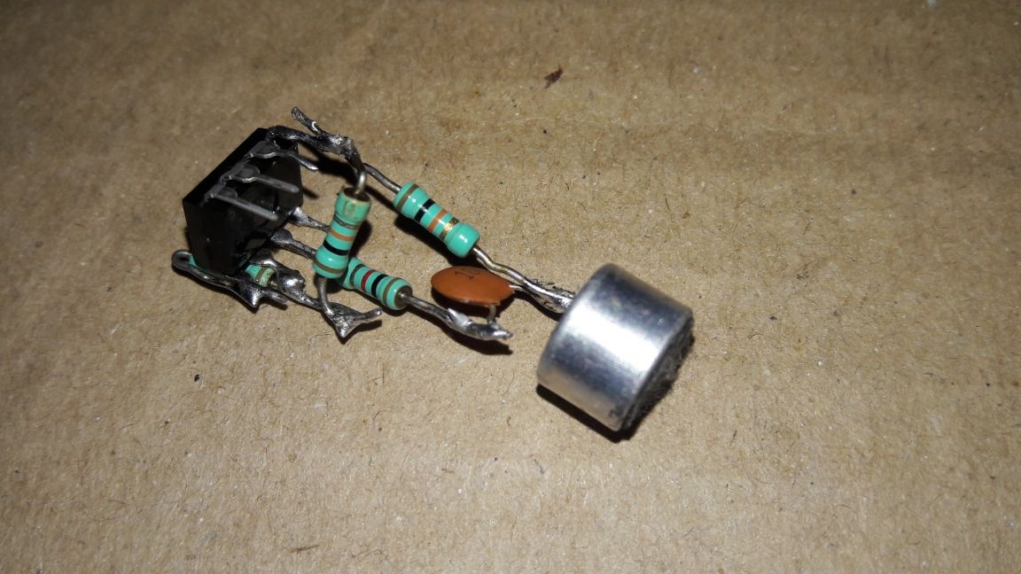
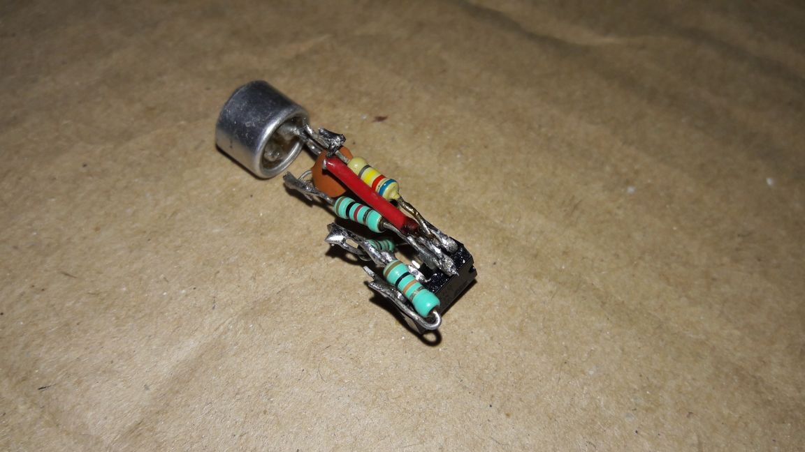
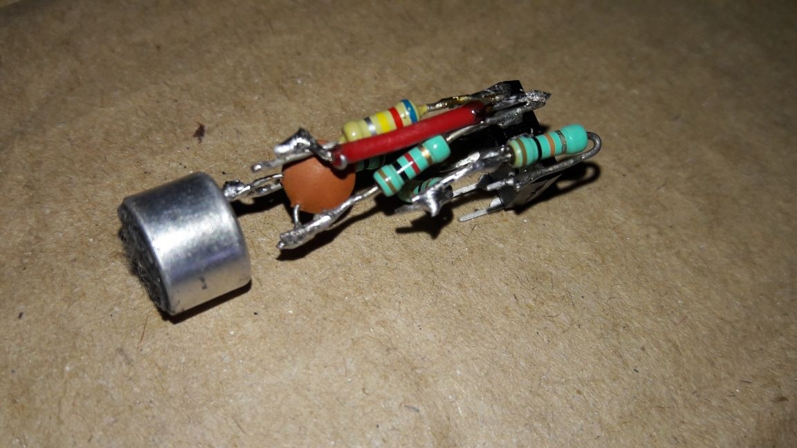

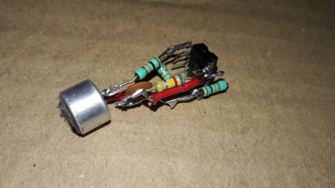
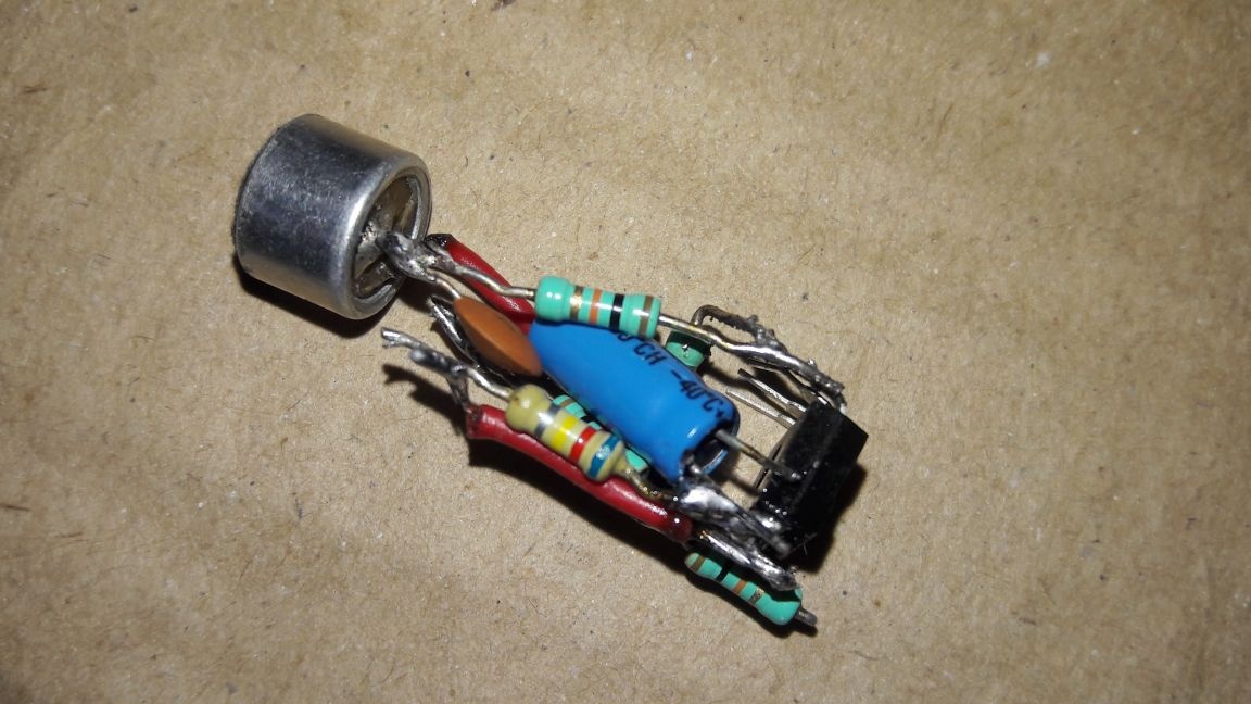
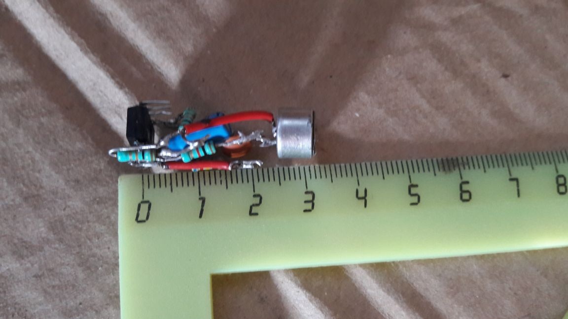
Assembly completed.I installed the circuit in a case that I made from a small piece of plastic tube.
We proceed to testing the device. I will connect it to the board Arduino UNO. We move into the Arduino development environment and open the AnalogReadSerial example in the Basics section.
void setup () {
Serial.begin (9600); // connect the Serial connection at 9600 baud
}
void loop () {
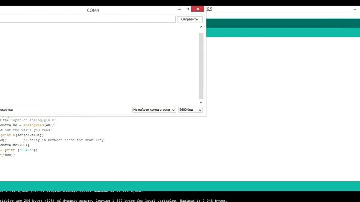
int sensorValue = analogRead (A0); / * read the value from the zero analog pin and save it in the variable sensorValue * /
Serial.println (sensorValue); // output the value to the port
delay (1); // wait one millisecond for stabilization
}Before loading into the board, we change the delay by 50 milliseconds and load it. After that, we make a test cotton and follow the indications. At the time of clap, they jump, try to remember this value approximately and return to the sketch.
Add a couple of lines to the sketch.
if (sensorValue> X) {
Serial.print ("CLAP");
delay (1000);
}
Instead of “X”, insert the same value, load and clap again. So continue until you find the optimal response value. With an overestimated value, the condition will be fulfilled only with cotton at a very close distance. With a lower value, the condition will be satisfied at the slightest noise or the sound of steps.
Also, with the correct selection of the resistor R5, this sensor can turn into a digital one and can be used in hardware interrupts. The potential of this design is huge, on its basis you can assemble a bunch of various projects, and its simplicity makes the device accessible to everyone.
In conclusion, I propose to watch a video in which everything is clearly shown. The calibration process and assembly of the simplest cotton switch are also explained in much more detail.
I hope you enjoyed it. I wish you a successful assembly!