
To facilitate cycling and make it safer, many motorists in every way modify their faithful iron horses. Today we will talk about such homemadelike turn signals. Equipped bike With such a device, there is no need to take your hand off the steering wheel and show where you intend to turn. Now everything will work as if on car or a motorcycle, it’s worth turning on the desired switch and the corresponding indicator starts to light up behind the bicycle. So, let's start the process of creating homemade products.
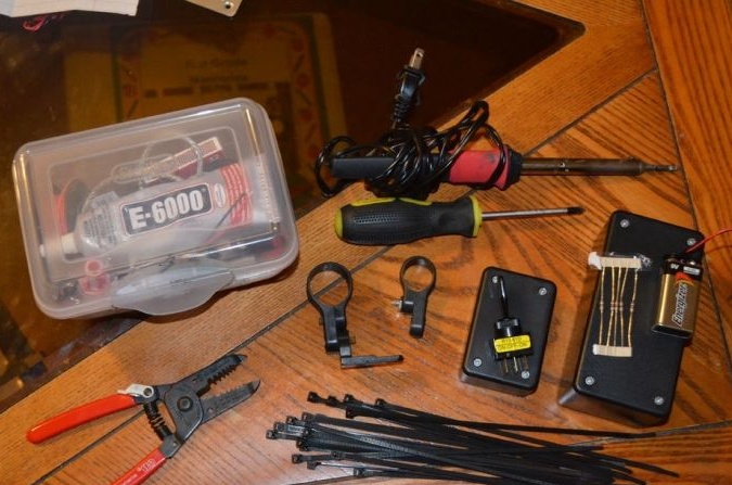
Materials and tools for home-made turn signals:
- case measuring 9x4x4 cm;
- clamps or straps with Velcro (3 pieces);
- one case measuring 12.5 x 6.5 x 5 cm;
- two 10 ohm resistors;
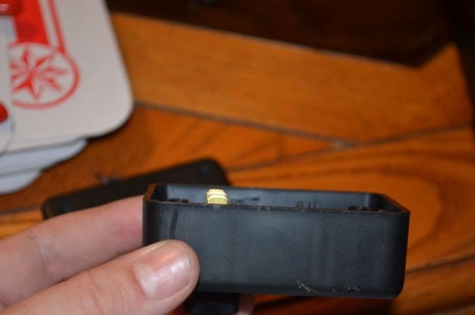
- one connector for the Krona battery;
- switch type SPDT;
- yellow LEDs 5 mm (in order to be able to use a 9V battery, you need 10 LEDs for 1.8 V);
- ten holders for LEDs;
- one 9V battery;
- two holders for reflectors;
- superglue or glue gun;
- drill with drills;
- bolts;
- screwdriver;
- soldering iron with solder.
Turning process:
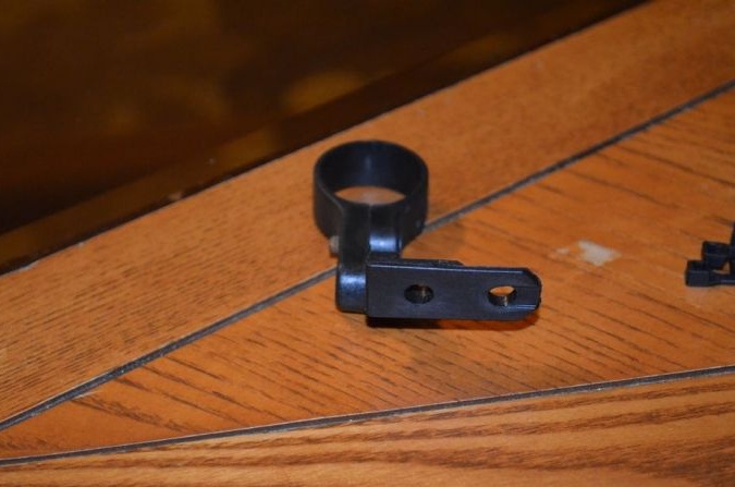
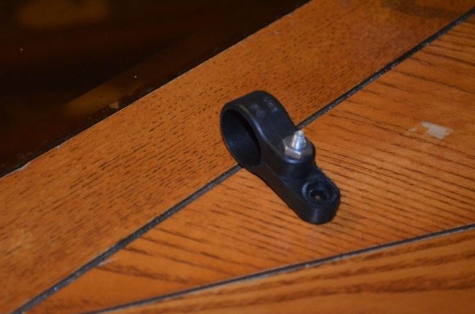
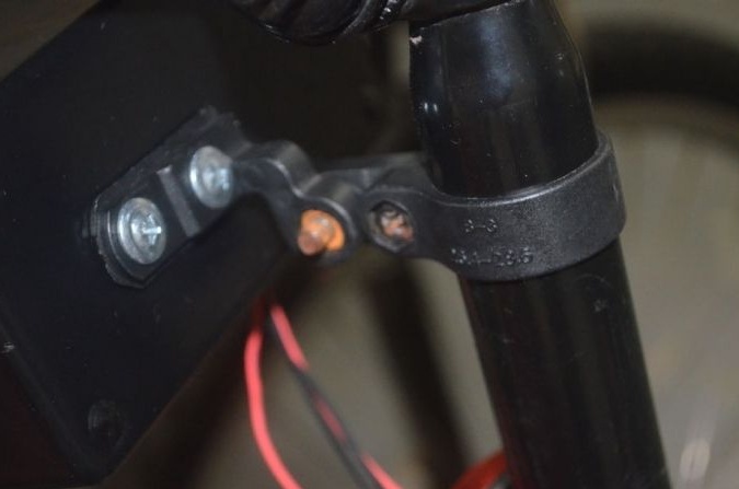
Step one. Disassemble reflectors
The author begins by disassembling the reflectors, thereby we get the necessary fasteners. Since the reflectors are different, it is already necessary to act at your discretion. In order to get one rear mount, the author combined elements from two mounts. The result should be one front mount and one rear.
Step Two Switch Block Fabrication
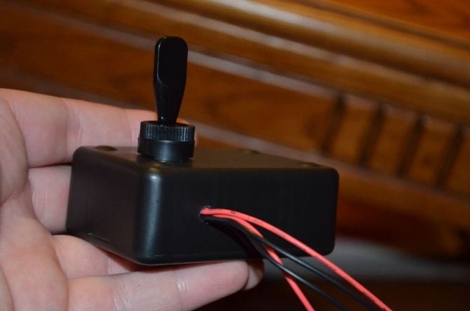
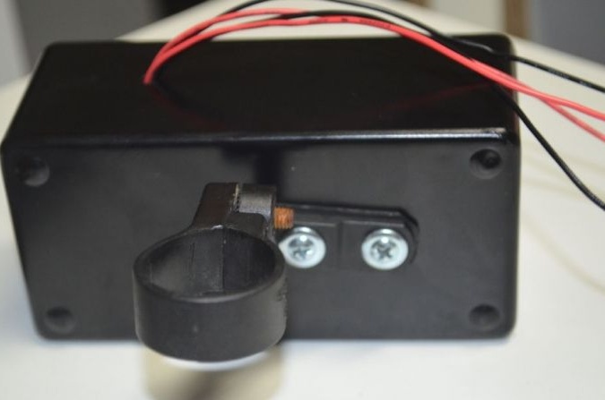
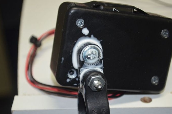
The power supply (9V battery) as well as the SPDT toggle switch will be located in the switch block. First of all, you need to decide how the body will be fixed to the bicycle. The author decided to install the block on the left, he fastens with bolts.
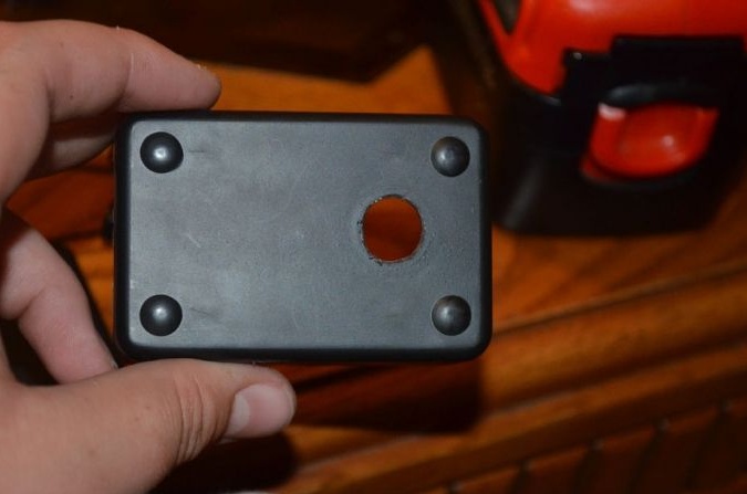
In order to install the toggle switch, in the case you need to drill a hole in a suitable place. Plastic is drilled very easily, so it is important not to overdo it. Next, the toggle switch is inserted into the hole, installed in the desired position and fixed with a nut.
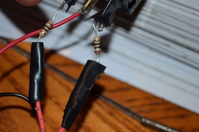
Next, the toggle switch needs to be connected, it is connected through resistors, as seen in the photo. The middle contact of the toggle switch must be connected to the plus of the battery. As for the value of the resistors that are soldered to the side contacts, it is 10 ohms. Then you need to solder the wires to the resistors.In length, they must be such that they can reach the rear reflector; an additional margin of 15 cm must be added to this length. It is most convenient to mount using a heat-shrink tubing.
To the "ground" of the battery connector you need to solder two more wires of exactly this length.
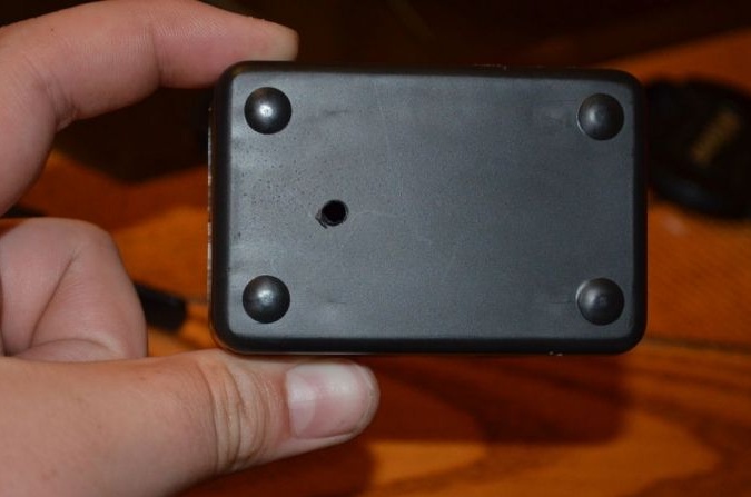
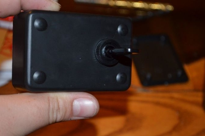
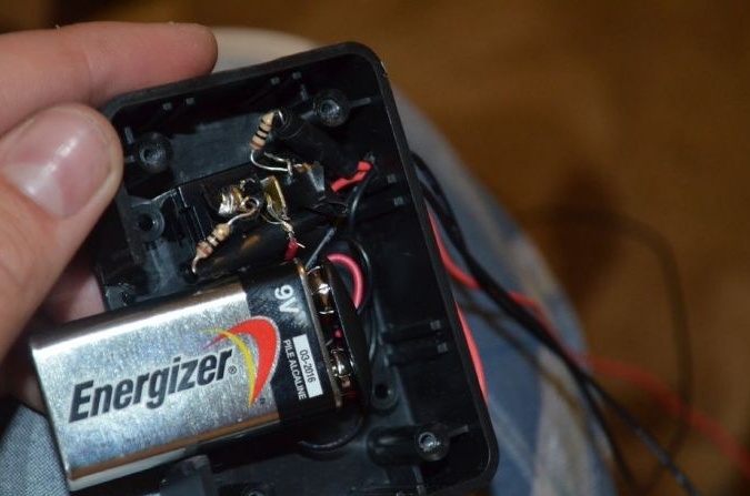
To bring out the wires, you need to drill a small hole in the housing. Well, then everything is going, the battery is installed inside, and the toggle switch is securely fixed with a nut. In conclusion, the case closes.
Since the author’s battery did not fit in the case, he used a dremel to cut out a groove so that some of the batteries stick out.
Step Three LED assembly
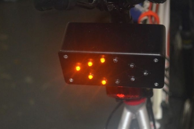
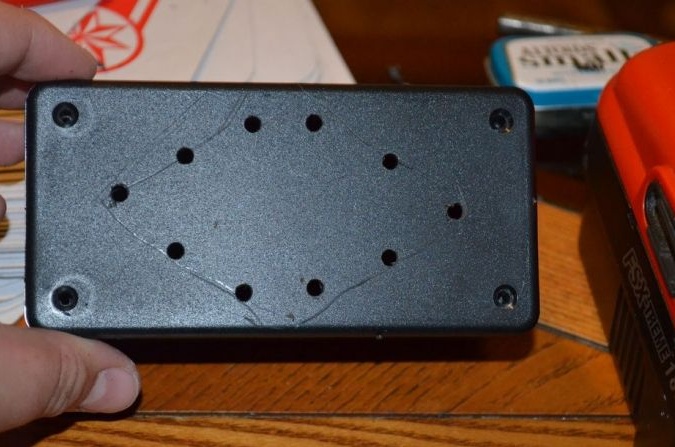
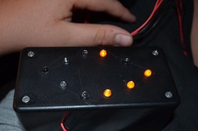
Now you need to take a large case and proceed with the installation of LEDs. First you need to mark it, for this you will need a ruler and some sharp object, for example, an awl or a carnation. After marking, you need to outline places for ten LEDs on the case. Five LEDs will be used to indicate a turn to the right, and five to the left. The distance between the diodes should not be too small, otherwise the LED holders will touch.
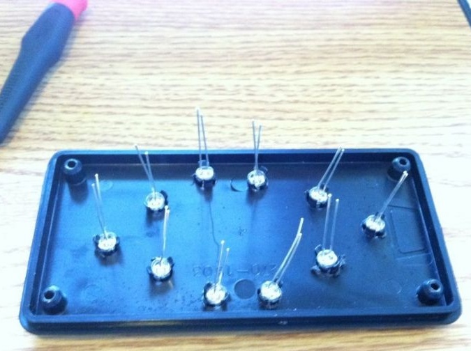
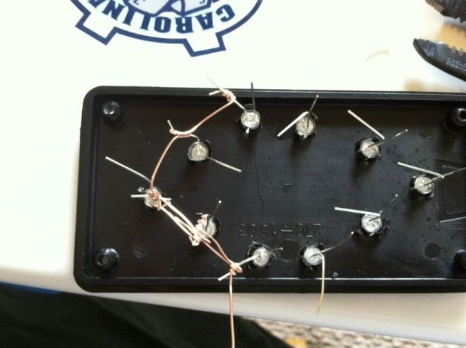
After the holes have been drilled, the LED holders can then be inserted into them, and then the diodes themselves can also be installed in the holders. It is necessary to install the LEDs so that all their “negative” contacts are deployed in one direction, and the “plus” ones in the other. For additional fixation of the LEDs, glue can be used.
All the "plus" contacts of the LEDs can now be bent.
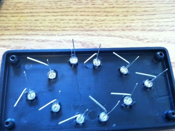
Next, you need a wire, with it you need to connect all the "plus" contacts of the LEDs of the same arrow. A similar operation is carried out with the second arrow. In this case, do not forget to leave two long ends for connecting wires.
Next, the same operation must be done with the negative contacts of the diodes, as a result, 4 contacts should be obtained, that is, two on each arrow. In order to ensure reliable contact between the diodes and wires, the joints must be soldered.
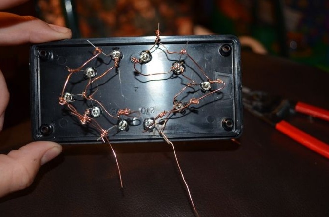
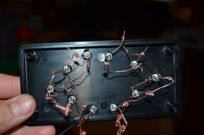
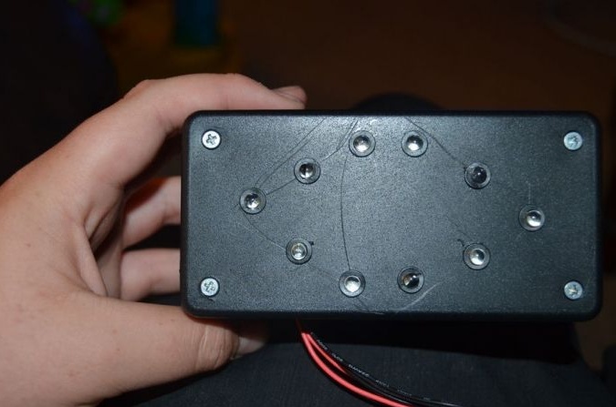
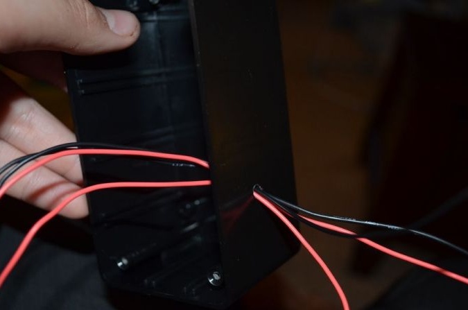
Then to the arrows you need to connect the wires coming from the previously made block with a toggle switch and a power source. To bring out the wires, you need to drill a hole in the housing. The joints must also be soldered for reliable contact.
After assembly, the system can be tested. If the arrow does not light, then the polarity may be reversed.
Step Four The final stage of assembly
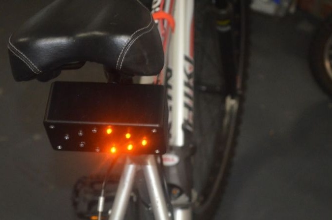
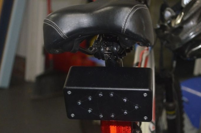
Now everything can be mounted on a bicycle. The housing with LEDs is mounted using a reflector mount. For the clamp, you can use a bolted connection, electrical tape, glue and so on. When working with a dremel, you need to be careful, as you can easily drill the body.
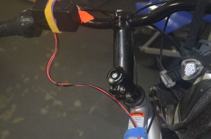
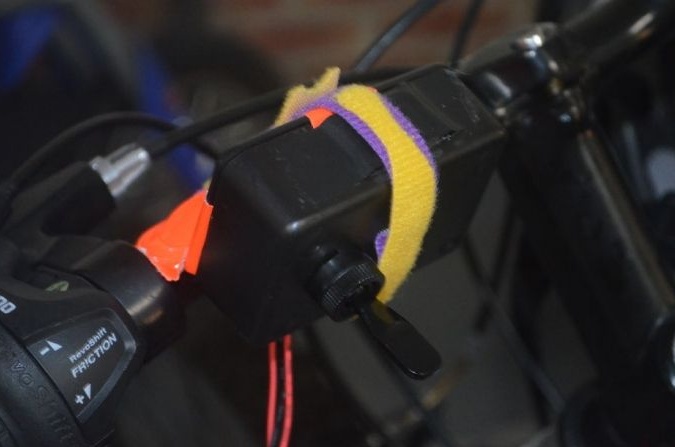
As for the box with the switch, it needs to be fixed on the steering wheel so that when you turn on the toggle switch down the left arrow lights up, and when you turn on up the right arrow, well, or to your personal taste.
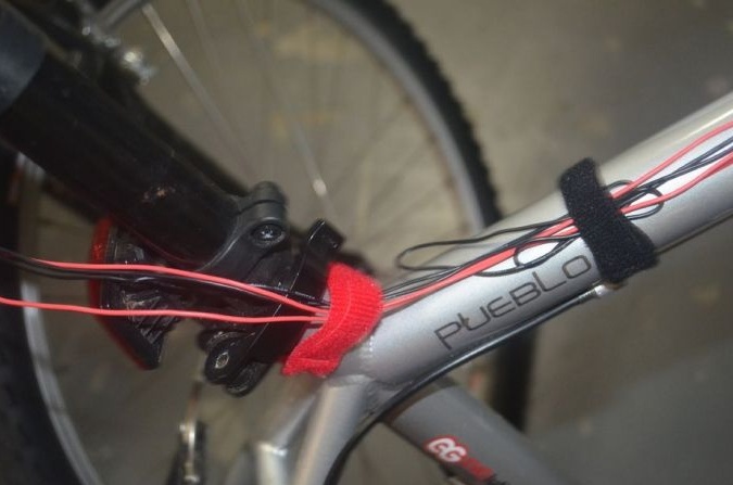
It is important to conduct and fix the wires well, otherwise it is very easy to break them when driving. For mounting, you can use plastic clamps, electrical tape and so on. It is important not to forget that the wire should have a certain margin in the steering wheel area, otherwise it will interfere with turning. If it so happens that the wire is too long, it can be twisted and placed in a case with LEDs, there is enough space there.
That's all, the turn signals are ready. Of course, in the future it is advisable to refine them, namely, to make them blink rather than burn monotonously. But this is a matter of technology.