

Due to the crazy pace of development of radio engineering and electronics towards miniaturization, more often when repairing equipment you have to deal with SMD radio components, which without enlargement, at times, are even impossible to consider, not to mention neat installation and dismantling.
So, life made me search the Internet for a device, such as a microscope, which could be made with my own hands. The choice fell on USB microscopes, which there are a lot of homemade products, but all of them cannot be used for soldering, because have a very small focal length.
I decided to experiment with optics and make a USB microscope that would satisfy my requirements.
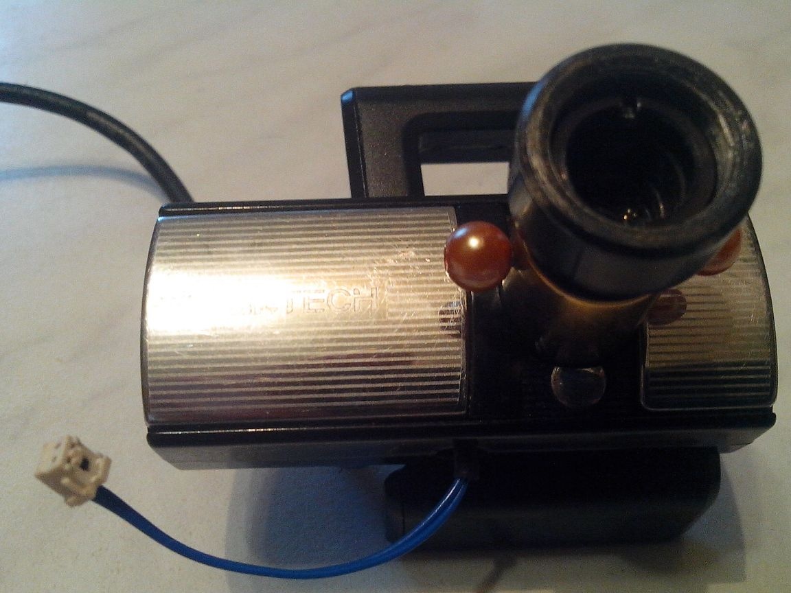
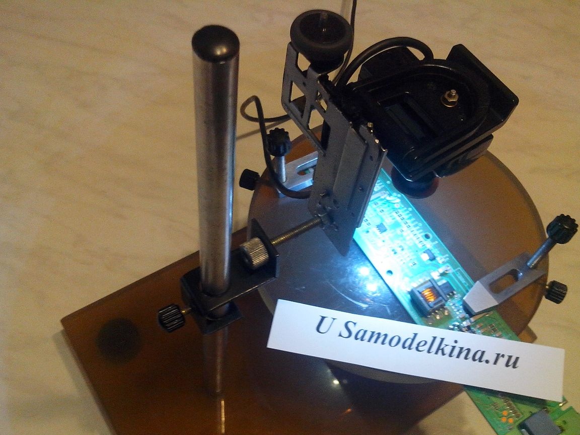
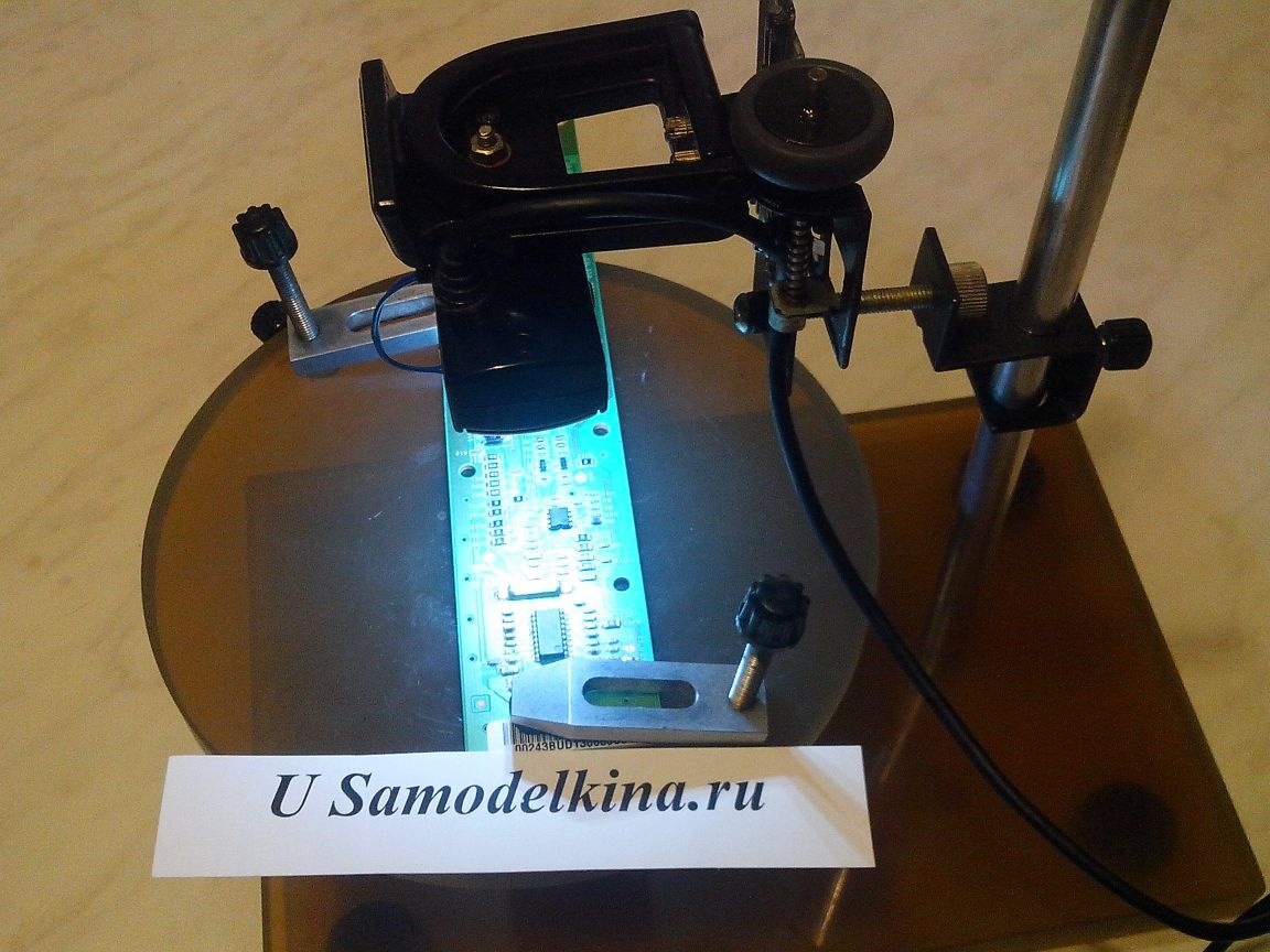
Here is his photo:
The design turned out to be quite complicated, so it does not make sense to describe in detail each step of manufacturing, because this will clutter up the article. I will describe the main nodes and their step-by-step manufacturing.
So, “without spreading thought through the tree”, we begin:
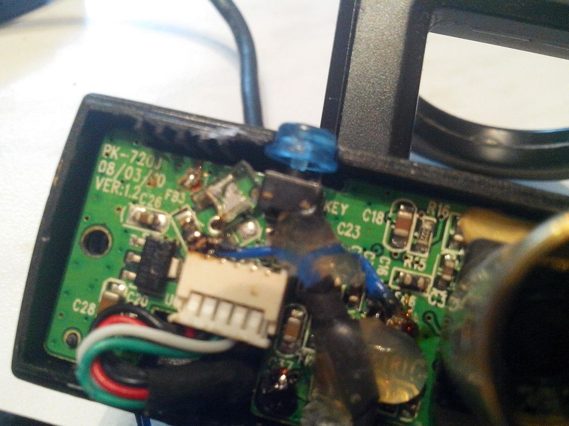
1. I took the cheapest A4Tech webcam, to be honest, they just gave it to me because of the fig quality of the image, which I didn't give a damn about, if only it was working. Of course, if I took a better and, naturally, expensive webcam, the microscope would turn out with better image quality, but I, as a master, act according to the rule - "For the lack of a maid, they" love "the janitor," and besides the image quality of my USB soldering microscope suited me.
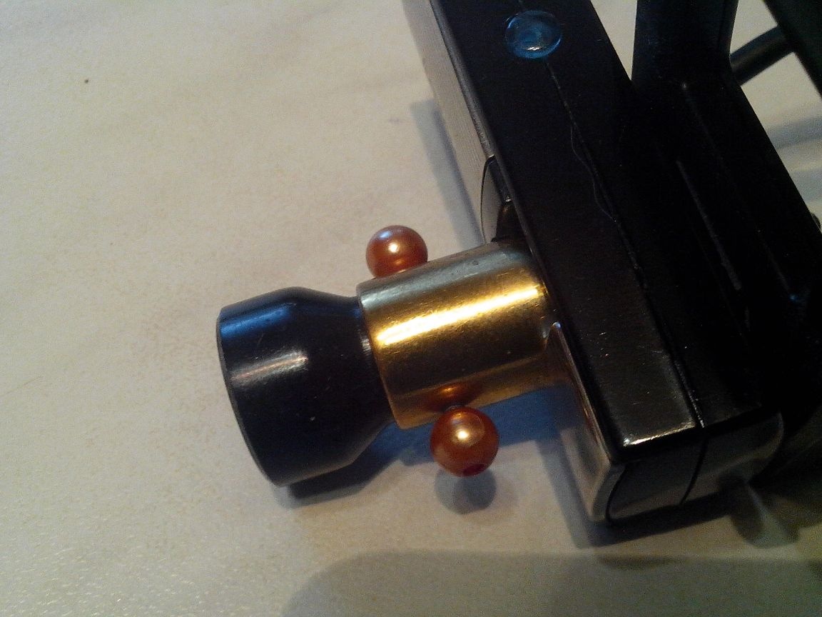
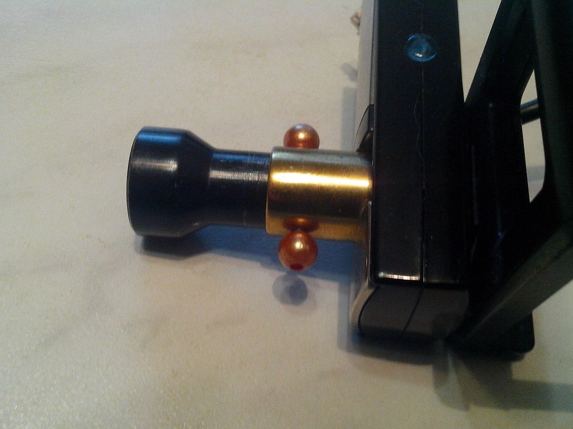
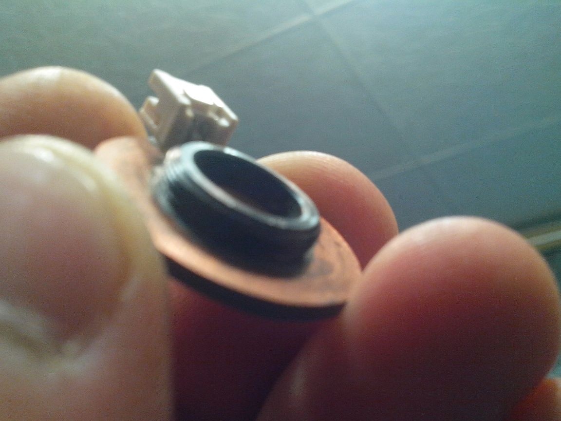
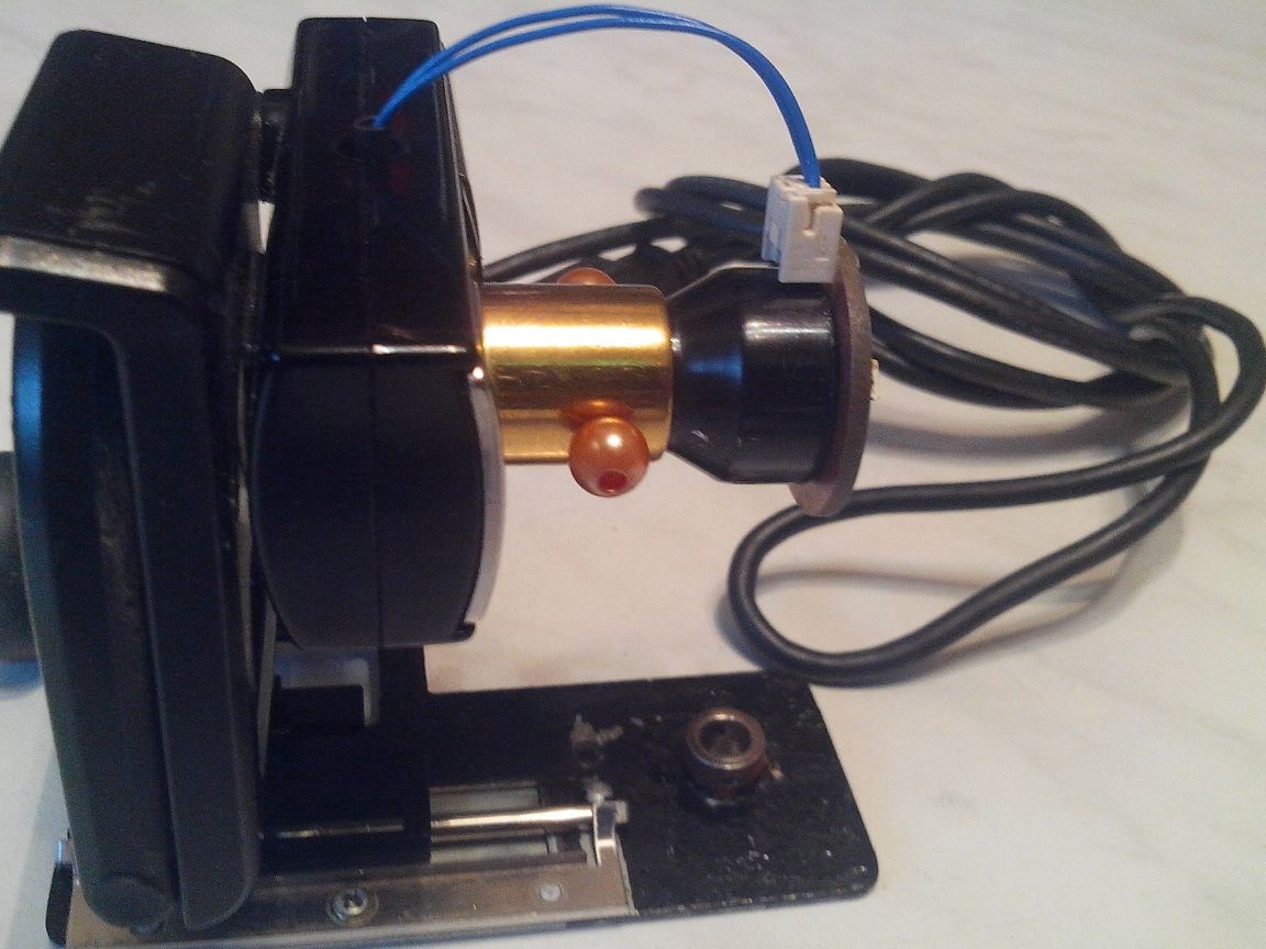
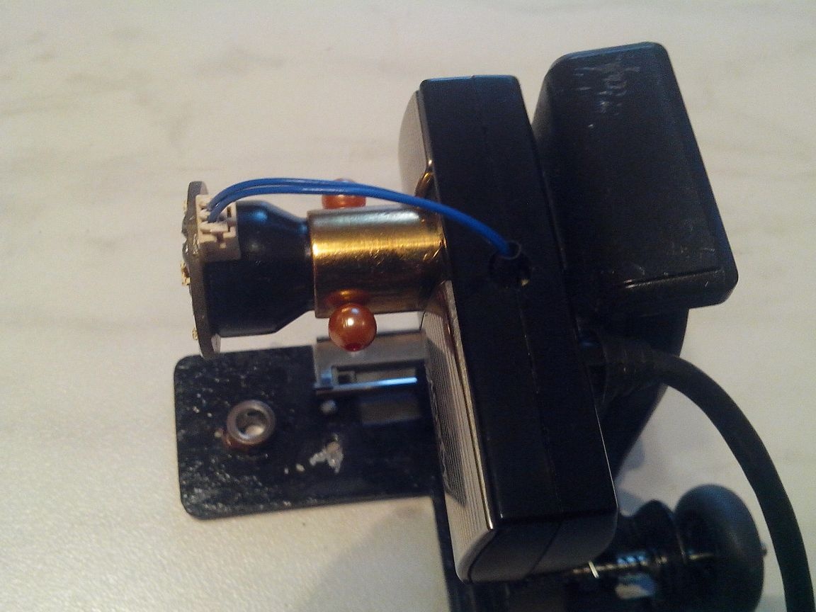
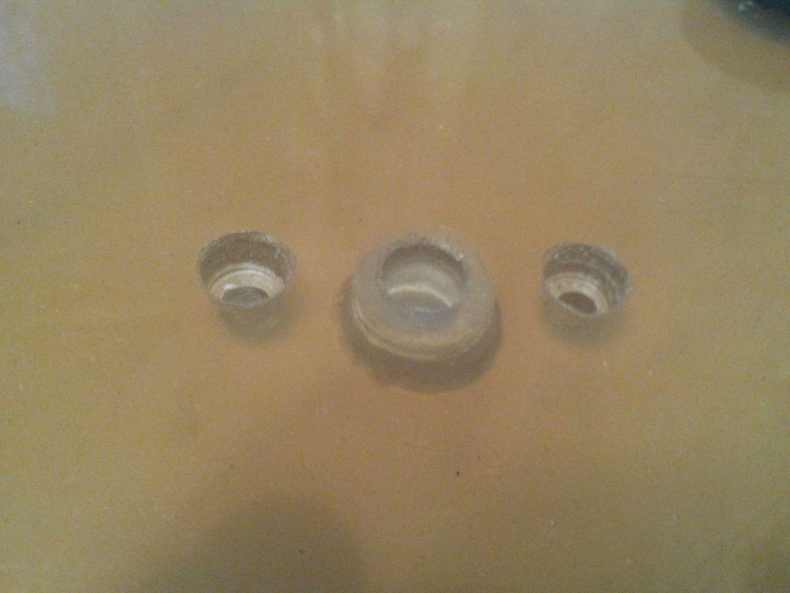
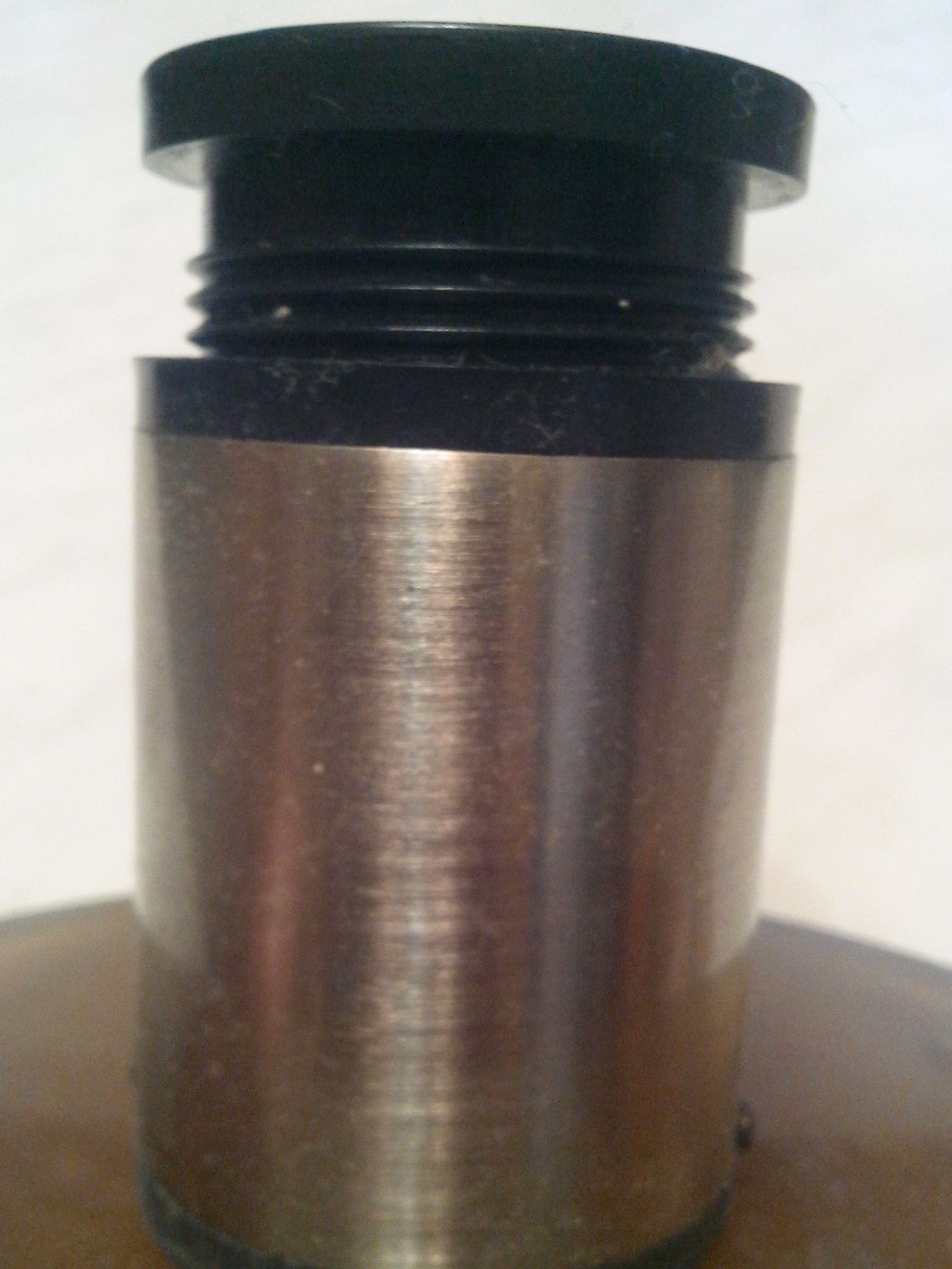
Further, having disassembled it, I carefully removed my native optics, leaving only the pixel matrix, and installed a bronze bushing in place of my native optics, which I turned on a lathe in the dimensions of the new optics.
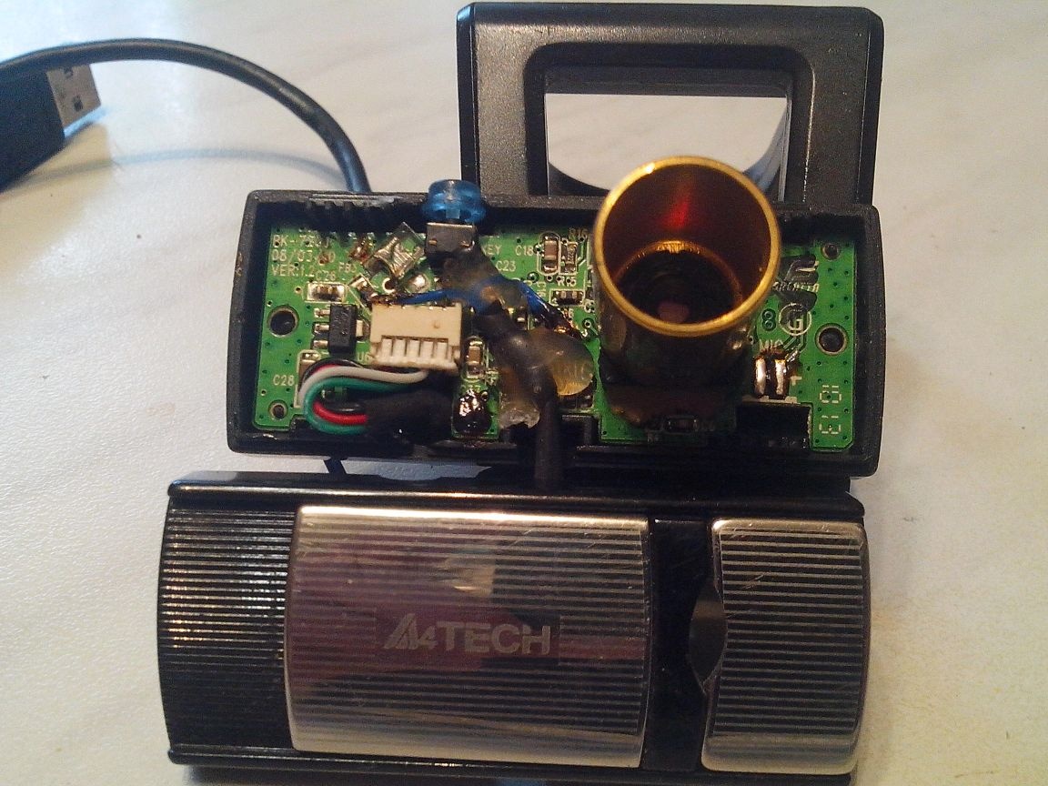
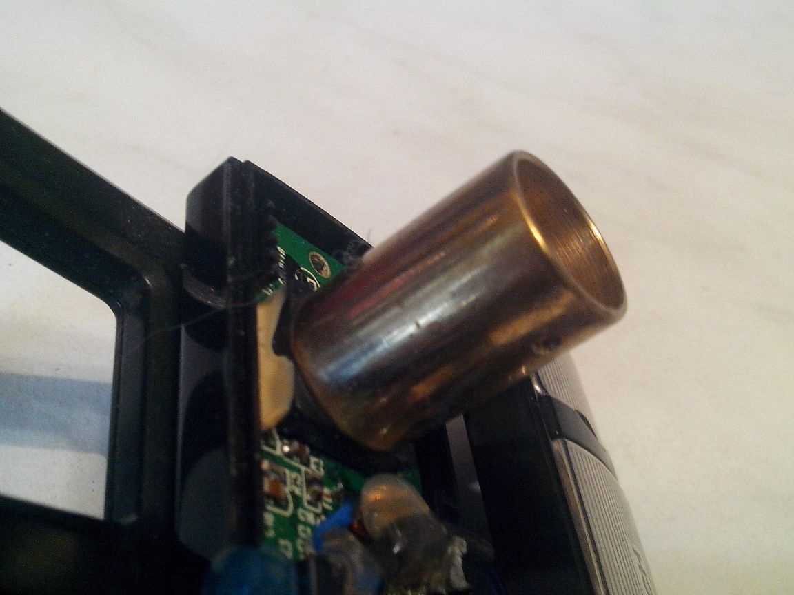
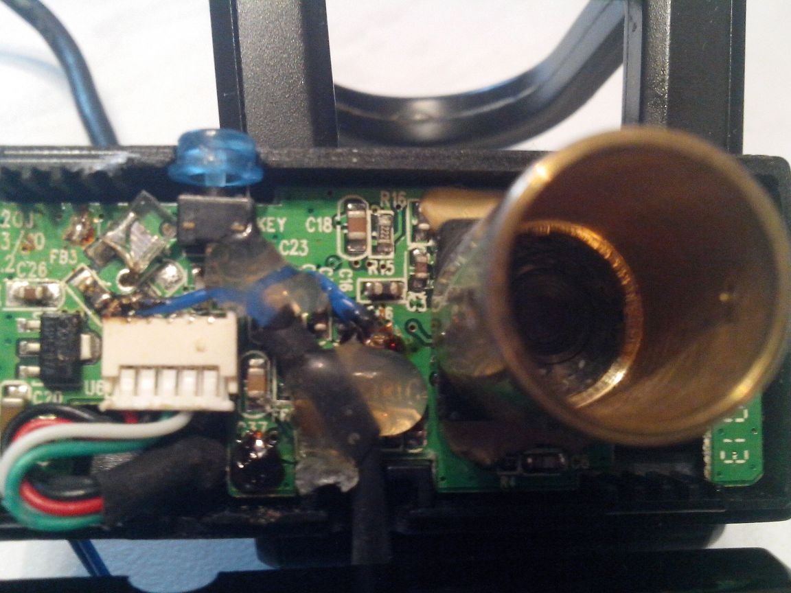
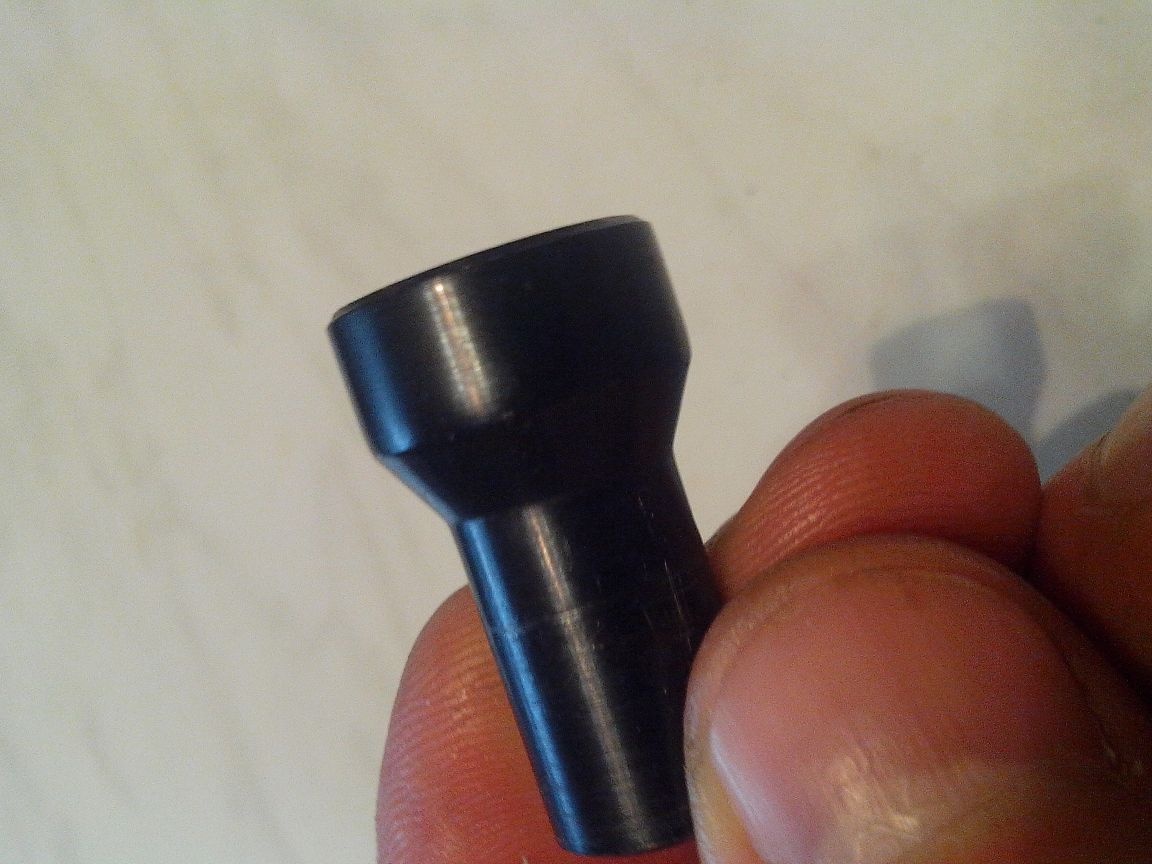
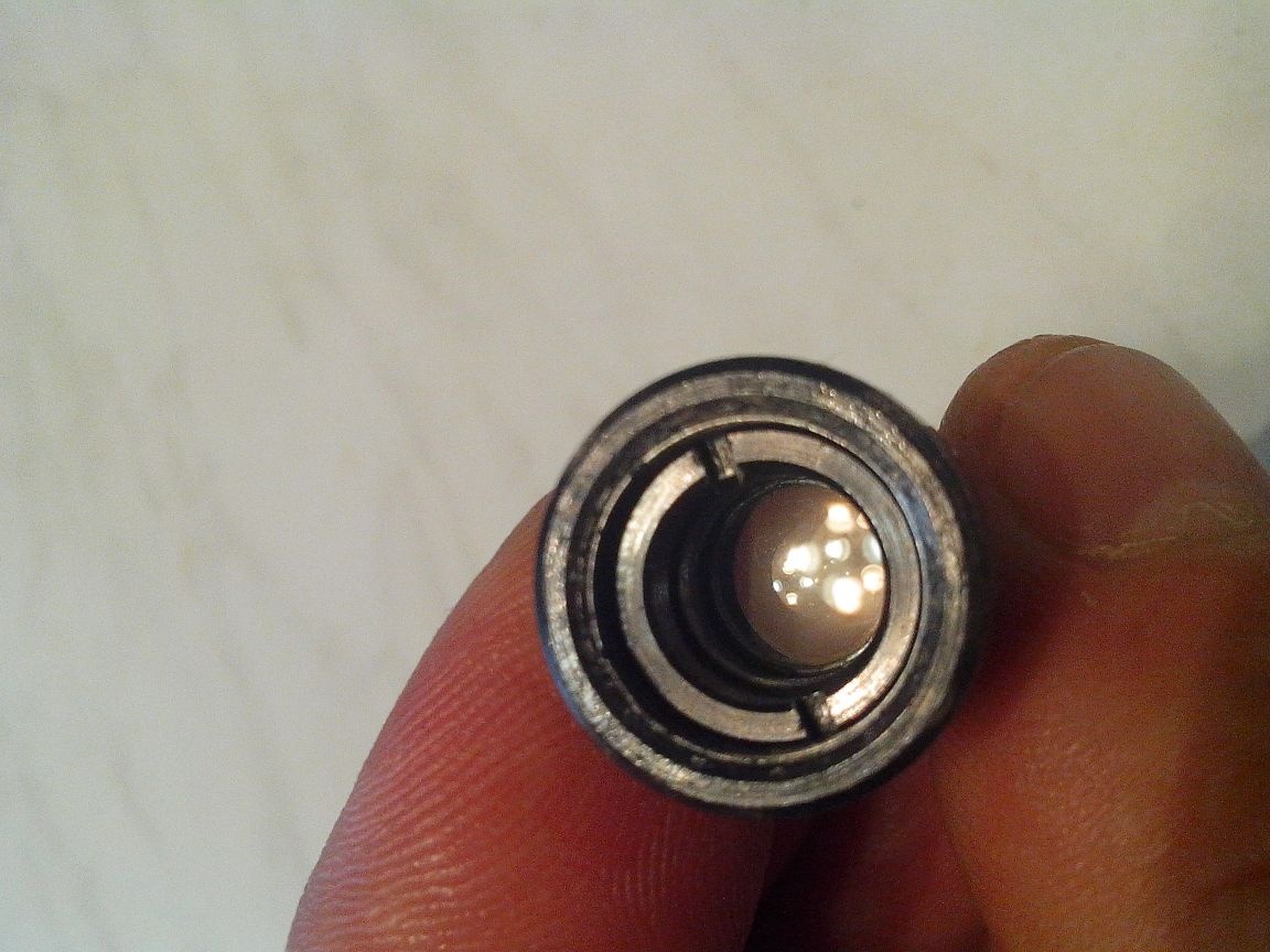
I took the new optics from some kind of children's optical sight.
To fix the optics in a bronze bushing, I drilled two holes ø 1.5 mm in it (bushing) and cut an M2 thread.
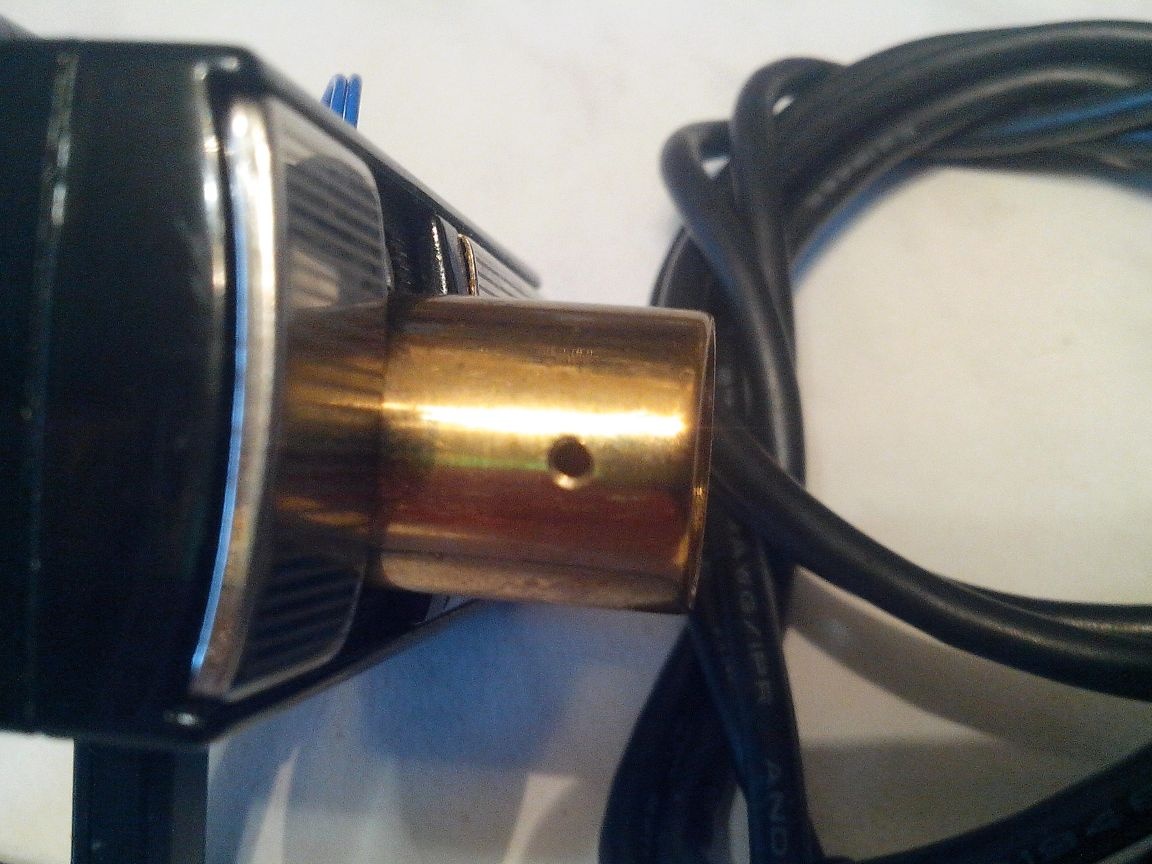
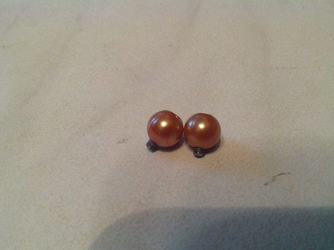
I screwed M2 bolts into the obtained threaded holes, on the ends of which I glued beads for convenience of unscrewing and twisting, in order to change the position of the optics relative to the pixel matrix in order to increase or decrease the focal length of my USB microscope.
Next, I thought about the backlight.
Of course, it was possible to make an LED backlight, for example, from a gas lighter with a flashlight that costs a penny, or from something else with self-powered, but I decided not to clutter the design and use the power of the webcam, which is fed via a USB cable from a computer .
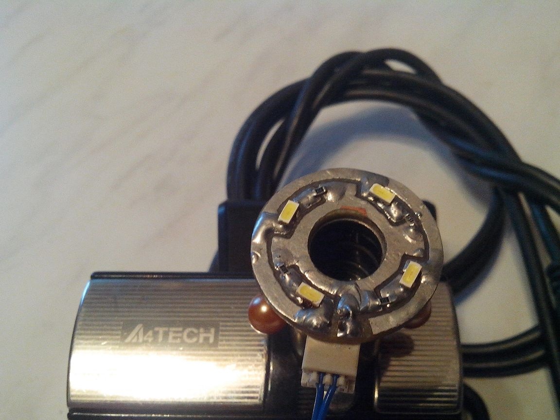
To power the future backlight, with the USB cable that connects the webcam to the computer, I brought out two wires with a mini-jack (male) - “+ 5v, from the red wire of the USB cable” and “-5v, from the black wire”.
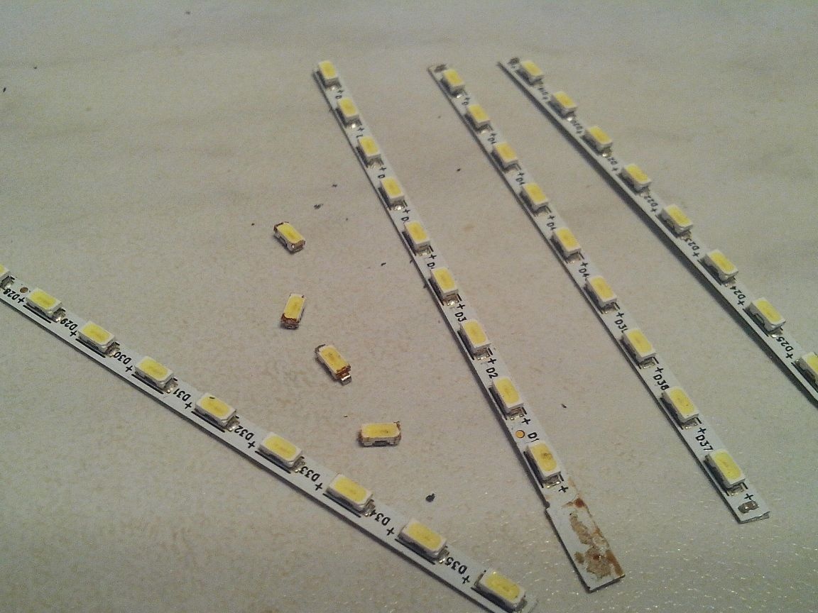
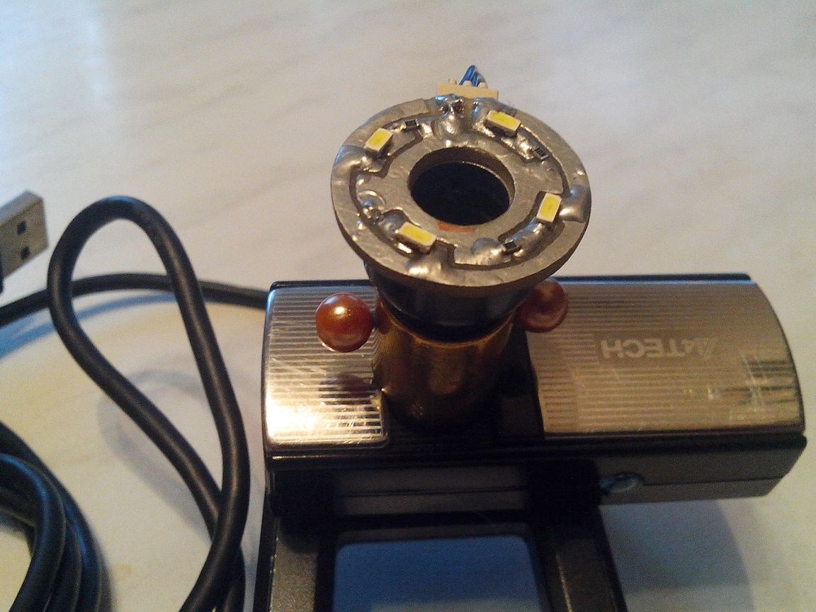
To minimize the design of the backlight, I decided to use LED-LEDs, which are pulled out of the LED backlight tape from the broken matrix of the laptop, fortunately, such a tape has long been in my pocket.
Using a pair of scissors, a suitable drill and a file, we made a ring of the required size from double-sided foil fiberglass and cut on one side the ring A of the track for soldering LED-LEDs and quenching SMD-resistors with a nominal value of 150 ohms (I put a resistor of 150 ohms in the gap of the positive power wire of each LED ) soldered our backlight. To connect power from the inside of the ring, I soldered a mini-connector (mother).
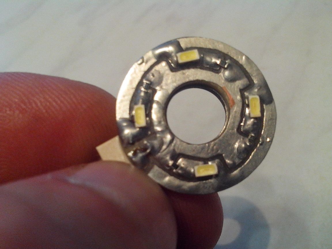
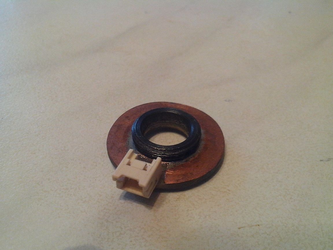
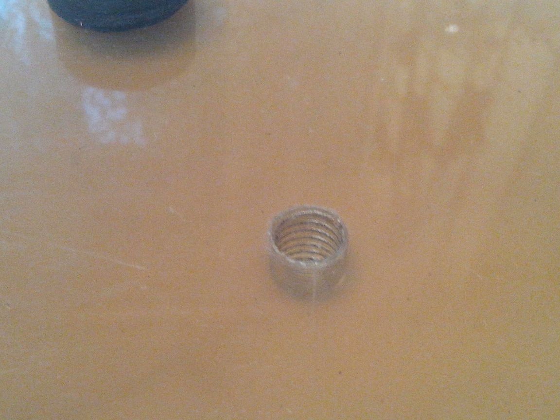
To connect the backlight to the lens, I used (not used for attaching the lens glasses) a round nut with a thread that was soldered to the inside of the backlight ring (which is why I took the double-sided fiberglass).
So, the electron-optical part of the USB microscope is ready.
Now you need to think about a movable mechanism for fine-tuning sharpness, a movable tripod, the base and the work table.
In general, it remains to come up with and create the mechanical part of our homemade product.
Go…
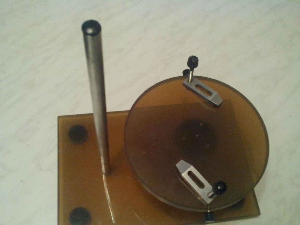
2. As a moving mechanism for fine-tuning sharpness, I decided to take an outdated mechanism for reading floppy disks (the people called it a “floppod”).
For those who have not found this “miracle of technology”, it looks like this:
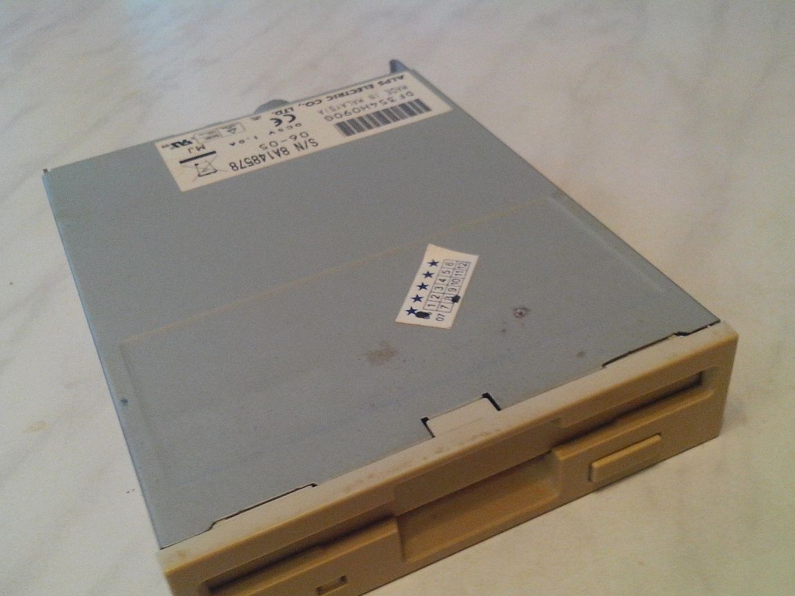
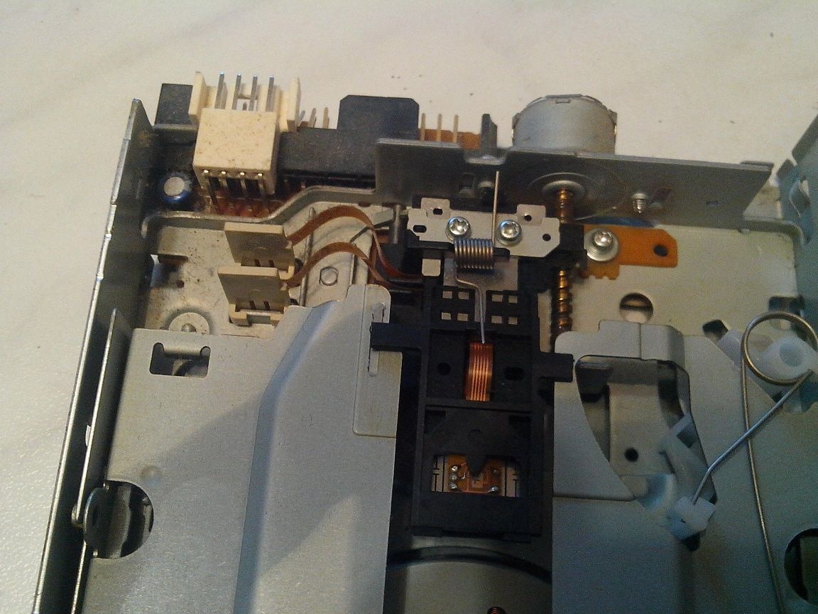
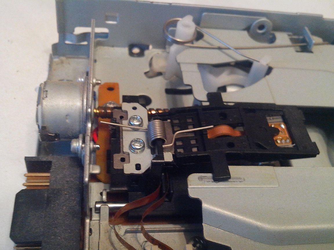
In short, after completely disassembling this mechanism, I took the part that was responsible for the movement of the read head, and, after mechanical refinement (cutting, sawing and file processing), this is what happened:
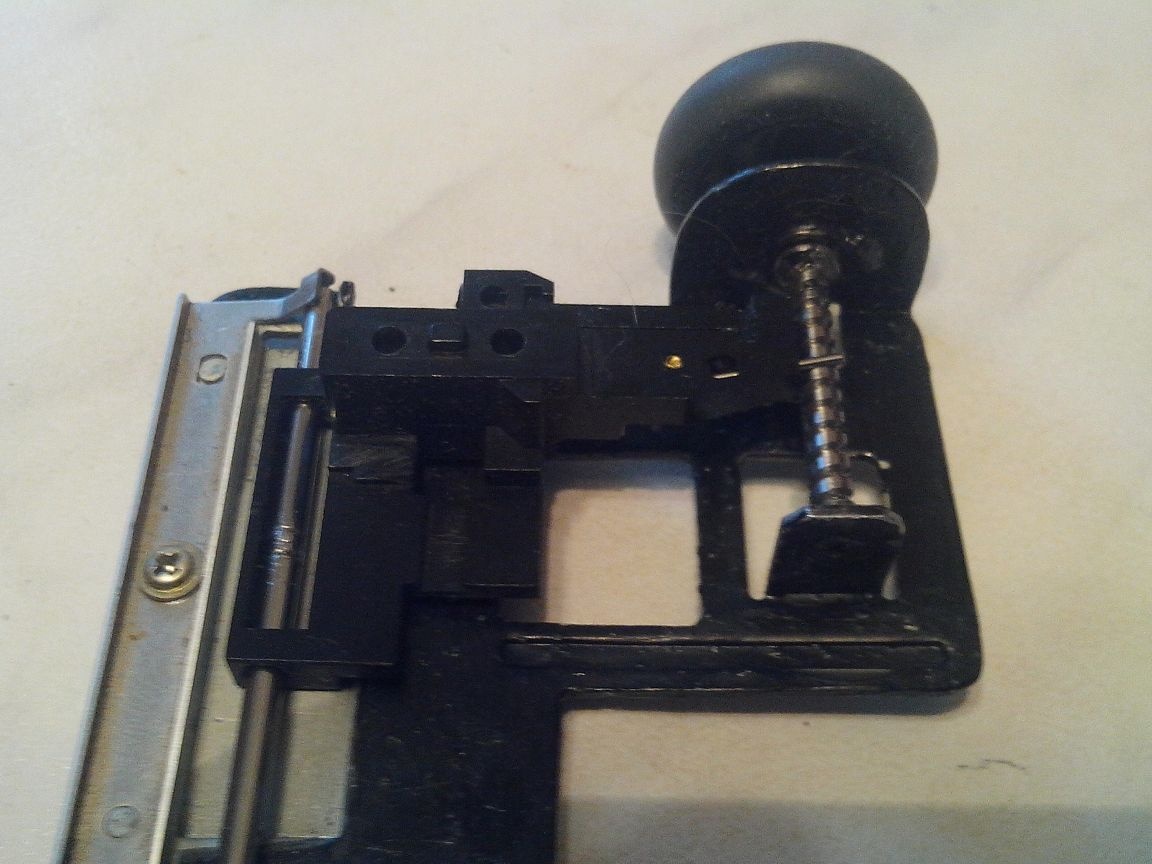
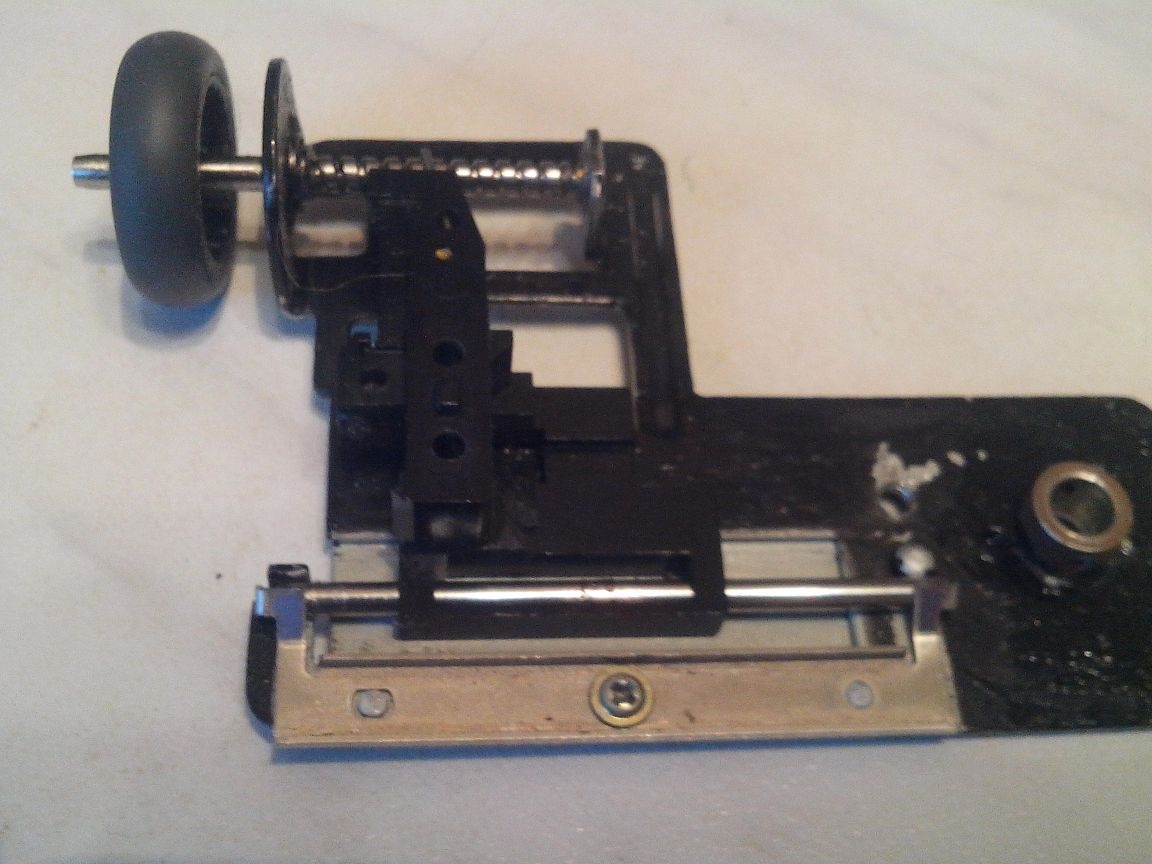
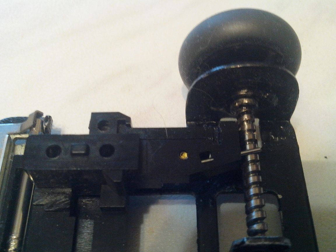
To move the head in the floppod, a micromotor was used, which I disassembled and took only the shaft from it, securing it back to the movable mechanism. For the convenience of rotating the shaft, on its end, which was inside the engine housing, I put on a roller from the scroller of an old computer mouse.
Everything turned out as I wanted, the movement of the mechanism was smooth and accurate (without backlashes). The movement of the mechanism was 17 mm, which is ideal for fine-tuning the sharpness of the microscope at any focal length of the optics.
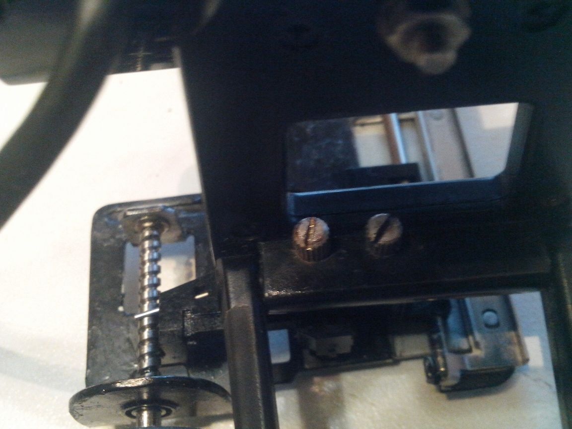
With the help of two M2 bolts, I fixed the electron-optical part of the USB microscope to a movable mechanism to fine-tune sharpness.
The creation of a mobile tripod did not cause any special difficulties for me.
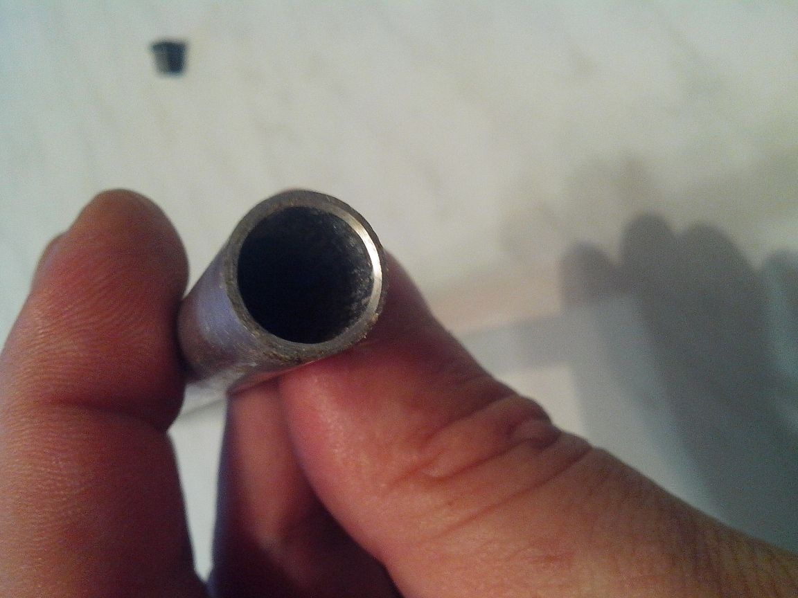
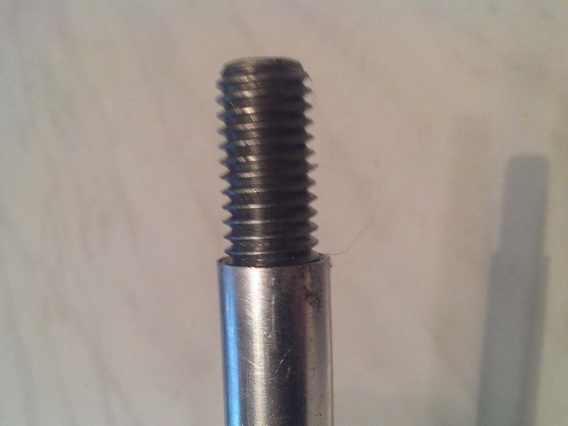
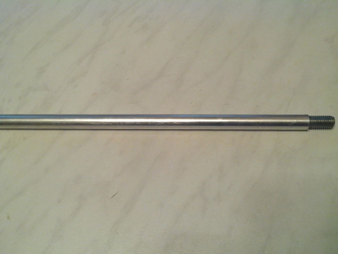
3. Since the days of the USSR, the UPA-63M magnifier was lying in my shed, the details of which I decided to use. For a tripod rack, I took just such a ready-made rod with a mount, which was included with the magnifier. This rod is made of an aluminum tube with an outer ø 12 mm and an inner ø 9.8 mm. To fix it to the base, I took the M10 bolt, screwed it to a depth of 20 mm (with effort) into the rod, and left the rest of the thread by cutting off the head of the bolt.
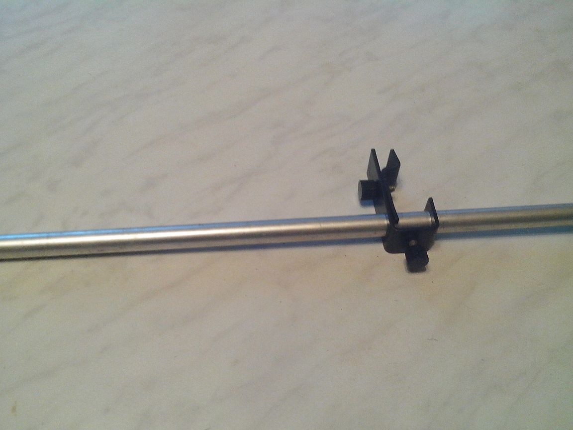
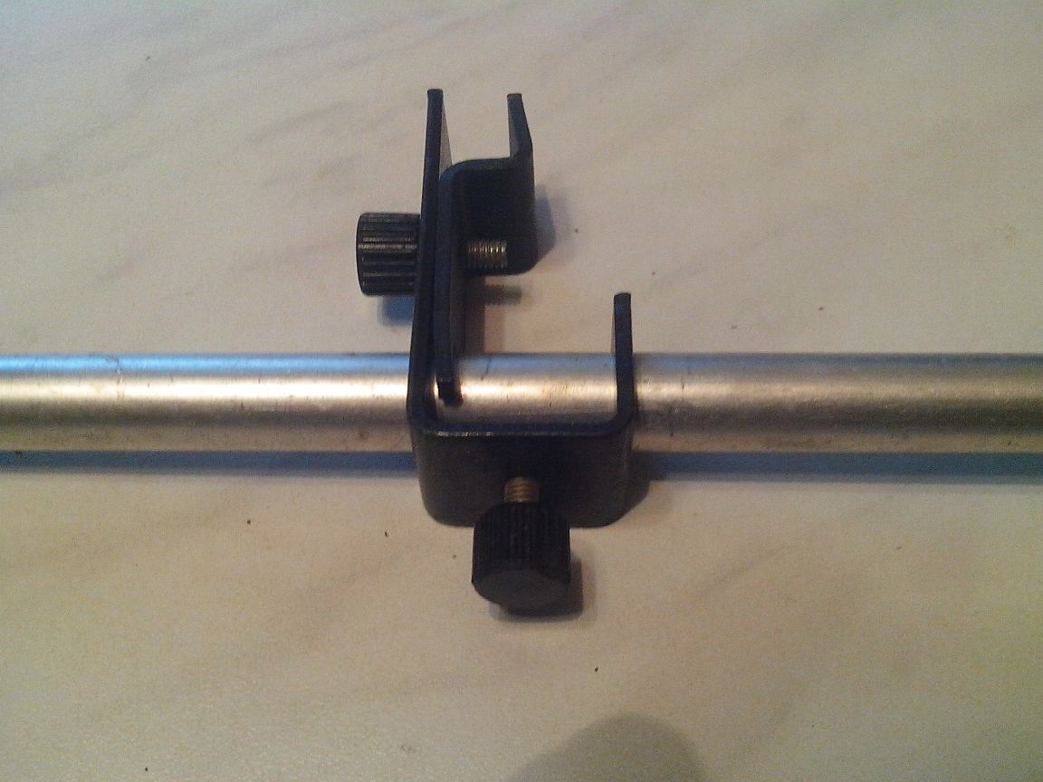
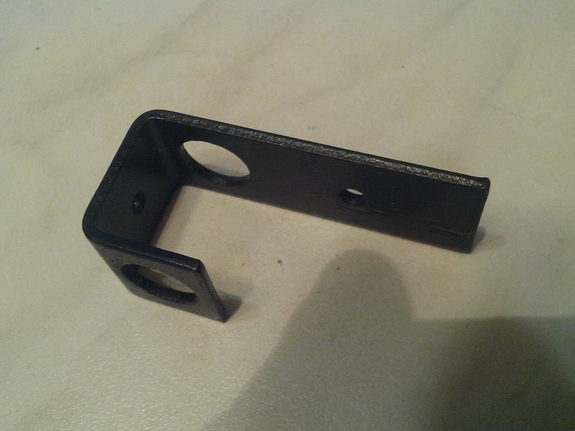
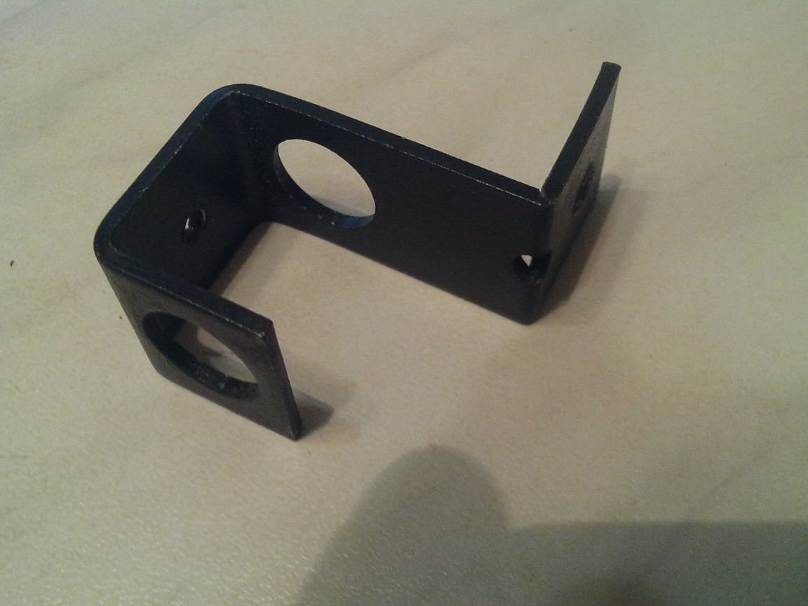
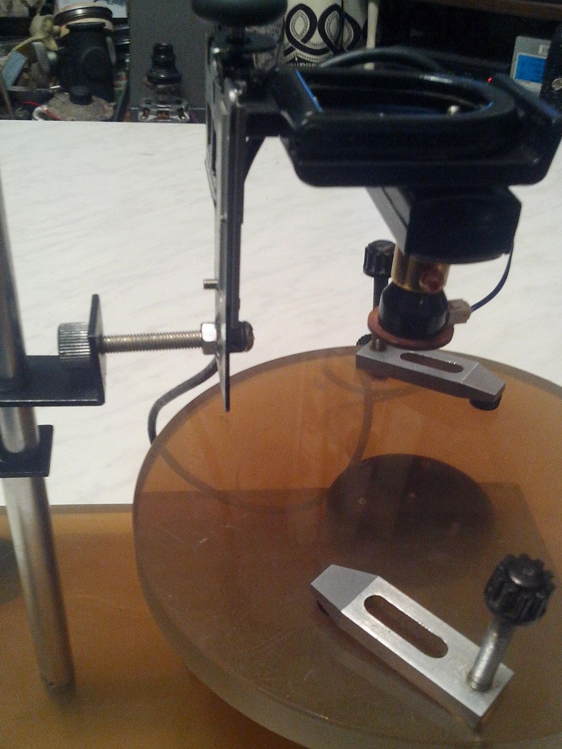
The mount had to be slightly modified to connect it with the microscope parts prepared in paragraph 2. To do this, I bent the end of the mount (pictured) at right angles and drilled a hole ø 5.0 mm in the bent part.
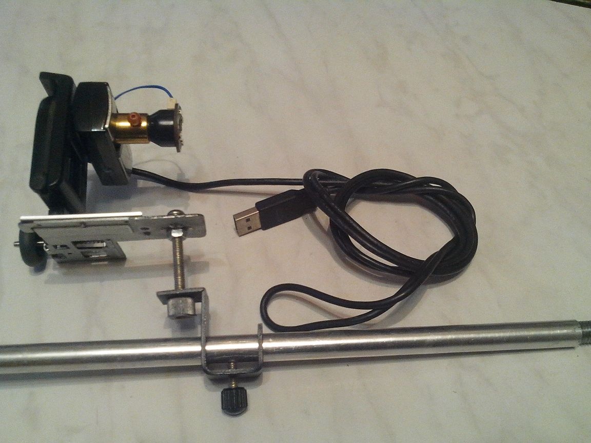
Then everything is simple - with a M5 bolt 45 mm long, connect the pre-assembled part with the fastener through the nuts and put it on the rack, securing it with the locking screw.
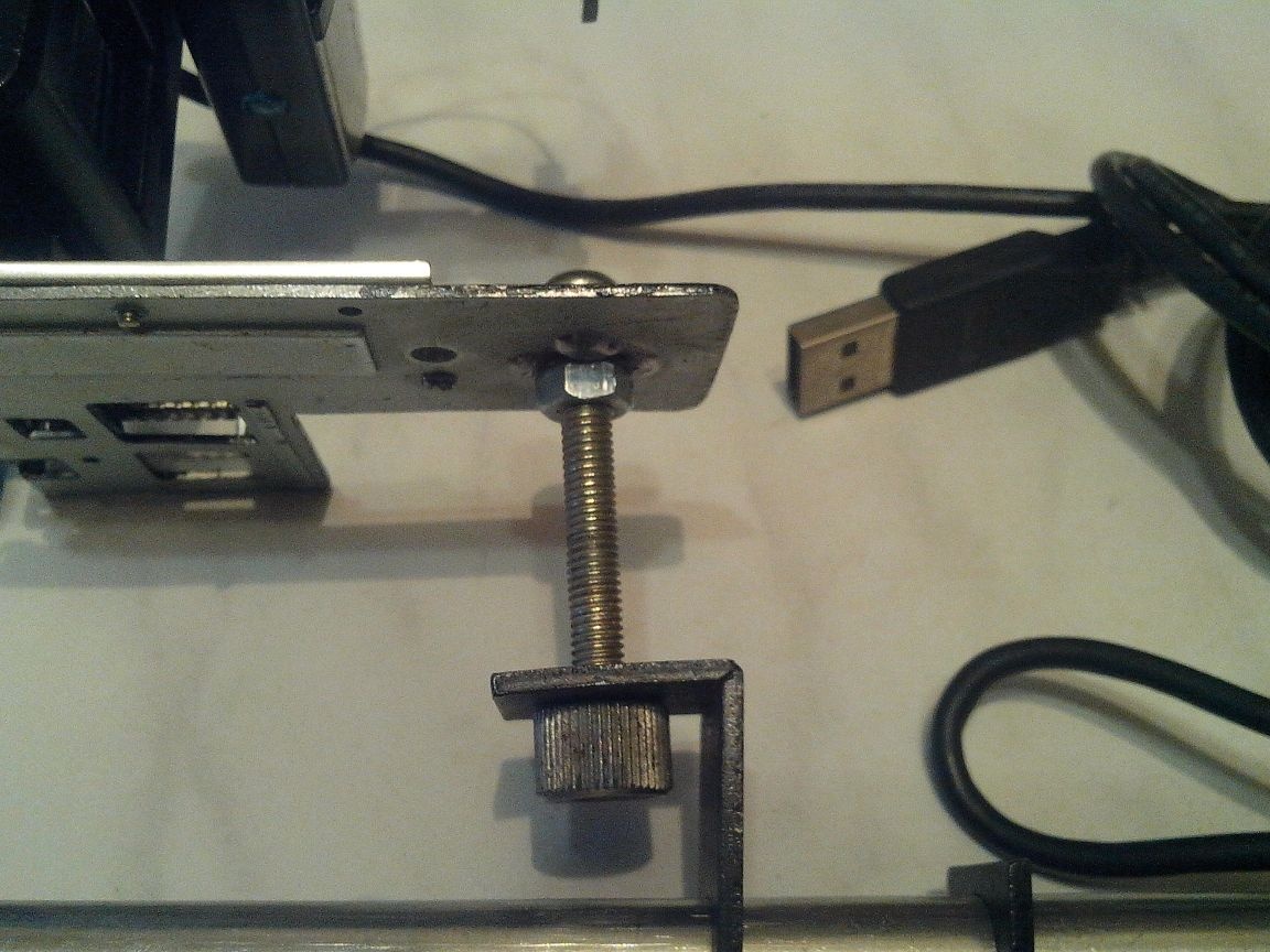
Now the base and the table.
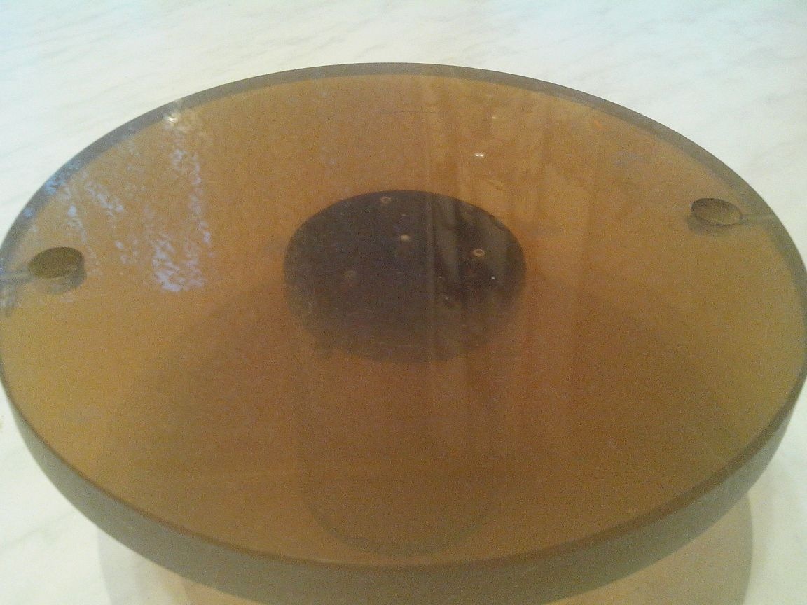
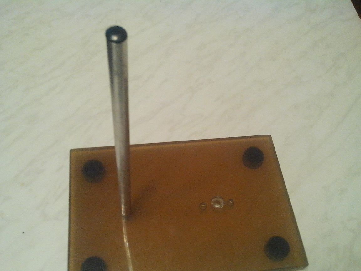
4. From ancient times, I had a piece of translucent plastic light brown in color. At first I thought it was plexiglass, but when processing it I realized that it wasn’t. Well, oh well - I decided to use it for the base and table of my USB microscope.
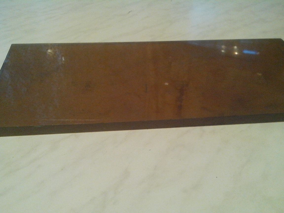
Based on the dimensions of the previously obtained design, and the desire to make a large table for reliable mounting of boards during soldering, I cut a 250x160 mm rectangle from the existing plastic, drilled a ø 8.5 mm hole in it and cut an M10 thread for attaching the rod, as well as the hole for fixing the base of the table.
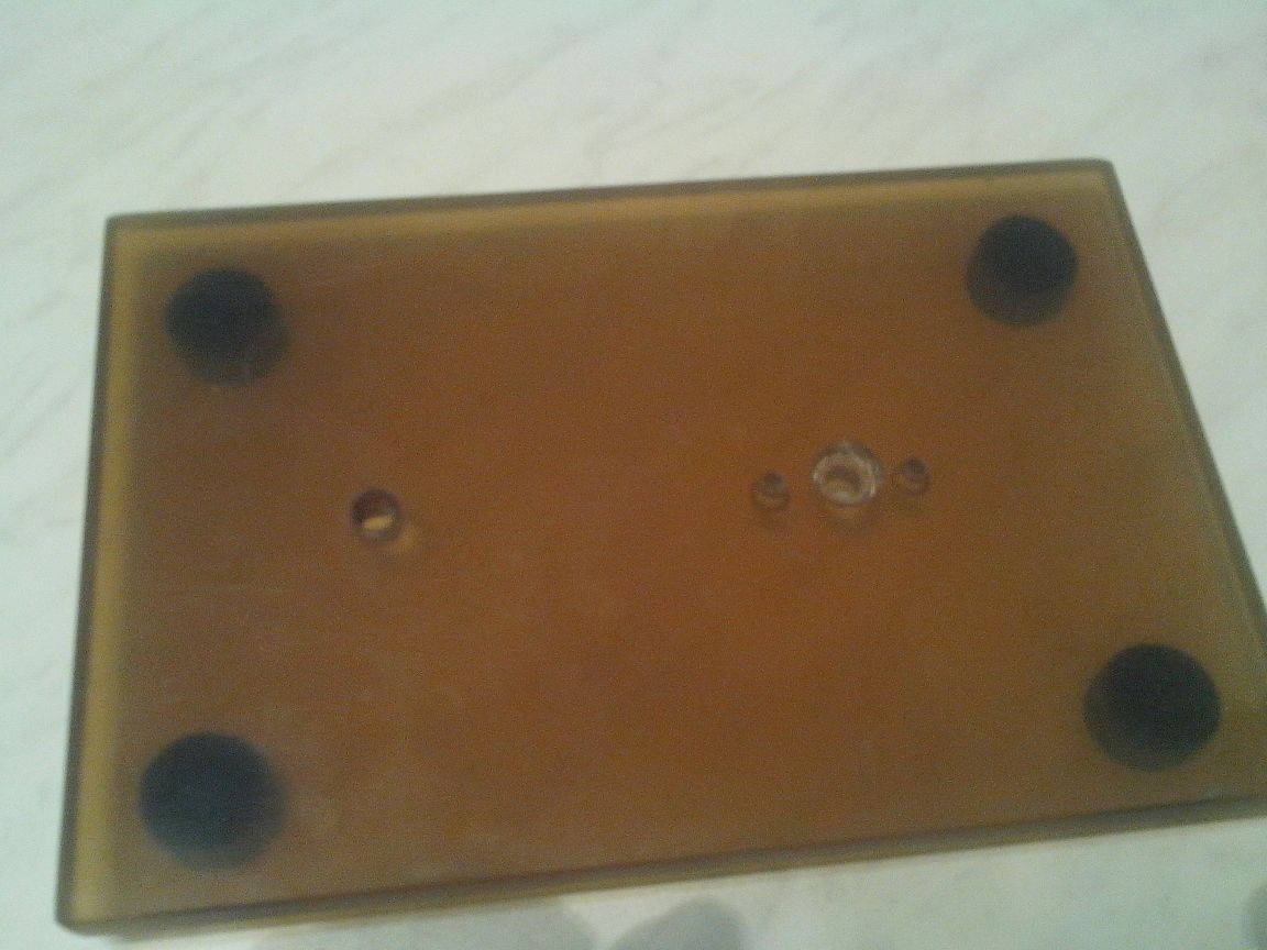
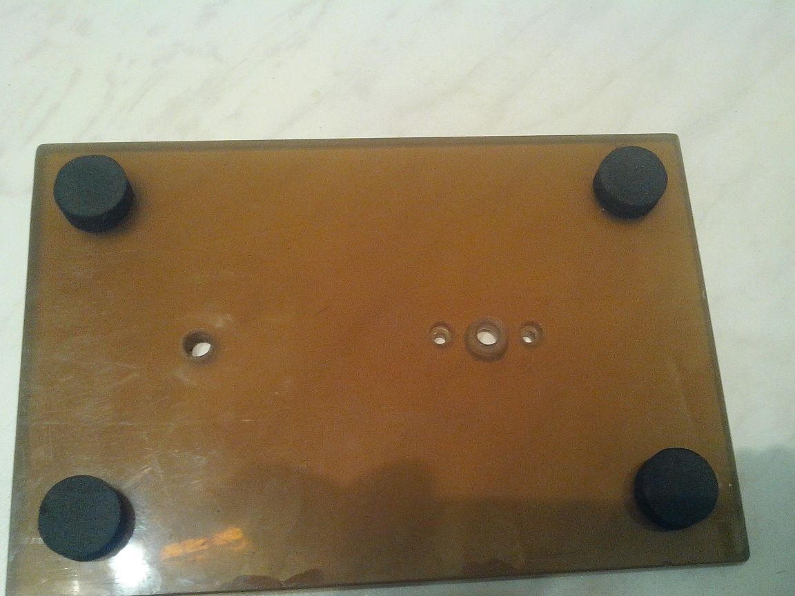
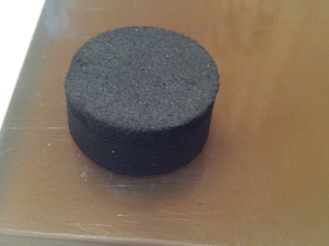
I glued legs to the bottom of the base, which I cut from the sole from old shoes with a homemade drill.
5. The table was machined on a lathe (in my former enterprise, of course I do not have a lathe, although there is a 5th digit of a lathe) of 160 mm in size.
As the basis for the table I took a stand for alignment of furniture relative to the floor, it fit perfectly in size and looks presentable, besides, it was given to me by a friend who has this furniture, "like a fool shag."
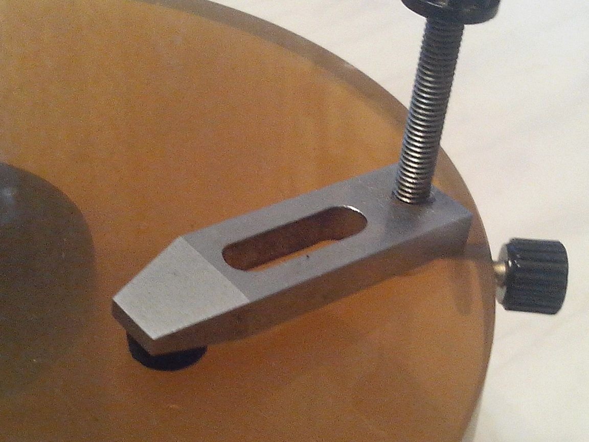
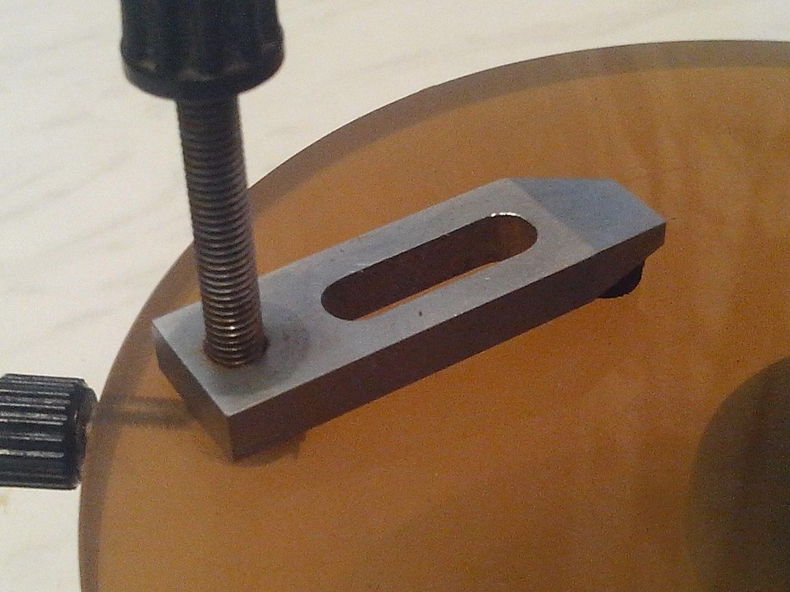
On the top of the table, I attached paws to fix the boards that have been in the bins since ancient times, I don’t even know what they came from and where I came from. Due to the fact that the table is rotary, even large-sized boards for repair can be placed on it.
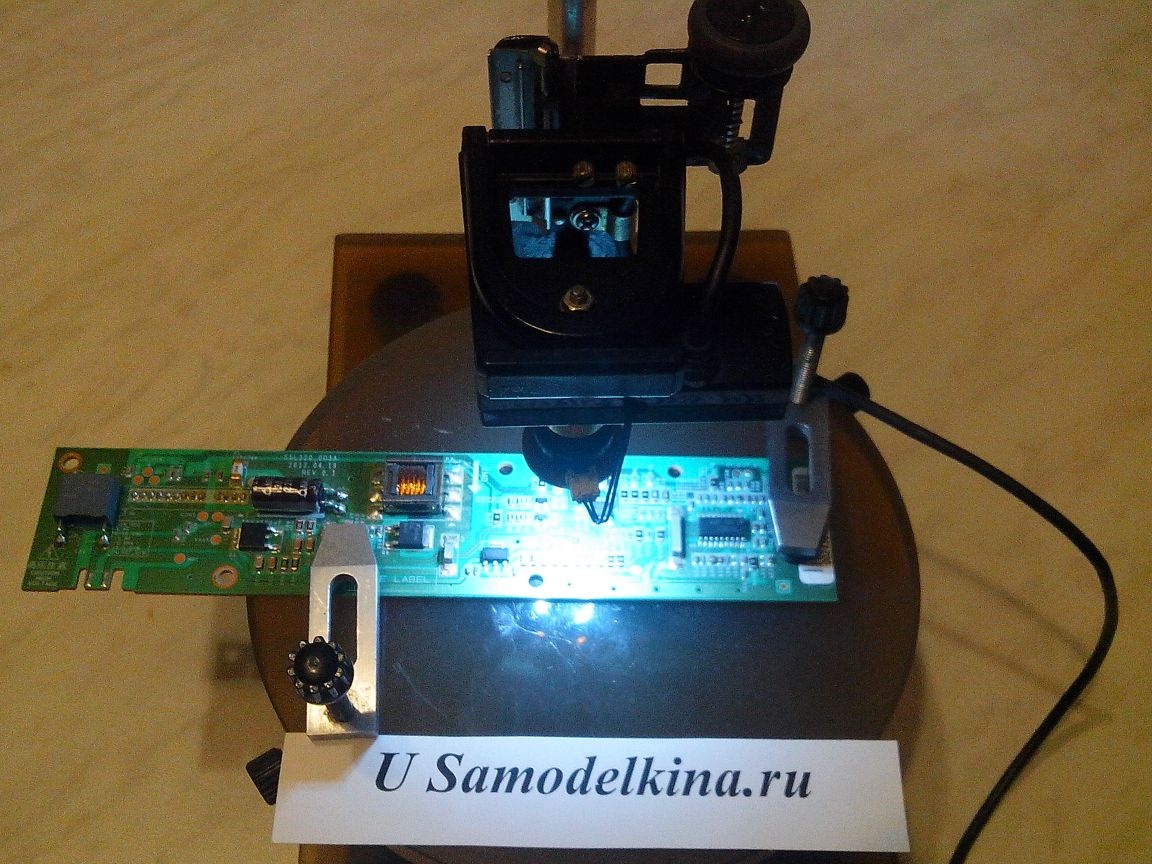
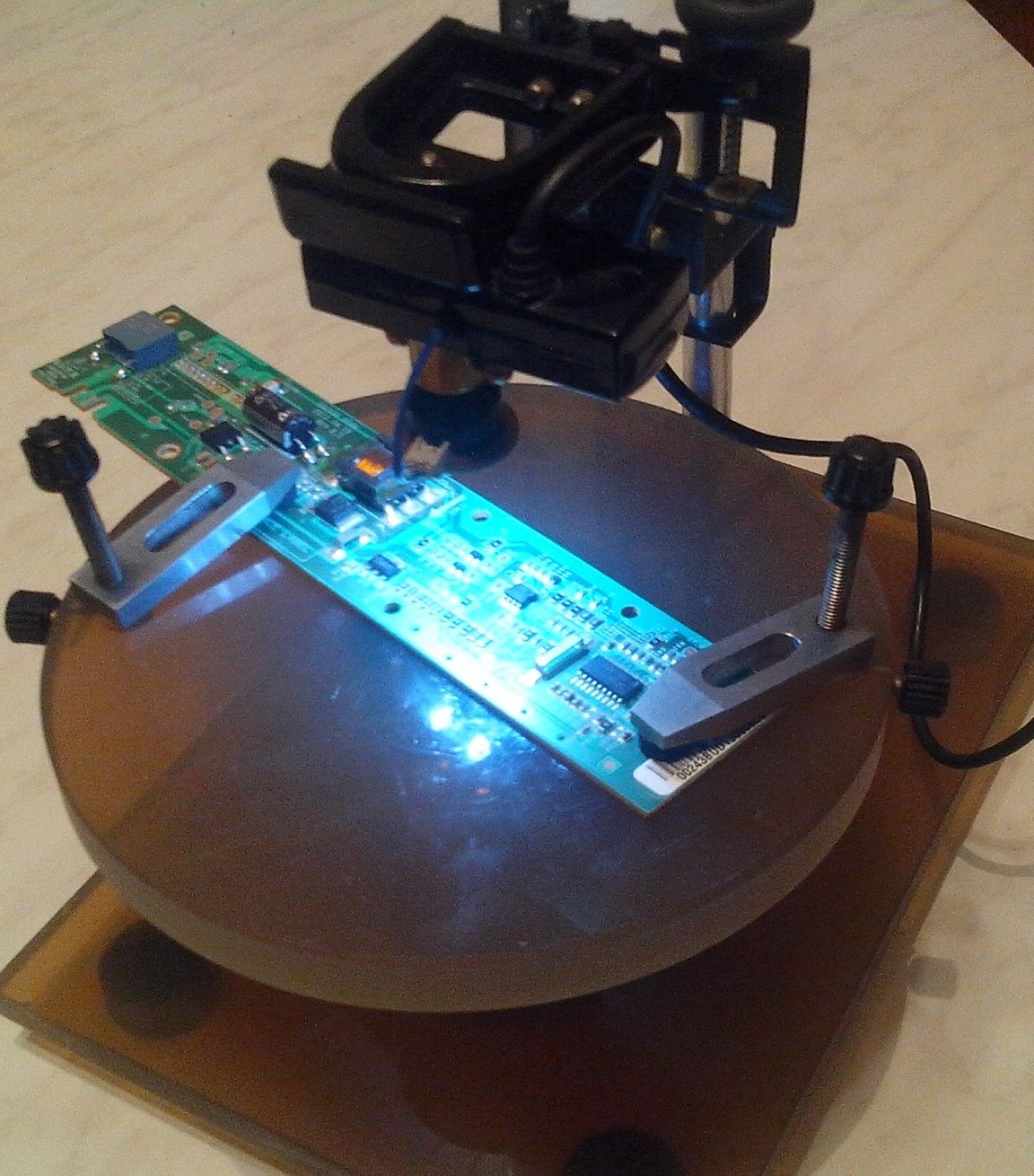
Well, that’s all, we assemble our USB microscope into a single design and connect it to a computer. We see the result:
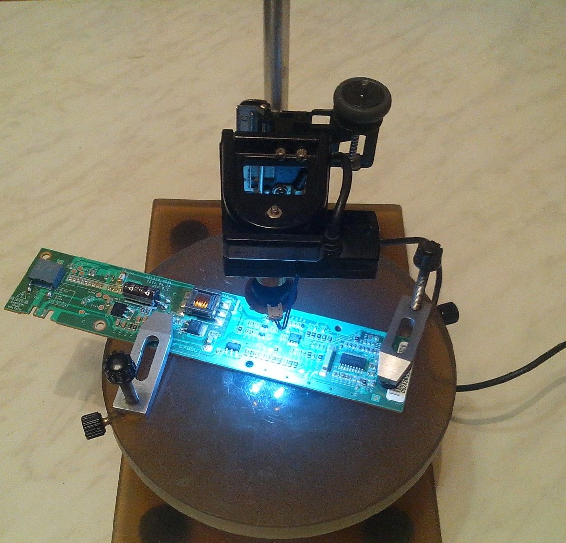
For a larger and better display of the video from the microscope, I turn it on through Daum Potplayer and put the picture on the TV.
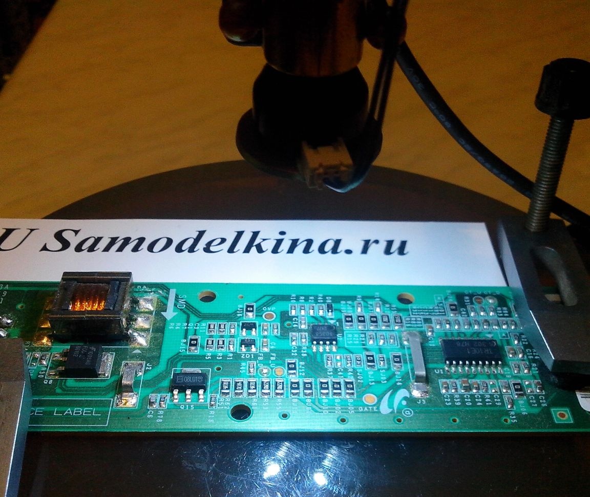
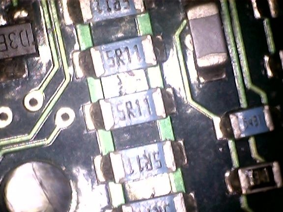
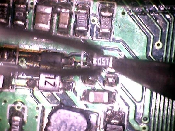
Here are the images via Daum Potplayer on the monitor:

For those who do not know how to open a webcam through Daum Potplayer I explain:
1. Right-click on the screen of the open Daum Potplayera.
2. In the window that appears, move the cursor to the second line at the top of “Open”.
3. Go to the second window that opens.
4. Click on the ninth line from the top “Open webcam”
All we get is a full-screen image.
If necessary, display the peripheral device.
P.S. The focal length of my USB microscope is about 70 mm.
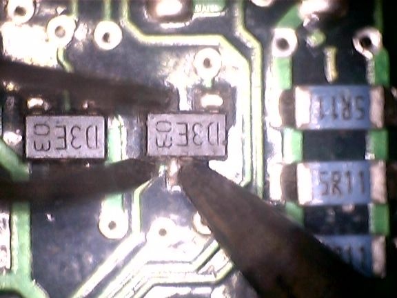
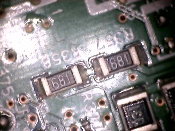
This is enough to easily get the parts with a soldering iron and tweezers for the purpose of dismantling and installation, and the increase is quite acceptable, which is clearly visible in the last two frames.
Thank you for your interest in my design.
I wish you all good luck and creative success.
Regards, MNS1961.