» Electronics »Contactless key

Contactless key

Contactless key

This article will talk about one of the simplest manufacturing schemes of some kind of contactless key circuit. In essence, this will be a device that consists of a transmitter operating by supplying the battery and a receiver for this transmitter, which can be installed in any device. The meaning of the operation of such a device is as follows: the device into which the receiver is inserted begins to work only when the transmitter is approaching.

The operating range of the assembled proximity key device is approximately 5 cm.

Materials:
transistor KT940
1.5V battery
- round frame with a diameter of 5 cm
- copper wire 0.1-0.6 mm
-relay

Description of the operation and creation of the device:

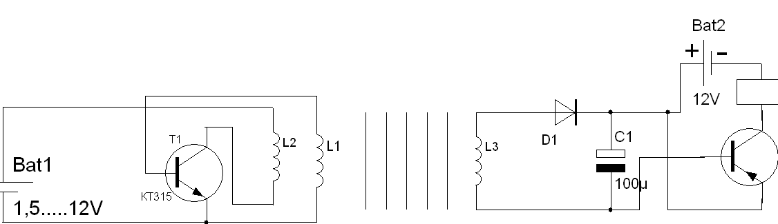
Below is a diagram of this device:


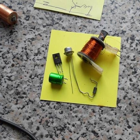
To begin with, all the necessary details and elements were collected to create this device.


The transmitter in this device is a standard high-frequency generator, and a blocking generator will serve as its basis. The author used the KT940 transistor in his circuit, although it is indicated that other npn transistors of the 3, 6, 9 series are suitable, since they are basically generator ones.

In fact, a 1.5V battery will suffice for the operation of the transmitter circuit, but if you install a battery with a higher voltage, the range at which the key device will operate will be higher.

One of the obvious disadvantages when using such a device circuit is the fact that to start the transmitter, it is necessary to short-circuit the base and collector. In principle, a similar flaw can be solved by installing the start button.

The receiver for this device works as follows: when the L3 coil enters into resonance with the transmitter, an alternating current is induced in it, which is rectified and opens the transistor T2 (MP20OS). Then, approximately according to the same principle, relay K1 is activated. The main device is subsequently connected to this relay, which is modified by a contactless key system.

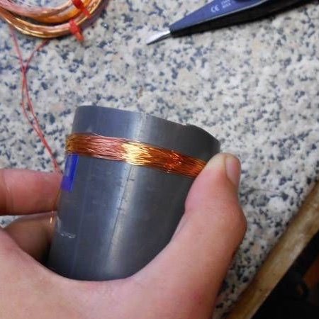
To create a transmitter, the first thing you need to do is reel a coil. A round frame with a diameter of about 5 cm and a wire were used to wind the reel. The author advises using a wire from 0.1 mm to 0.6 mm, given that the thicker the wire, the greater the current consumption. The number of turns for coils L1 and L3 is 60, and for coil L2 is 30 turns.

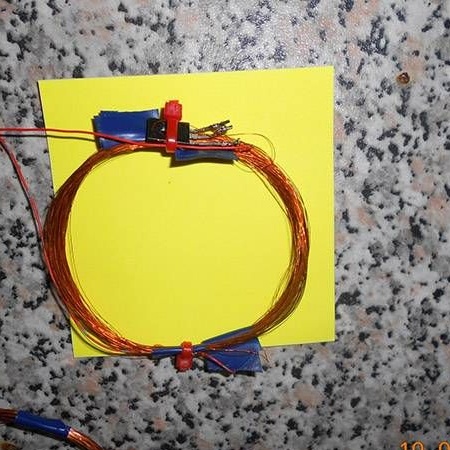
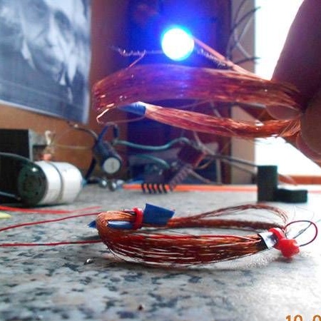
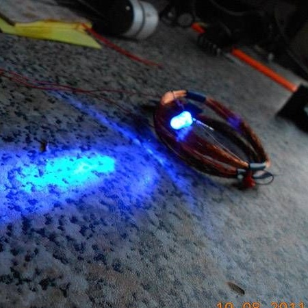
After this, the windings are soldered with a transistor according to the above diagram and stacked one on top of the other. Thus, a rather interesting installation is obtained: when the LED is connected directly to the outputs to the L3 coil, an effect is obtained that can be called a kind of wireless power transmission.

Actually, in the same way you can check the operation of the device. If the device does not work, it is necessary to close and open the base and the collector, or turn over one of the windings of the transmitter.

Tests have shown that the field passes through 338 layers of glossy paper, which means that there will be no problems with the operation of the device when it is installed in the case. The main thing to remember is that the case should not be metal.

By adding a relay and electronics to this scheme, it will be possible to find a huge number of applications for such a device, it can be either various entertainments with LEDs, or improvement of devices, devices or even a car to increase the guarantee of security against theft.

Below is a video showing the operation of the receiver and transmitter:
10
10
10

Add a comment

    • smilesmilesxaxaokdontknowyahoonea
      bossscratchfoolyesyes-yesaggressivesecret
      sorrydancedance2dance3pardonhelpdrinks
      stopfriendsgoodgoodgoodwhistleswoontongue
      smokeclappingcraydeclarederisivedon-t_mentiondownload
      heatirefullaugh1mdameetingmoskingnegative
      not_ipopcornpunishreadscarescaressearch
      tauntthank_youthisto_clueumnikacuteagree
      badbeeeblack_eyeblum3blushboastboredom
      censoredpleasantrysecret2threatenvictoryyusun_bespectacled
      shokrespektlolprevedwelcomekrutoyya_za
      ya_dobryihelperne_huliganne_othodifludbanclose
12 comments
KT940 is suitable, but in such a case there are a lot of 600s and 900s transistors.
And if you try with a hammer? : kissing:
And KT940 is suitable for this scheme? It seems the TO-126 (KT-27) case is as in the photo. Maybe the author made a mistake writing KT930 instead of KT940?
admin,
Is the circuit working?
As you well understand, this is just a model confirming the existence of electromagnetic waves. Transistors work in,, not optimal modes. And if the KT930 were really used in the generator, and not the transistor shown in the photo, then it would have been very likely to fail: powerful microwave transistors are extremely sensitive to the mode setting, sometimes it is necessary to use a temporary installation instead of such a transistor (especially if it works in heavy mode in the output stage) of its RLC equivalent, debugging the mode by direct current in the range of possible supply voltages and only then sealing it instead of the transistor equivalent.
And you read the article carefully:
The author used the KT930 transistor in his circuit

This is not enough to understand which transistor is used?

Of course, it’s not enough: in the text is KT930, in the diagram is KT315, in the photo there is a transistor in the TO-126 package, that is, not KT930, and not KT315.
It is necessary to show and teach by example - lay out your electronic home-made products, describe everything correctly - break the circle of world entropy!
And you read the article carefully:
The author used the KT930 transistor in his circuit

This is not enough to understand which transistor is used?
But you don’t find it to be strange: a person who thoughtlessly rewrote someone else’s absurdity receives a certain reward, and then another person tidies everything up for free?

Want to be an editor?
The source code is extremely carelessly written by a person who has very vague knowledge about electronics.

Is the circuit working?
did not ask leading questions

This way I try to somehow push the authors and "authors" to study an exciting and useful science - electronics.
The copyist accurately conveyed the meaning of the original article, what are the claims to it?

There is only one claim: why increase global entropy by disseminating false information?
Read carefully:
in generatorcalled "block generator"?
, not a transistor.
If you understand well in electronics, then it’s better to help make the articles more accurate - write what exactly is what to replace,

But you don’t find it to be strange: a person who thoughtlessly rewrote someone else’s absurdity receives a certain reward, and then another person tidies everything up for free?
This article, in general, cannot be brought to a worthy appearance, since this is not homemade work, but a model for conducting physical experience that does not have practical application. The source code is extremely carelessly written by a person who has very vague knowledge about electronics.
Replaced by a "blocking generator", right? In the article, the transistor is not called a “blocking generator”, but the transmitter circuit itself.

If you understand well in electronics, then it’s better to help make the articles more accurate - write what exactly to replace, rather than ask leading questions - there is no author of this scheme here - there is no one to answer your questions.

The copyist accurately conveyed the meaning of the original article, what are the claims to it?
And yet, what transistor is used in the generator, called the "block generator"?

We advise you to read:

Hand it for the smartphone ...