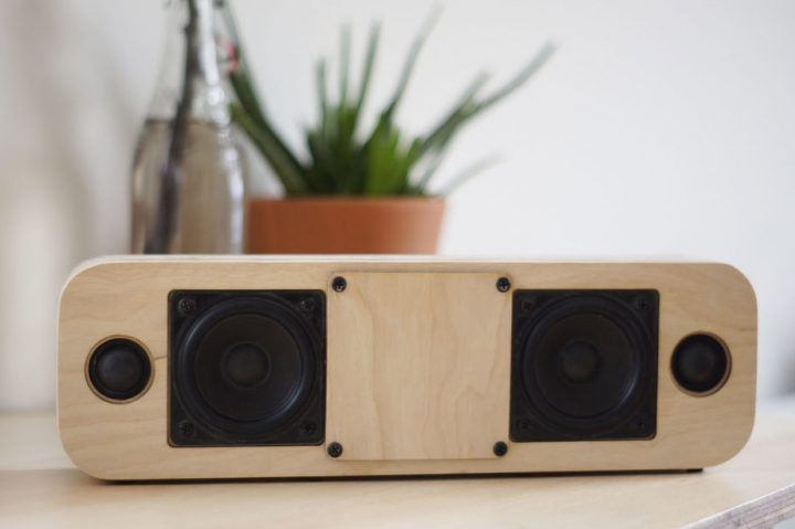
An interesting option for Bluetooth speakers with a power of 40 watts. The speaker is equipped with two low-frequency speakers, passive membranes, Bluetooth 4.0 with smart options. It is portable and powered by a lithium-ion battery. The outer casing is made entirely of plywood.
Materials:
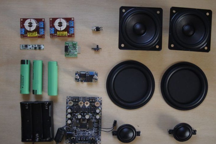
Amplifiers Yamaha 20W 2 pcs.
Bluetooth 4.0 module that has a battery indicator and a grounding insulator
3 lithium-ion batteries with protection circuit and quick charge
-20W low-frequency speakers and passive membranes
- two dual channel crossover
-protection board
-Charger
boost converter
- power connector and switch
plywood 18 and 3 mm thick
wood glue
Detailed description of creating a Bluetooth speaker:
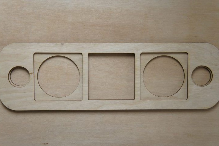
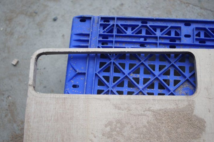
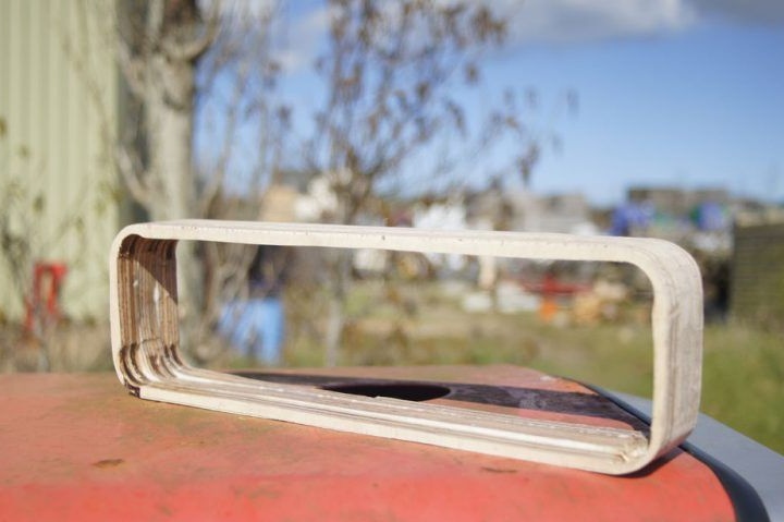
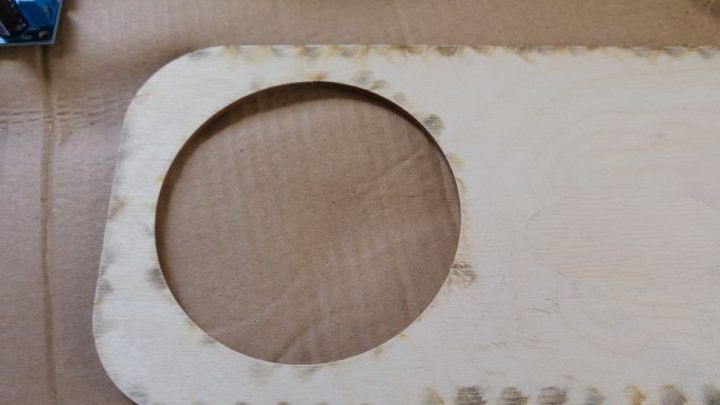
Step One: Designing Panels
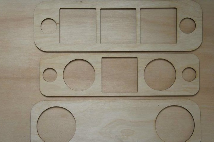
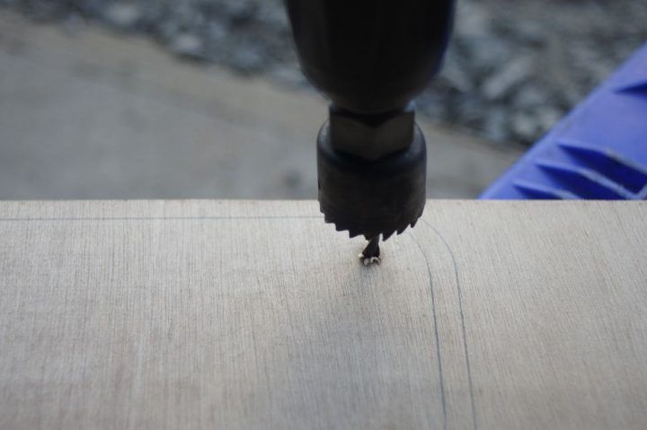
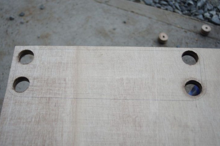
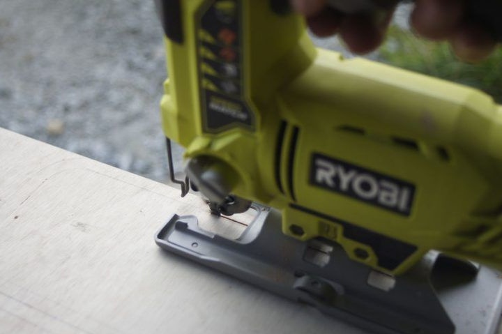
The panels were cut out of a 3 mm thick plywood sheet using a laser cutter. The same cutter made all the necessary holes for speakers, switches, etc.
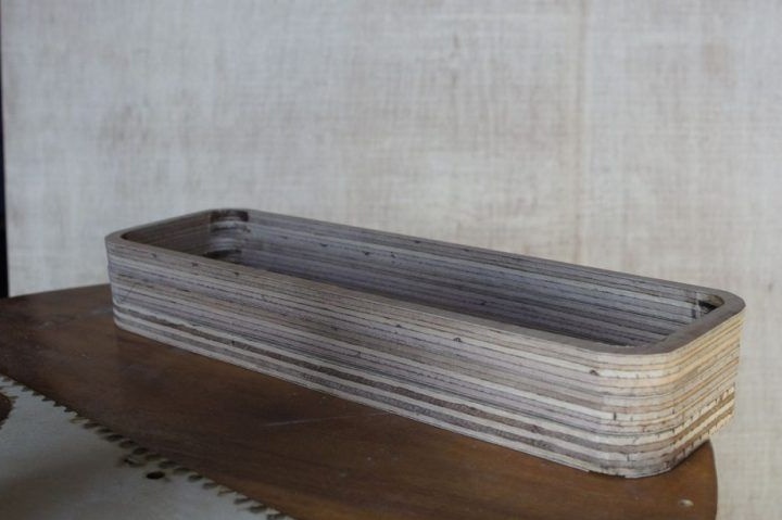
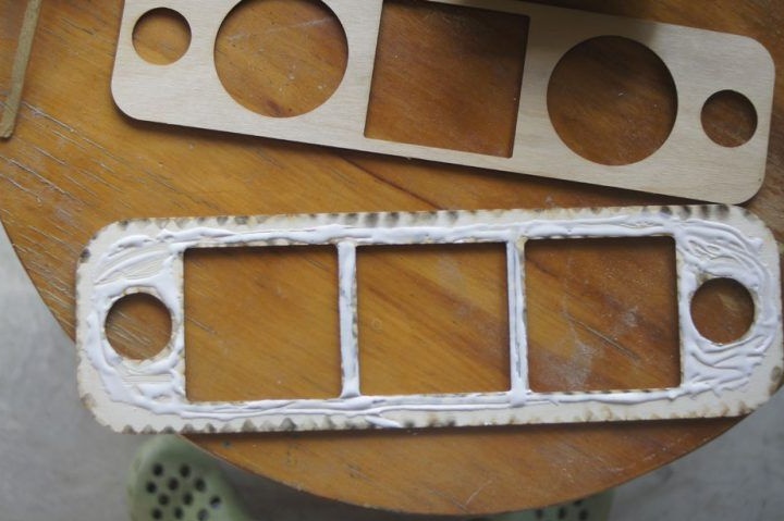
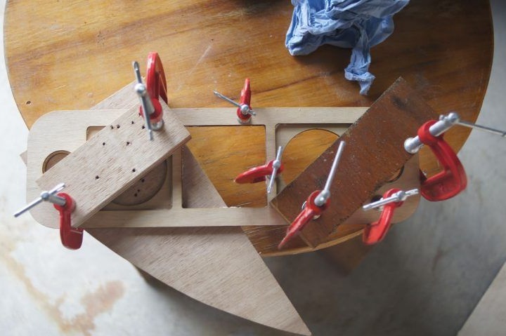
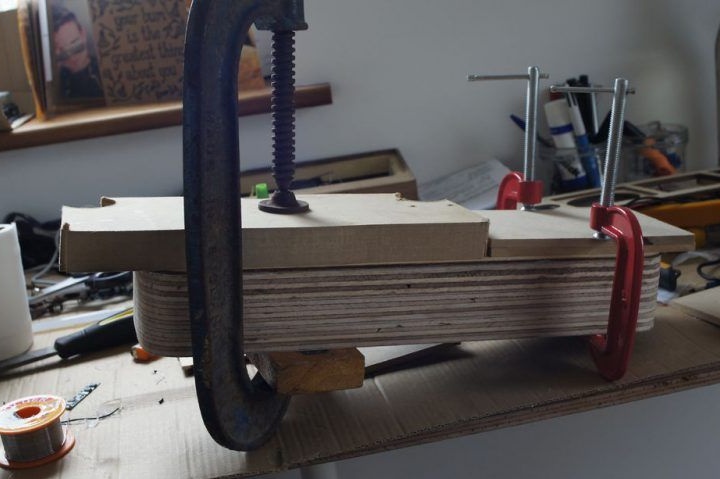
Step Two: Bonding Side Panels

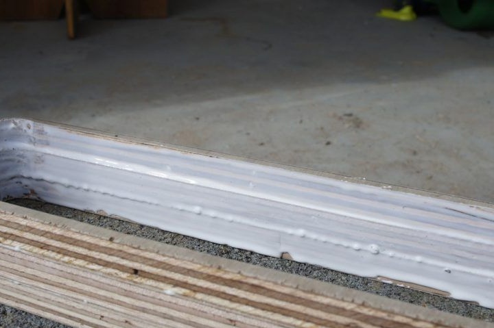
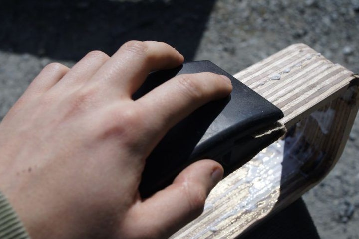
After the outer panels were cut, the author proceeded to glue them in several layers in order to achieve a thickness of 18 mm. This will give strength to the hull. The plywood parts were glued together using carpentry glue, after which the panels were clamped in clamps and held so until completely dry.
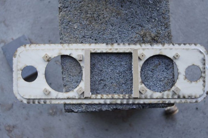
Step Three: Preparing the Back Panel
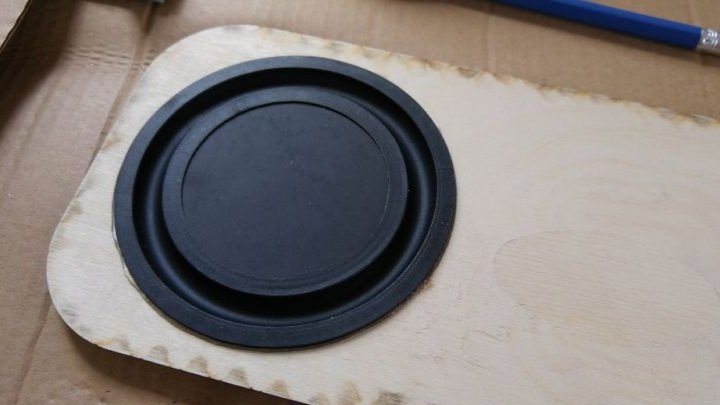
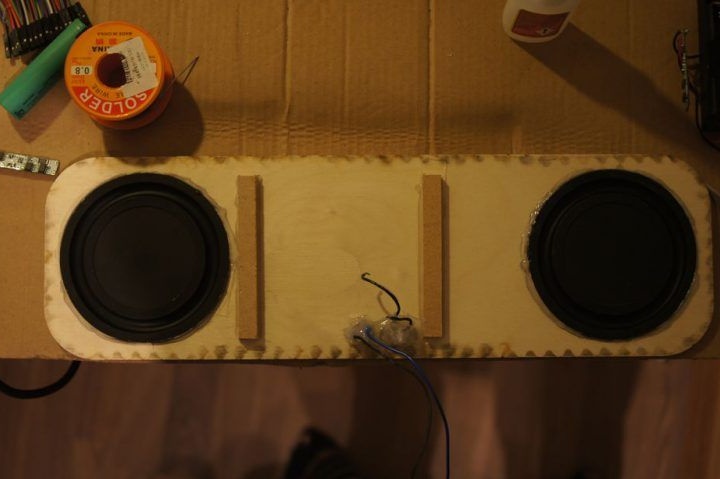
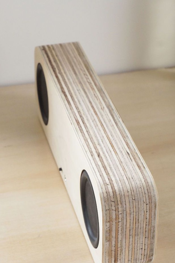
Passive membranes were glued to the assembled rear panel, which increase the range of the speakers, responding to pressure drops inside the device. Therefore, it will be important to seal the case at the end of the work. The membranes were glued onto helium super glue, it will allow the membranes to move slightly and thereby protect them from damage.
To make the back wall even stiffer, the author decided to add several MDF strips.
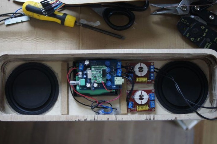
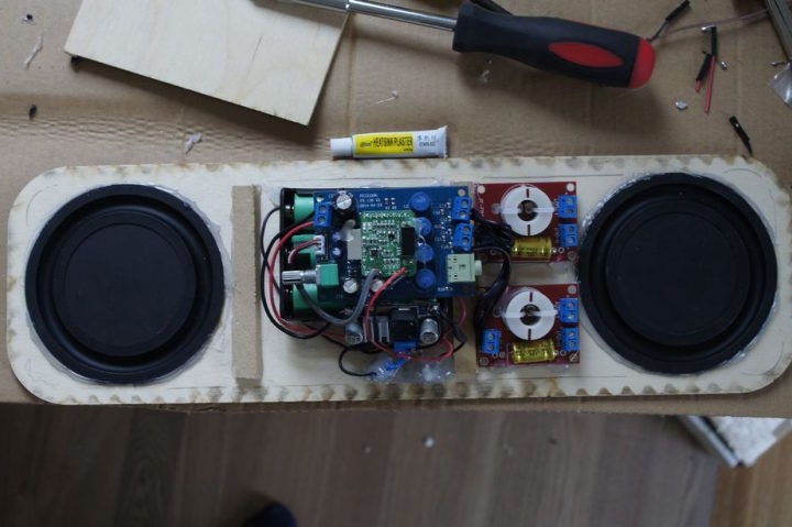
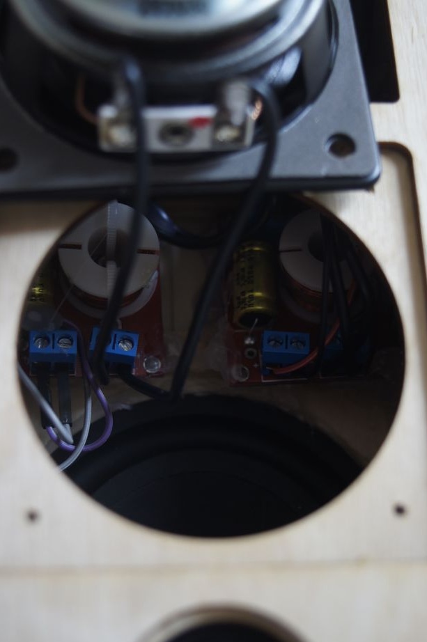
Step Four: Placing Electronics
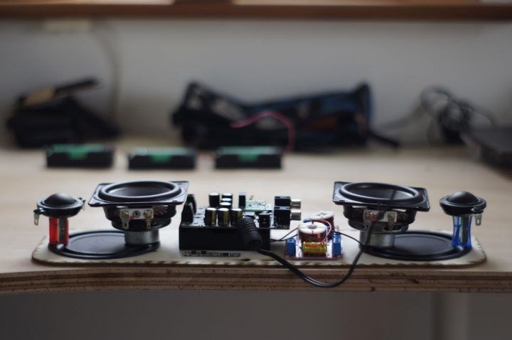
When installing electronics inside the case, the author was guided by the rule of easy accessibility of breaking components, so that in the future it would not be necessary to completely disassemble the column to replace them. It is also important to make an approximate calculation before installation, so that all the necessary elements are installed correctly inside the case.
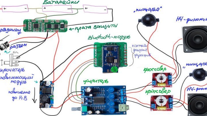
Further, the author began creating an electrical circuit for the functioning of the device.
Below is a diagram of the assembly circuit of the column.
Step Five: Battery Operation
The author used fairly cheap Samsung’s pink 18650 batteries.To protect them, a board was installed that will prevent overcharging, excessive discharge, give protection against short circuit and more. Using a board to protect lithium-ion batteries is very important. It is also important to pay special attention to the choice of a charging device.
Step Six: Battery Assembly
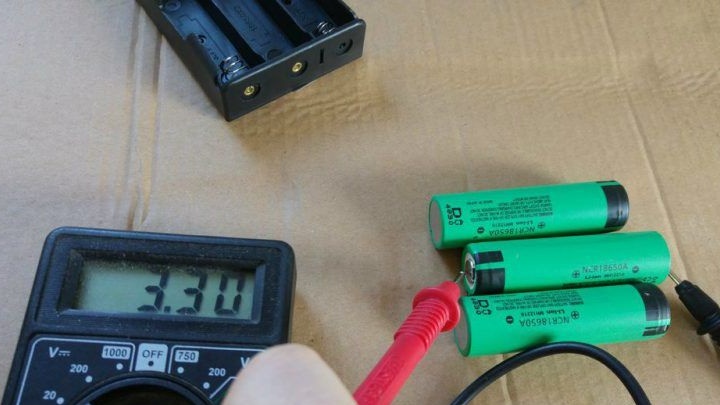


Before you start creating a battery pack from batteries, you need to make sure that the voltage of all batteries has the same value. This is important, as different battery levels in the circuit will confuse the protection board and may lead to premature battery failure.
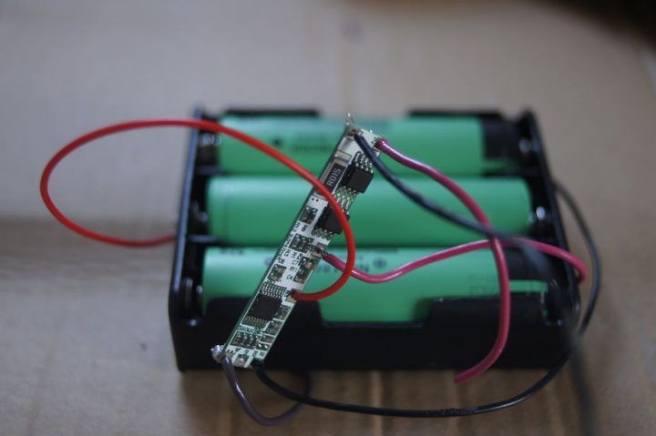
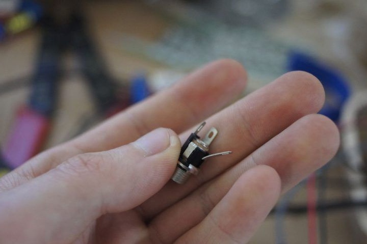
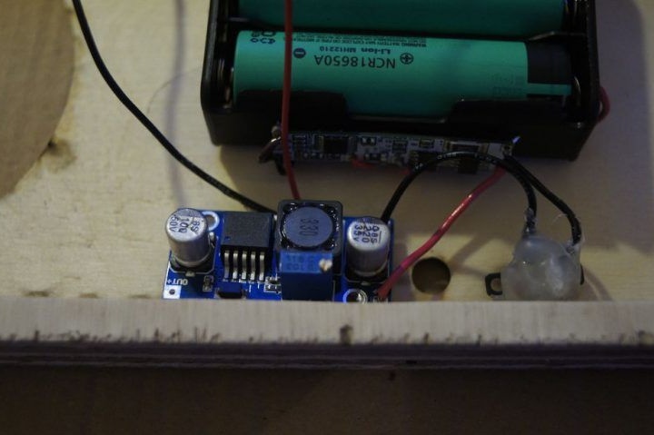
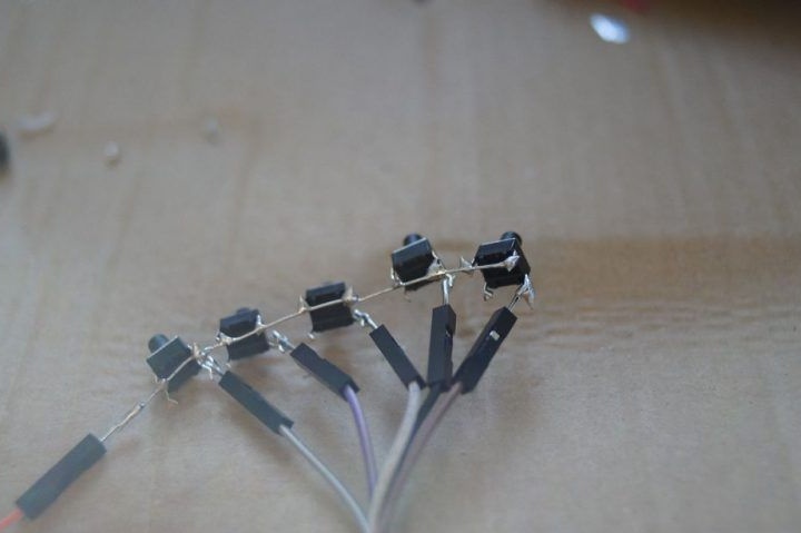
To connect the batteries into a single battery, a purchased case was used, where they will be compactly located. In the case, the wiring connecting the batteries to the thicker ones was soldered, for more reliable operation of the device. Then, a protective board and a switch with a power connector were soldered to this case. The power connector should be given special attention: the right bent contact can be removed completely, and the left can be connected to ground, the middle one will be positive. To verify the correct polarity of all contacts, the author recommends walking with a multimeter and checking the voltage. After making sure that everything is done correctly, it will be possible to start soldering the connector into the protection circuit.
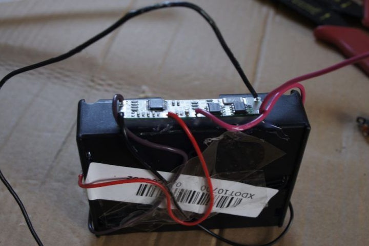
Then you should check the operability of the entire power circuit. After that, the wires are fixed to the case on the tape. Then the author soldered the voltage converter. For the device to operate, a voltage of 14 V is required, so with the help of a screwdriver and a multimeter, the converter was adjusted accordingly by twisting the copper screw on its board.
Seventh step: Connecting a Bluetooth module and amplifier
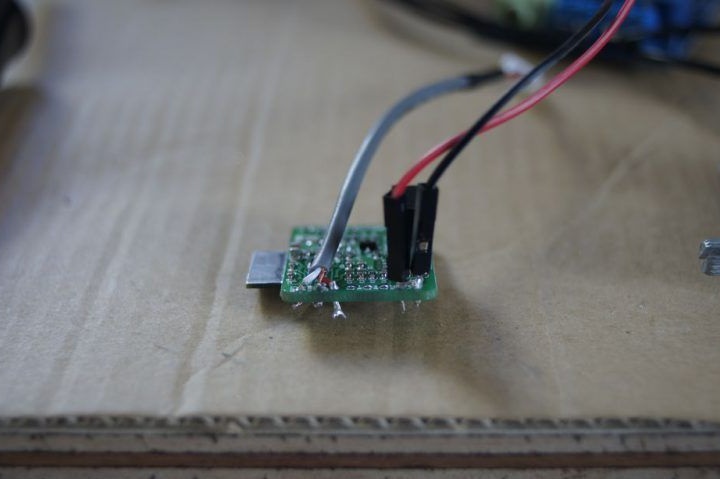
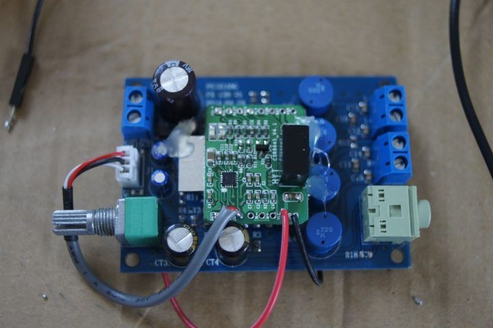
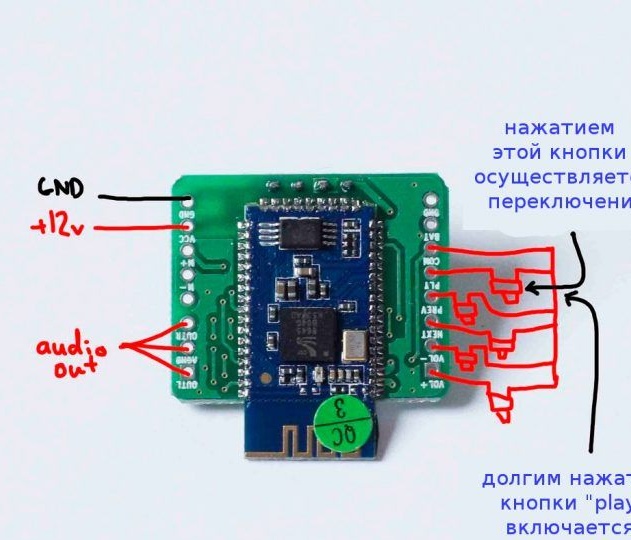
To leave more space in the case, the author decided to attach the Bluetooth module directly to the amplifier board. In this case, it is important to leave enough space between the amplifier and module chips, as these microcircuits can heat up and require air flow. In addition, when they touch, a short circuit may occur. The amplifier and module circuit boards were fastened with hot glue, so that the circuit board chips were far enough apart. It is important to understand that when using a Bluetooth module operating from 5 W, it is necessary to connect a grounding insulator to the power supply cable of the module, as otherwise, it will create interference that will affect the sound quality.
Then the output contacts of the module were connected to the input contacts of the amplifier. Then the power contacts of the amplifier were connected to the output contacts of the converter. Thus, the amplifier will be powered from 14 V. The Bluetooth module will receive an input voltage of 10 to 12 V, depending on the voltage on the battery, because it is connected to the input contacts of the boost module. All this can be seen in the attached photos.
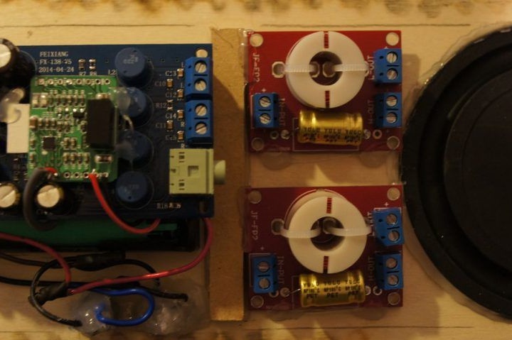
Step Eight: Connecting Crossovers
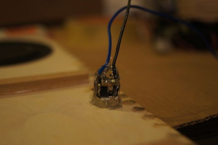
Crossovers should distribute the audio signal at high and low frequencies and direct them to the appropriate speakers. After they are soldered, they should be poured with hot glue for reliable fixation. By the way, applying hot glue to the corners of the case from the inside also contributes to the necessary sealing of the case.
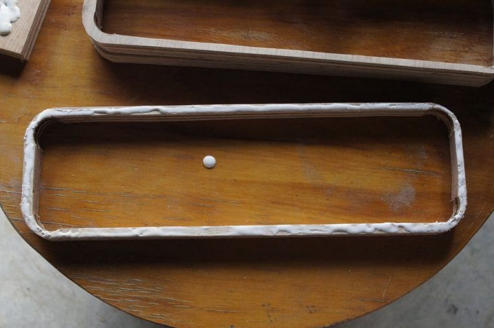
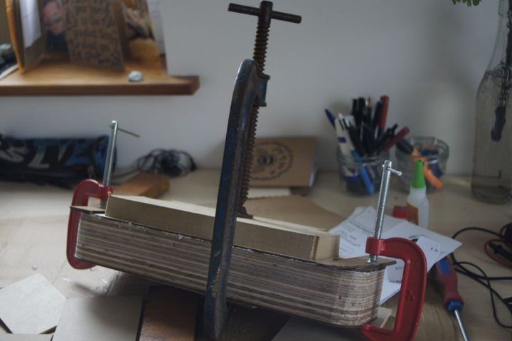
Step Nine: Adhesive Side Panel
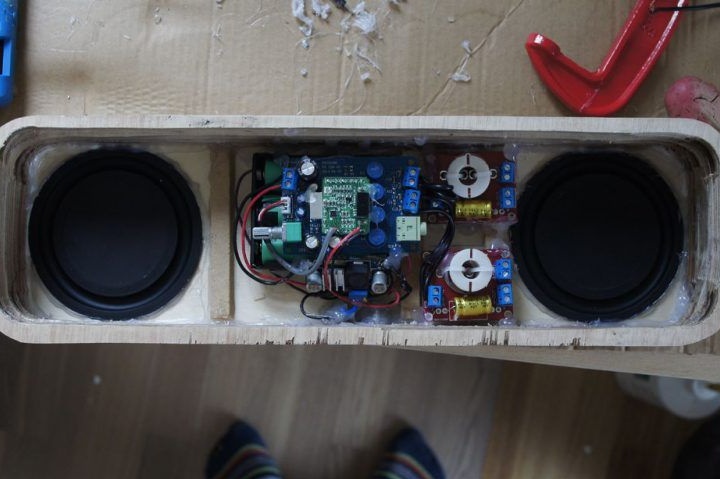
After installing all the elements, the side panel is glued. To do this, carpentry glue is applied along the edges of the panel, and it is pressed tightly. When the panel dries, the inner joint, like the rest, must be sealed with hot glue. This will not only improve the sound quality produced by the speaker, but also give additional strength to the entire body.
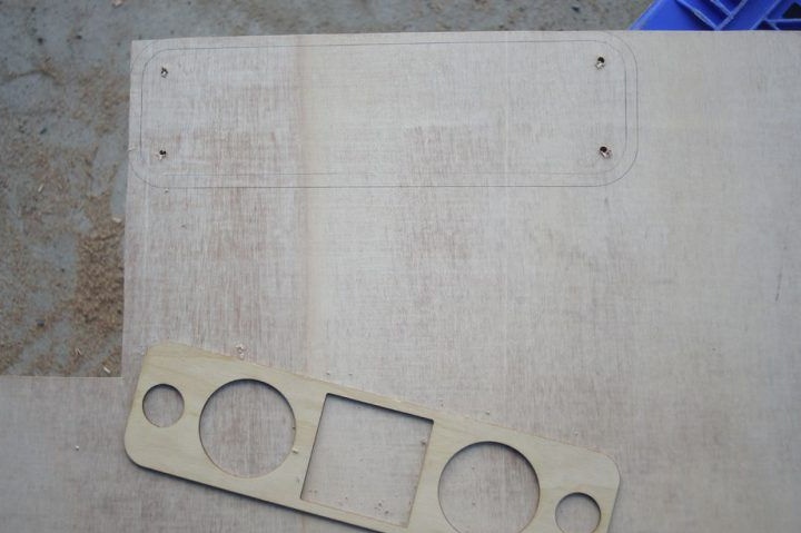
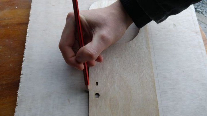
Step Ten: Preparing the Front Panel


To stiffen the front panel, additional MDF strips were also glued to it. Then tweeters were glued and wires from crossovers were connected to them. The panel is also mounted on glue and the joints are sealed.
Step Eleven: Maintenance Hole Cover


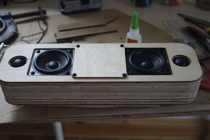
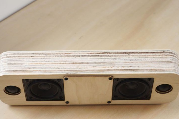
After assembling and drying the speaker enclosure, woofers are attached to the front panel. First, all the necessary wires are connected to the speakers, after which they can be fixed on the front panel with screws.
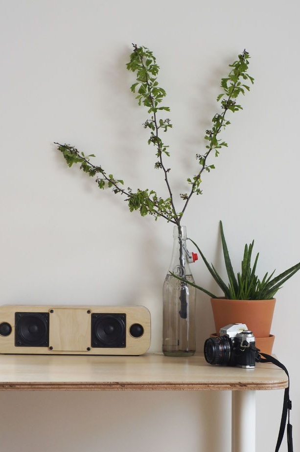
After that, the device will be practically ready for operation. After testing and making sure that all the speakers are working properly, the cover for the electronics service hole also closes. After that, the body of the product can be varnished to give it a store-like look.