
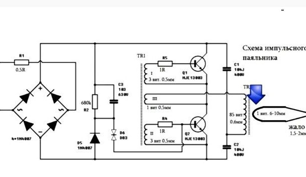
Such a soldering iron will come to the rescue always when you need to quickly solder something, but there is no time to wait until the usual soldering iron heats up. It can be assembled from a step-down power supply, the most important of which is a transformer. The tip will be connected to the secondary winding of the transformer, thereby forming a short circuit. According to the author, this will lead to heating of the tip of the soldering iron. The wire from which the sting is made is thinner in diameter than the transformer winding wire
Materials and tools for homemade:
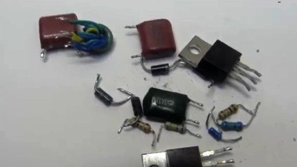
- unnecessary transformers for 50-60 watts;
- keys of the type MJE13003, MJE13005 or MJE 13007;
- copper wire with a diameter of 3.5 mm;
- a tube made of fiberglass or heat shrink;
- diode bridge (designed for 1A);
- lamp (for checking);
- clamps from mounting terminals;
- a tip for a soldering iron (the author took it from an industrial one);
- button on 220V and 1A.
The process of making a soldering iron:
Step one. Make transformer
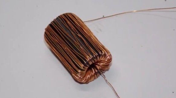
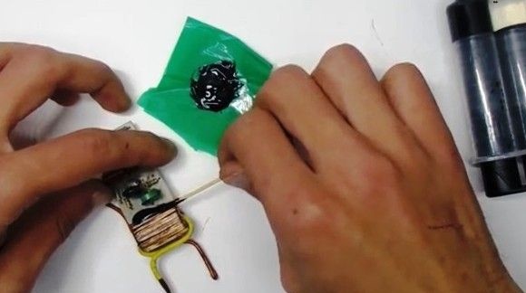
The author installed a transformer with a cylindrical ferrite core on the board. Such a core can be obtained in old power supplies, they are usually used as filters that smooth out interference. For the future soldering iron, such a core fit perfectly. What is the magnetic permeability of such a core is not known; therefore, the calculation of the winding did not occur. The primary winding of the transformer is wound around this core. Before winding the wire, it is desirable to wrap the core with insulating material, but the author did not have one at hand.
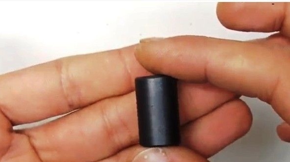
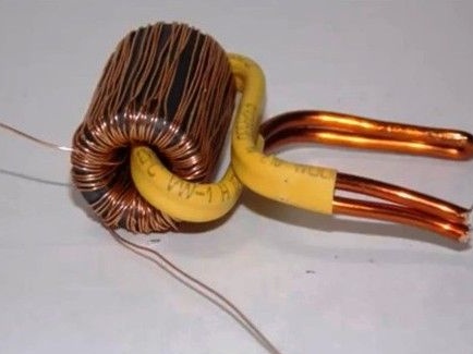
The secondary winding is made of a wire with a diameter of 3.5 mm, which folds in half. She has only one turn. Despite the fact that such a wire has a varnish coating, it can be damaged, and this can lead to unpleasant consequences. In this regard, it is recommended to wear a fiberglass tube or normal heat shrink on the wire.
To securely fix the transformer, it was glued to the board using epoxy.
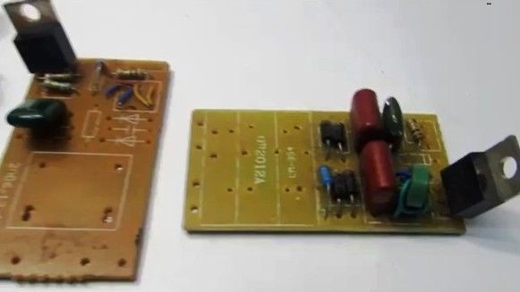
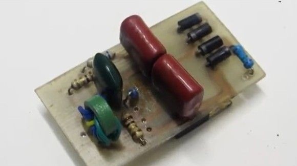
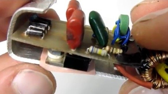
Step Two Transistors and diode bridge
The homemade diode bridge must withstand a current of 1A.It is also necessary to take into account that the transistors will warm up during the operation of the device, so for them it is necessary to organize a heat sink. Cases of transistors must be isolated from radiators.
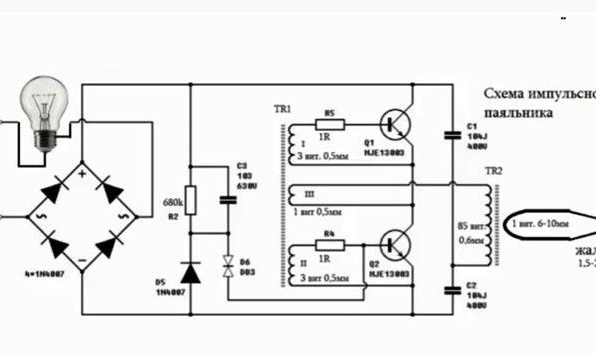
After the circuit is assembled, the device can be checked, while it is important not to forget about security. Checking homemade using a light bulb, exactly how to do this, can be seen in the diagram. If everything works, then the lamp turns off.
Step Three The final stage of assembly
The case is recommended to be made of a material with good thermal insulation, it can be fiberglass or hard rubber. But plastic is also suitable, because the temperature inside the device will not be so high as to melt it. But for natural ventilation, openings in the case still need to be made.

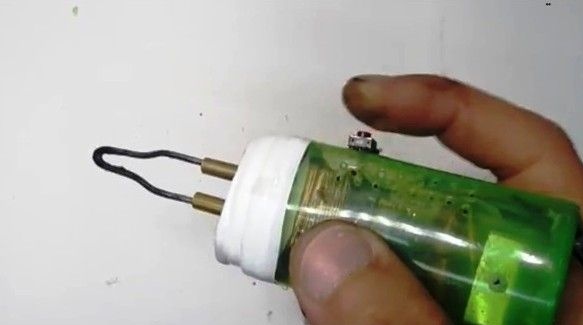
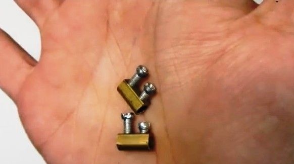
To make a soldering iron tip, the clamps from the mounting terminals fit well. The author took the sting from a similar soldering iron of an industrial assembly. It looks like a stainless steel, but copper wire will do. The soldering iron will work and it will be without problems.
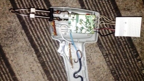
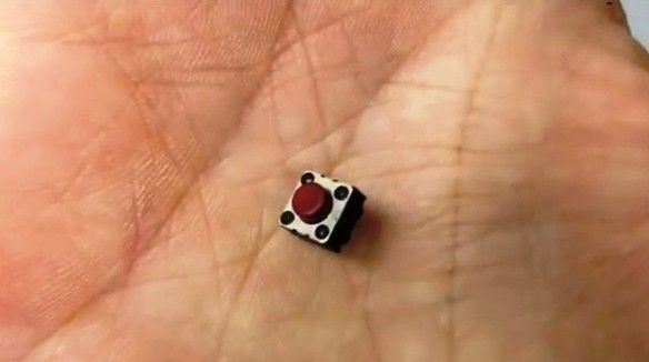
When starting the soldering iron, at the time of heating the tip, the device consumes 80 watts, despite the fact that the power supply is not more than 50-60 watts. When the sting heats up, the current consumption drops to 35-40 watts. If the sting will be made of copper wire, then it should be 1-2 mm in diameter. To start the soldering iron, press the button. The author does not recommend using such a button, as shown in the example. The button should be rated for 220V and current 1A.
The result is a lightweight and compact soldering iron. A couple of seconds after turning it on, it is already ready for work. If desired, the shape of the board can be slightly altered, it can be made narrower and longer. Then the soldering iron will become even more convenient.