
Recently become very popular homemade and industrial appliances with LEDs. Today they are found almost everywhere. They also start using LEDs instead of old tubular fluorescent lamps, but about incandescent lamps you can generally keep silent. Due to the fact that there is a huge variety of diodes, to test them it will be useful to get a tester, well, or make it do it yourself.
Of course, some LEDs can also be checked with a conventional multimeter in dialing mode. In this case, the LED should light up. But if it works under greater voltage than the multimeter gives out, the glow will be very weak, or it will not be at all.
For some white, yellow and blue LEDs, the voltage can reach 3.3V.
First of all, when testing an LED, you need to determine where it has a cathode and where is the anode. Of course, this can be determined by examining the insides of the crystal, but it takes time, effort, nerves, and indeed this is an unprofessional approach.
In addition, the manufactured probe will help determine what operating voltage the LED has, and this is a very important parameter. And finally, the device will help to trivially determine the health of the LED.
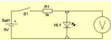
Device diagram
According to the author, the device diagram is very simple. Homemade is a prefix that sticks into the socket of a multimeter.
Materials and tools for homemade:
- a connecting block from the Krone battery;
- working battery crown (needed to power the probe);
- a miniature button without fixing (also a clock from a phone, tablet, etc.);
- one resistor 1 kOhm at 0.25 W;
- quick-detachable connector for transistors (socket with a pitch of 2.54 mm, only 3 contacts will be needed);
- material for creating a housing for the device (a plastic plate is suitable, etc.);
- four brass screws.
Homemade manufacturing process:
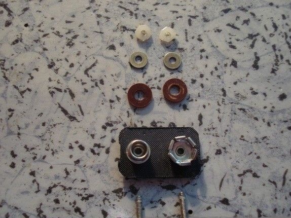
Step one. We prepare the necessary elements
First you need to prepare the contacts that will be connected to the multimeter.The photo shows that the pins are threaded, but it is best to get rid of it. Thread is needed only to screw the elements with nuts to the plastic case.
To fix the pins in the plastic plate, you need to drill the fourth holes. Two are needed to install a junction block through which the Krona battery is connected. And the second two are needed for mounting contacts, with which device connects to a multimeter.
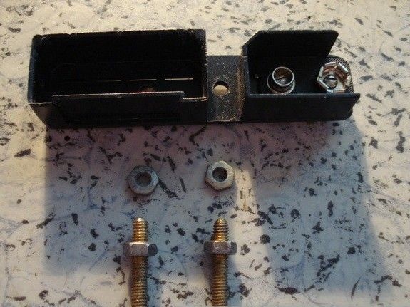
To fix the micro button and the connector for transistors, you will need to cut the board out of the PCB.
Step Two We solder the circuit
Now you need to solder electronic details, guided by the above diagram. You need to solder the micro button, transistor socket and 1 kΩ 0.25 W resistor.
Step Three The final stage. DIY assembly
Now the device is assembled in a common housing. The output wires are connected to the power supply for the Krona battery and to the plugs with which the probe is connected to the multimeter. On the PCB board near the connector, the author glued a circuit board, which allows you not to get confused when testing the LED. The red power wire is a plus, that is, the anode. Well, black with a minus is the cathode.
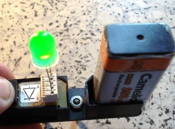
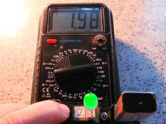
To test the LED, you need to plug it into the connector and connect the Krona battery to the socket. Now the multimeter switches to voltage measurement mode in the range of 2-20V DC. If the diode is healthy and turned on correctly, then it will light up.
As was said at the beginning, with the help of a multimeter it is possible to determine the operating voltage of the LED, but if this is not necessary, the multimeter will not be needed at all. That's all, the little helper is ready, now it will be much more pleasant and faster to assemble home-made products on LEDs or repair something.