
In this article, we will look at how you can make a simple chronograph from inexpensive and affordable parts. Device necessary in order to measure the speed of a bullet in a rifle. These figures are needed in order to determine the condition of the rifle, because over time, some parts of the pneumatic wear out and require replacement.
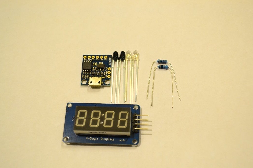
We prepare the necessary materials and tools:
- Chinese Digispark (at the time of purchase it cost 80 rubles);
- segment type display on TM1637 (costing 90 rubles when purchased);
- infrared LEDs and phototransistors (10 pairs) - the cost was 110 rubles;
- one hundred 220 Ohm resistors cost 70 rubles, but only two of them will be needed.
That's all, this is the whole list of items that you will need to buy. By the way, resistors can also be found in old household appliances. You can bet more at face value, but no less. As a result, you can keep within 350 rubles, but this is not so much, given that the factory chronograph will cost at least 1000 rubles, and the assembly there is much worse than ours homemade.
Among other things, you need to stock up on such details as:
- wires;
- a piece of pipe with a length of at least 10 cm (a plastic water pipe is suitable);
- all for soldering;
- multimeter (optional).
The first three details described have their own nuances, so each of them needs to be considered separately
Digispark
This item is a miniature circuit board that is compatible with ArduinoOn board she has an ATtiny85. How to connect this element to the Arduino IDE, you can read on, you can also download drivers for it there.
This board has several options, one uses microUSB, and the other is equipped with a USB connector, which is wired directly on the board. Due to the fact that the homemade product does not have an individual power supply, the author chose the first version of the board. If you install a battery or a battery in a homemade product, this will greatly increase its price, and will not greatly affect practicality. Almost everyone has a cable for charging mobile and Power bank.
As for the characteristics, they are similar to ATtiny85, here its capabilities are abundant. The microcontroller in the chronograph only interrogates the sensors and controls the display.
If you have never met Digispark before, the most important nuances can be found in the table.
It is important to consider the fact that the pin numbering for the analogRead () function has differences. And on the third pin is a pull-up resistor with a nominal value of 1.5 kOhm, since it is used in USB.
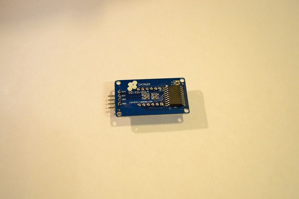
A few words about the display
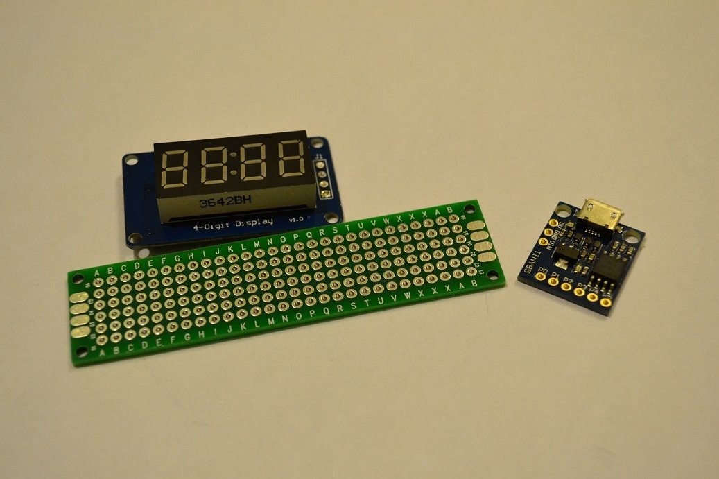
Anyone can use the display for homemade, but the author opted for a cheap option. To make the device even cheaper, you can completely abandon the display. Data can simply be output via cable to a computer. It will be needed here. The display in question is a copy of the display.
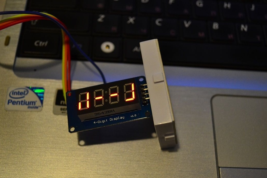
How the display looks in front and behind can be seen in the photo.
Since the distances between the numbers are the same, when the colon is off, the numbers are read without problems. The standard library is capable of displaying numbers in the range 0-9. letters in the range a-f, and there is still the opportunity to change the brightness of the entire display. Digit values can be set using the display function (int 0-3, int 0-15).
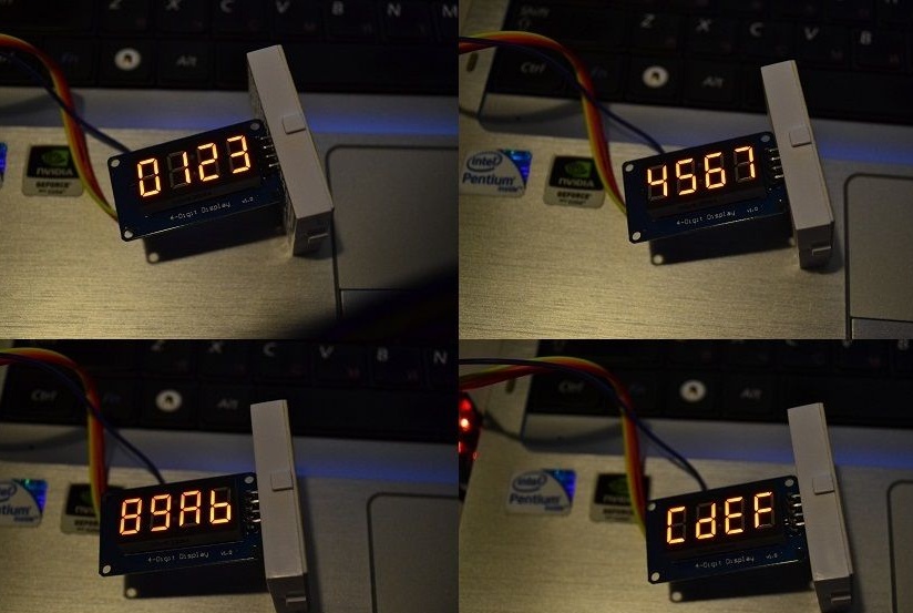
How to use the display

If you try to go beyond the values of [0, 15], the display will show confusion, which, in addition to everything else, is not static. Therefore, to display special characters, such as degrees, minuses, etc., you have to tinker.
The author wanted the display to display the finished energy of the bullet’s flight, which would be calculated depending on the speed of the bullet and its mass. The values according to the idea had to be displayed sequentially, and in order to understand where which one should be noted somehow, for example, using the letter "J". In extreme cases, you can simply use the colon, but the author did not like it, and he climbed into the library. As a result, the setSegments function (byte addr, byte data) was made on the basis of the display function, it lights up the segments encoded in data in the number with addr number:
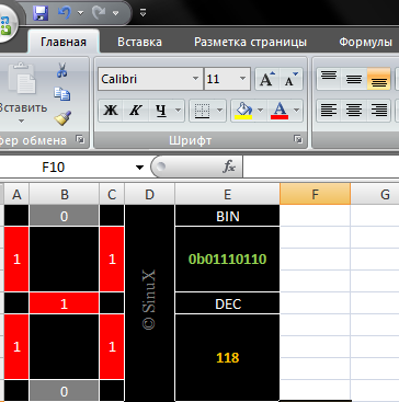
Such segments are encoded quite simply, the least significant bit of data is responsible for the upper segment, and then clockwise, the 7th bit is responsible for the middle segment. The character "1" when encoded looks like 0b00000110. The eighth most significant bit is responsible for the colon, it is used in the second digit, and in all others it is ignored. Subsequently, the author automated the process of obtaining codes using Excel.
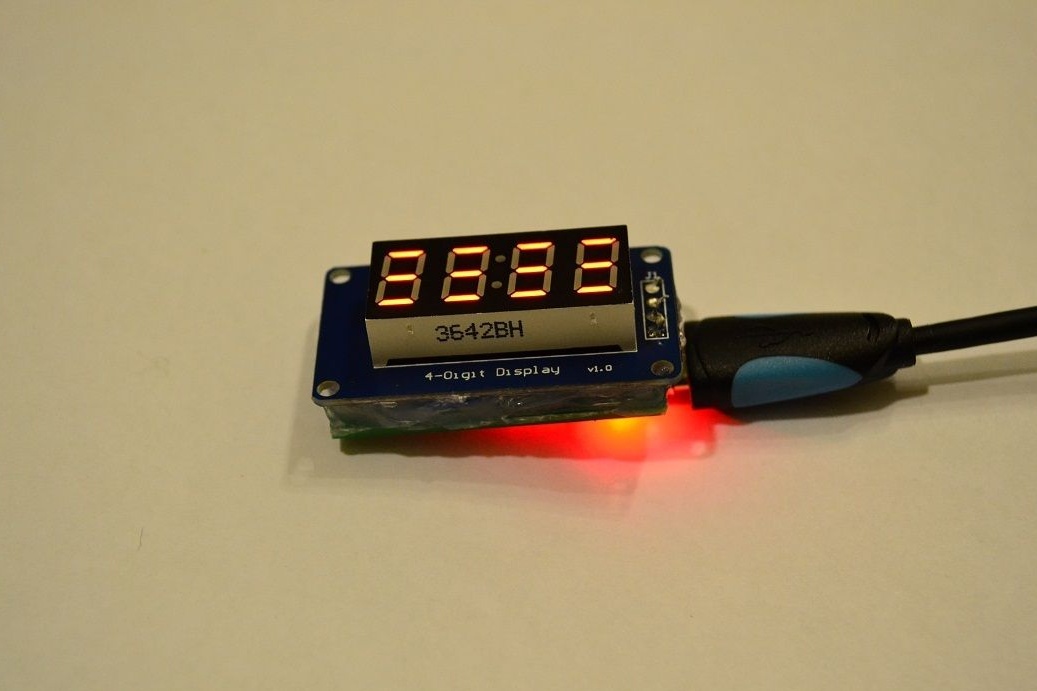
What eventually happened can be seen in the photo
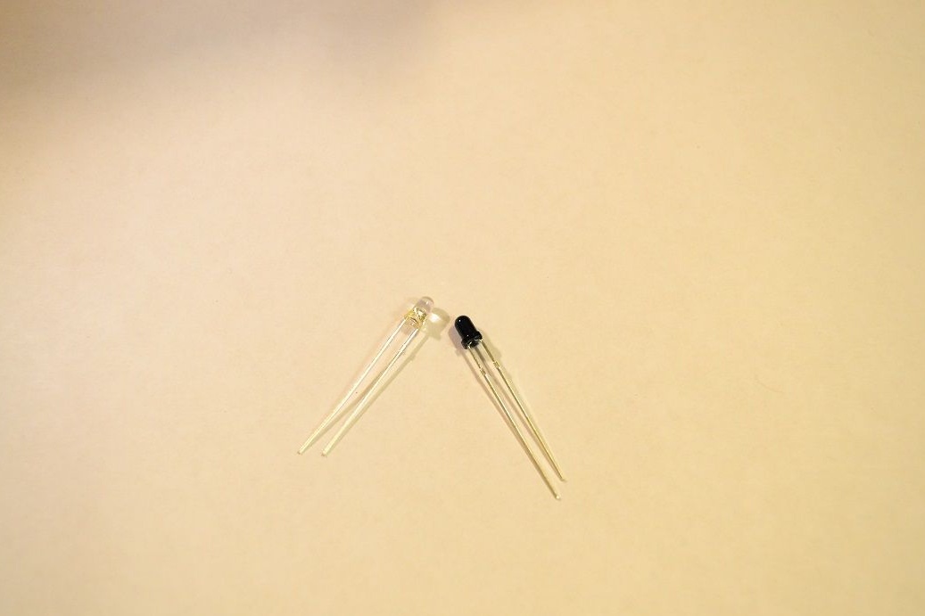
Finally, the sensors
No accurate information was provided about the sensors, it is only known that they have a wavelength of 940 nm. During the experiments, it was found that the sensors are not able to withstand currents of more than 40 mA. As for the supply voltage, it should not be higher than 3.3V. As for the phototransistor, it has a slightly transparent body and reacts to light.
We proceed to the assembly and configuration of homemade:
Step one. Assembly
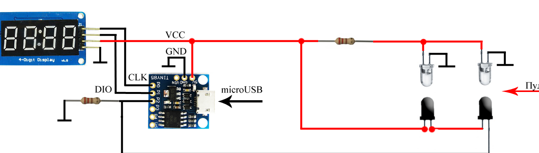
Everything is going in a very simple way. Of all the pins, only P0, P1 and P2 will be needed. The first two are used for the display, and P2 is needed for the sensors.
As you can see, one resistor is used to limit the current for LEDs, but the second pulls P2 to the ground. Due to the fact that phototransistors are connected in parallel, when the bullet passes in front of any optocoupler, the voltage on P2 will drop. To determine the flight speed of a bullet, you need to know the distance between the sensors, measure two power surges and determine the time during which they occurred.
Due to the fact that only one pin will be used, it does not matter which side to shoot from. Phototransistors will notice a bullet anyway.
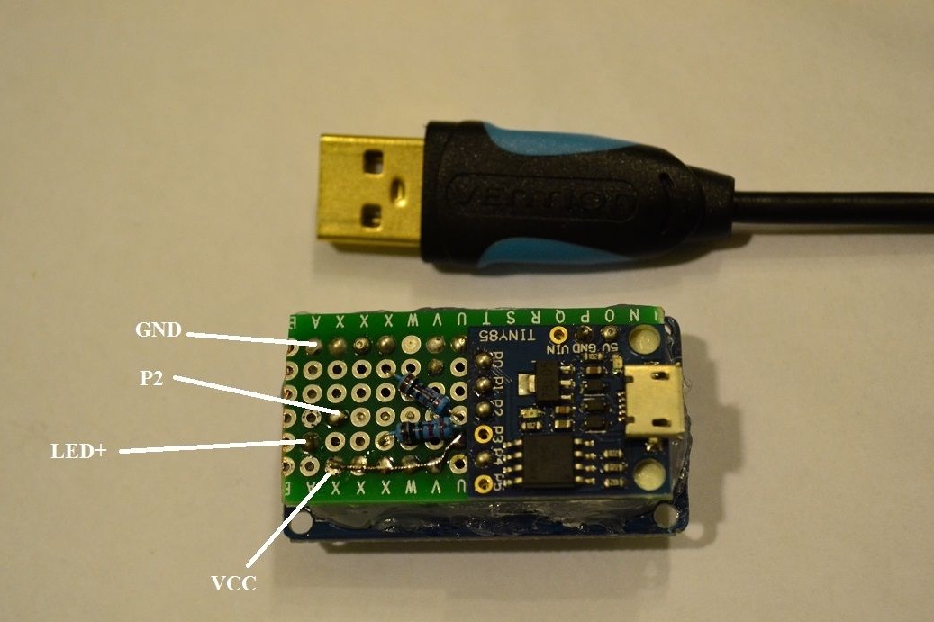
All of the details that are visible in the photo are collected. To collect everything, the author decided to use a breadboard. Then the whole structure was covered with hot glue for strength. Sensors are placed on the pipe and wires are soldered to them.
To prevent the diodes from pulsating when powered by a power bank, the author installed an electrolyte at 100 mKf in parallel with the LEDs.
It is also important to note that the P2 pin was chosen for a reason, the fact is that P3 and P4 are used in USB, so now with the help of P2 there is an opportunity to flash homemade after assembly.
P2 is also an analog input, so there is no need to use interrupt. You can simply measure the readings between the current and previous values, if the difference becomes higher than a certain threshold, then at that moment the bullet just passes near the optocoupler.
Step Two Firmware
Prescaler is a frequency divider, in standard cases in boards like Arduino it is 128. This figure affects how often the ADC is polled. That is, for default 16 MHz, 16/128 = 125 kHz comes out. Each digitization consists of 13 operations, so the pin can be polled as much as possible at a speed of 9600 kHz. In practice, this is not more than 7 kHz. As a result, the interval between measurements is 120 μs, which is too much for the homemade work. If the bullet flies at a speed of 300 m / s, it will overcome a path of 3.6 cm during this time, that is, the controller simply will not be able to notice it. For everything to work properly, the interval between measurements should be at least 20 μs. For this, the divisor value must be equal to 16. The author made a divider 8, how to do this, can be seen below.
What happened to learn during the experiment, can be seen in the photo
The logic of the firmware has several stages:
- measuring the difference in values on the pin before and after;
- if the difference exceeds the threshold, then the loop goes out and the current time (micros ()) is remembered;
- the second cycle works similarly to the first and has a time counter in the cycle;
- if the counter has reached the set value, then an error message is sent and the transition to the initial state. In this case, the cycle does not go into eternity if the bullet was not suddenly caught by the second sensor;
- if there is no counter overflow and the difference in value is greater than the threshold, the current time is measured (micros ());
- Now, based on the difference in time and distance between the sensors, you can calculate the flight speed of the bullet and display information on the screen. Well, then it all starts all over again.
The final stage. Testing
If everything is done correctly, the device will work without problems. The only problem is the poor response to fluorescent and LED lighting, with a ripple frequency of 40 kHz. In this case, errors may occur in the device.
Homemade works in three modes:
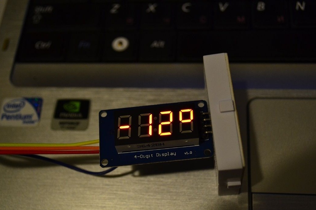
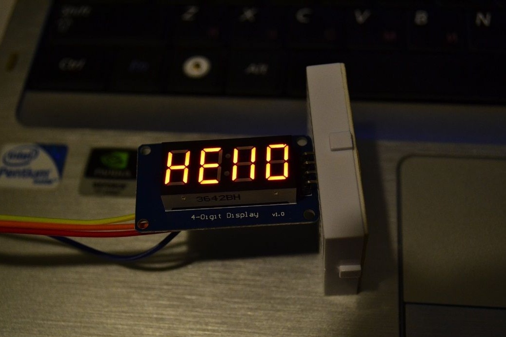
After turning on, there is a greeting, and then the screen is filled with stripes, this indicates that the device is waiting for a shot
If there are errors, the message “Err” is displayed, and then the standby mode is turned on.
Well, then comes the speed measurement
Immediately after the shot, the device will show the speed of the bullet (marked with the symbol n), and then information about the energy of the bullet (symbol J) will be displayed. When a joule is displayed, a colon is also displayed.