
 It often happens that you need to determine the polarity of the power source in a device. I came up with a solution to the problem for those who do not have a multimeter. This is a 4-diode polarity tester. Here is its appearance, it is quite small, therefore it will take up little space and will always come in handy when there are no special devices.
We will deal with the details
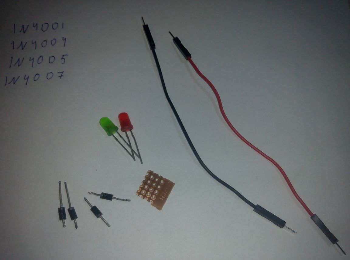
We need:
4 pcs diodes (model 1N4001 or analogues: 1N4004, 1N4005, 1N4007);
-LEDs red and green;
1KoM resistor;
-Two wires;
- a piece of the breadboard;
 We will deal with the circuit, if you want to make a tester up to 3 volts, then you can exclude the resistor from the circuit:
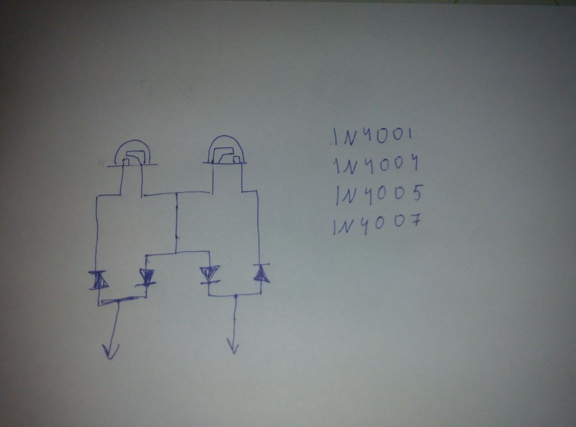 But we are considering specifically how to make a 6 volt tester
 We pass to assembly
First, install the LEDs
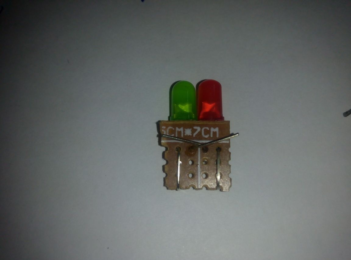 Next, you need to solder the cons of LEDs
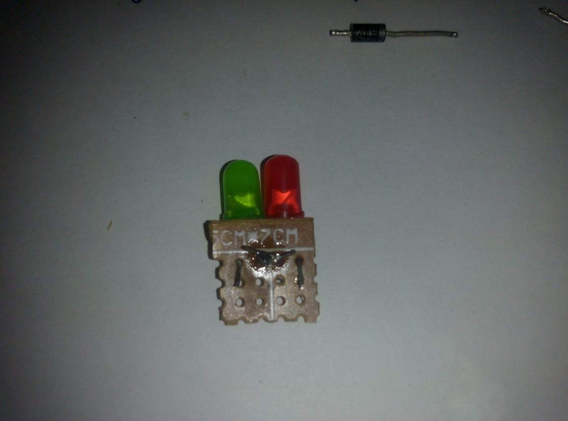 Further, according to the scheme, we connect all the details and get the option of a 3-volt tester
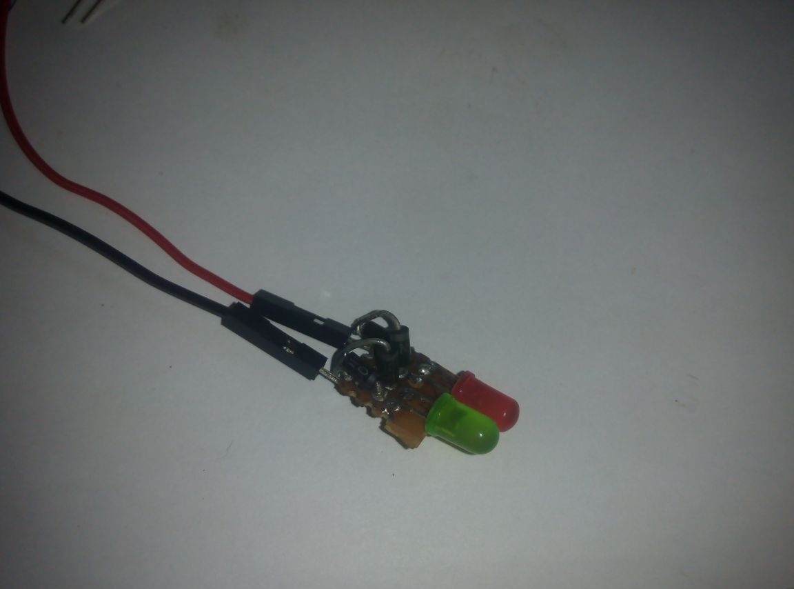 But our task is to make a 6-volt tester, therefore, following the diagram, we embed a resistor
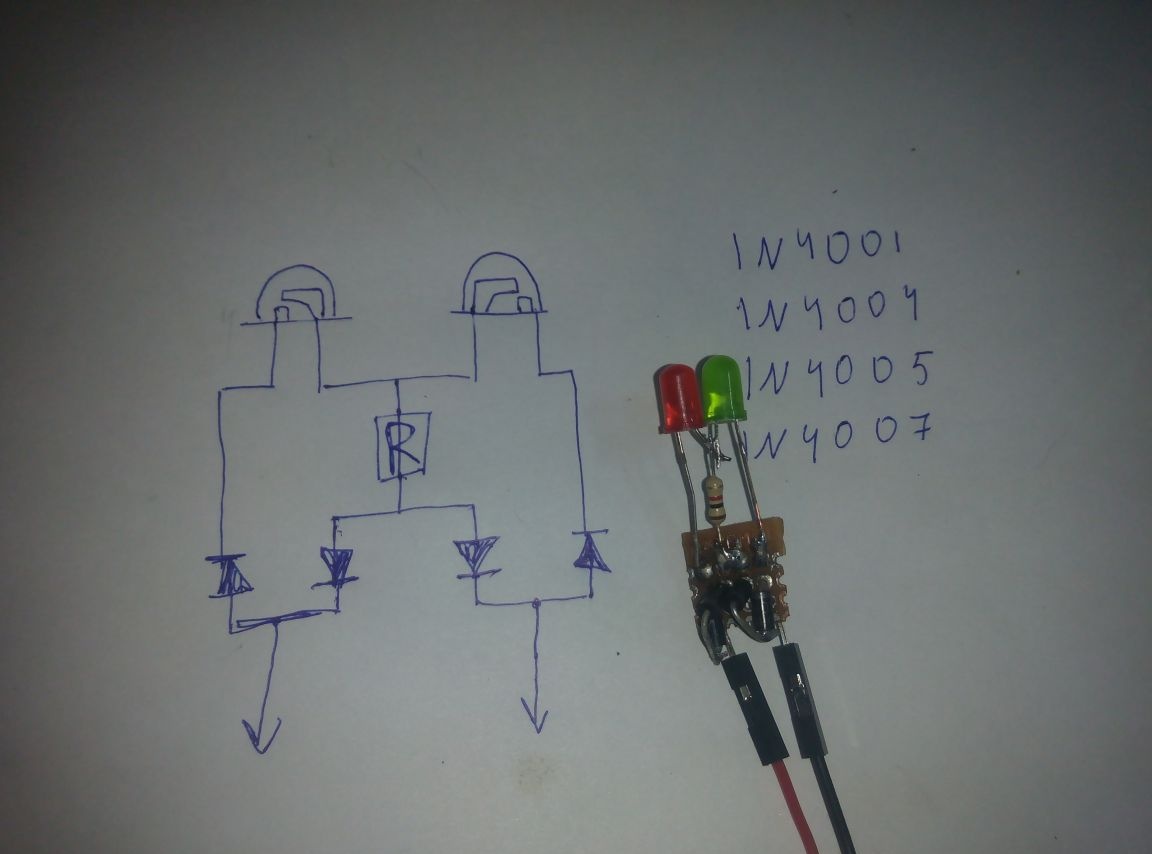 Next, solder wires of different colors, and everything can be tested.
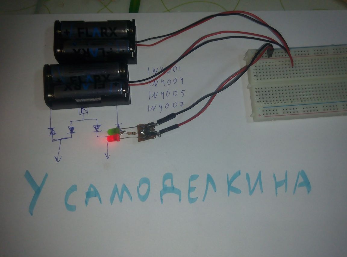
Before the test, we determine which diode determines the polarity. We take the battery, knowing its polarity, and connect it to the tester. Which LED will light up (if you correctly connected the wires: red with "+" and black with "-"), that will mean that the polarity is observed correctly.
The principle of operation is simple.when the polarity is observed correctly (black wire to “minus”, and red wire to “plus”), the LED that is selected as “determining” will light up, and if it is wrong, the other will light up.
I have a "defining" red LED
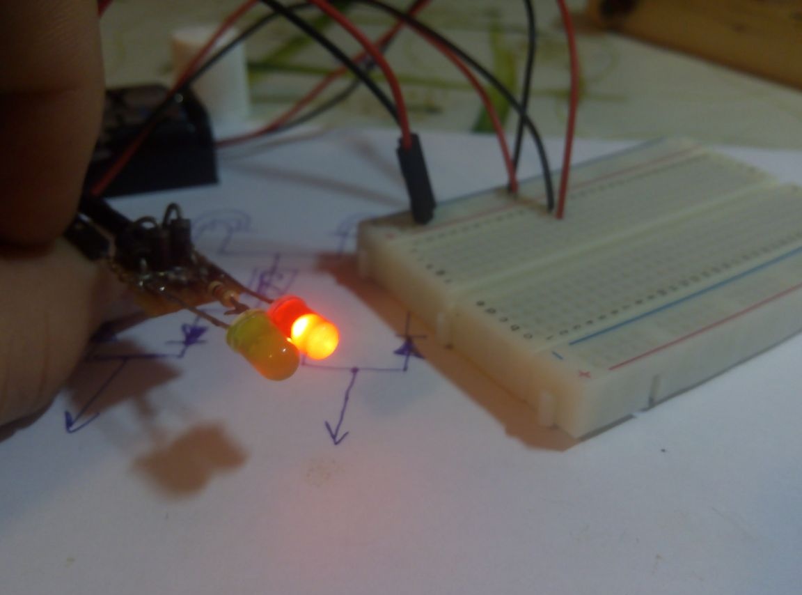 A green indicates that the polarity is not respected
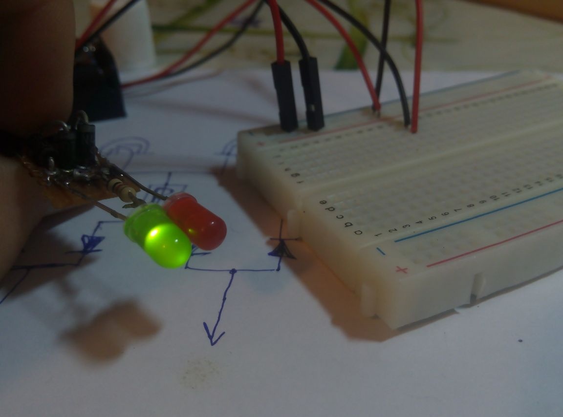 Well, if you are a beginner radio engineer, then I recommend making this tester, it will help in future projects, and also, with this example you can understand the principle of operation of diodes :)
Good luck, thanks for reading the article.