Initially, the thermostat was made simply as a thermometer to control the temperature outside the window. Then, during frosts, the potatoes began to freeze underground and functionality was added to control the microclimate. Passport data of the switching relay - 250V and 10A (2.5kW). Since the heat in the underground is not needed, a ten per kilowatt is enough.
Necessary materials and tools:shoe care box
-USB-charging for for the phone (any, at least 0.7A)
-
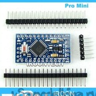
Arduino-Pro-Mini
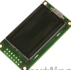
-2-line 8 character display (WH0802A-NGA-CT is more compact)
Encoder with a button (can be purchased in any radio mag, the button can be not built-in)
-schild with a 5V relay (I purchased a bunch of Chinese relays without optical isolation at one time, so I needed another Optocoupler PC817 and a 470 Ohm resistor. If you have optical isolation on the nameplate, you can connect the nameplate directly to the arduino port)
USB connector
-2 3-meter USB extension cable (one for the power cord, to the second we solder the DS1820)
- DS1820 (with any letter)
soldering iron
-glue gun
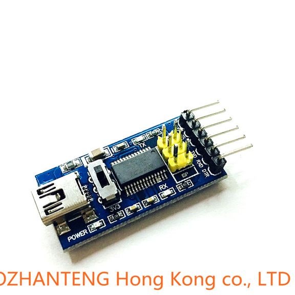
Nameplate FTDI232
Step 1: First of all, we need to flash the arduino, because I have a Pro Mini (it goes without a USB-RS232 converter), I need to solder a ruler with pins to the arduino. From the side where DTR, TXD, RXD, VCC, GND, GND are derived. Now we connect FTDI232 DTR to DTR, VCC to VCC, GND to GND, TXD to RXD, RXD to TXD. Run the arduino IDE, download the sketch and flash it (sketch at the end).
Step 2: Now let's take care of the hull. We tear off the sponge at the “FUKS”, degrease everything well, the deep part of the box can be passed with an emery cloth (something would stick more firmly). Mark the hole for the encoder, USB-connector (mother) and the display itself. Glue the relay to the box cover. We must try to place the relay farther from the processor and arrange the components so that the lid closes later (there is plenty of space).
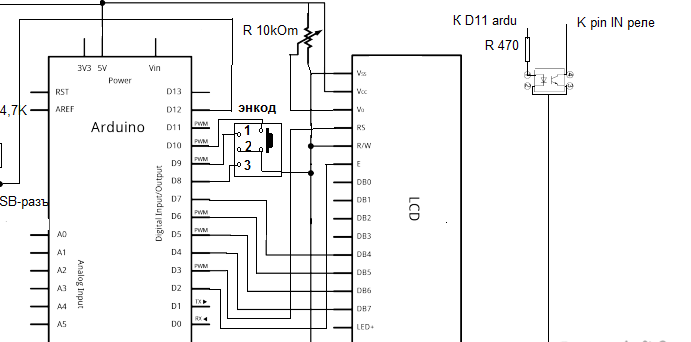
Step 3: Now we take the USB extension cable, cut off the connector socket (mother). We cut off the cut end, drill a hole for the cable in the body, insert it and glue the key with a gun. Plus, the cable has red, minus black (I just check it), plus the plus of the connector, minus the minus (I don’t give the pinout of the connector - it’s on the Internet). Between the plus of the connector and 2 medium (I have them connected), a 4.7kOhm resistor must be soldered.
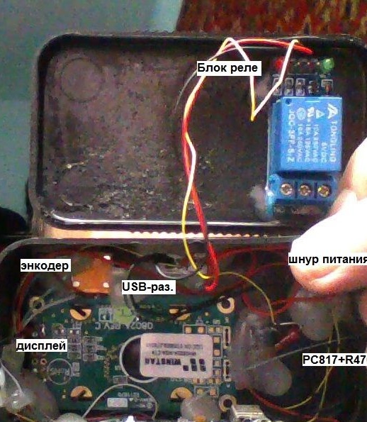
Step 4: We take 2 USB extension cables, cut off the connector (mother), cut the cable. Just in case, we’ll check whether we all correctly soldered. We connect the power cable with USB charging and to the network, stick the cut cable into the USB connector, look at the tester + on red - on black. We pull out the cable and solder the DS1820: - to 1, + to 3 the remaining 2 wires to 2. I then coat the epoxy compound (for repair of tanks, radiators), leaving a little of the sensor housing outwards, so that there would be a faster reaction to temperature changes.Well, we do the installation according to the circuit diagram (we connect the power and ground of the relay plate with the common + and - circuits, respectively).
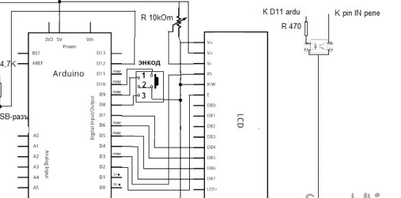
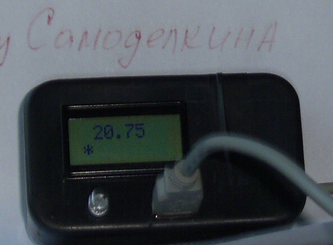
Step 5: All circuit components are connected. We connect our sensor (without it, the display will remain black), apply power. In the first line - the temperature, in 2 if “*” is on - the relay is on, no - off. Now let's try to set the relay switching limits. Press the encoder shaft (or your button) the limit value appears at which the relay will turn on by rotating the shaft - the value increases or decreases. By clicking on the shaft again - we get the upper limit (the relay will turn off), set the value and press again. The device will monitor the temperature, the value of the limits is maintained when the power is turned off. All.
#include
#include
#include
#define BUTTON_1_PIN 10 // the output number of button 1 is 12
OneWire ds (12); // on pin 10 (a 4.7K resistor is necessary)
// initialize the library with the numbers of the interface pins
Liquid Crystal lcd (3, 2, 4, 5, 6, 7);
unsigned long currentTime;
const int pin_A = 8; // pin 12
const int pin_B = 9; // pin 11
unsigned char enc_A;
unsigned char enc_B;
unsigned char enc_A_prev = 0;
float n_pr = 24.1;
float b_pr = 26.2;
boolean priz = false;
class Button {
 public:
  Button (byte pin, byte timeButton); // constructor description
  boolean flagPress; // flag button is now pressed
  boolean flagClick; // flag button was pressed (click)
  void scanState (); // method for checking the signal state
void setPinTime (byte pin, byte timeButton); // method for setting the output number and confirmation time (number)
 private:
  byte _buttonCount; // stable state confirmation counter
  byte _timeButton; // button state confirmation time
  byte _pin; // pin number
};
Button button1 (BUTTON_1_PIN, 30);
void knopka () {
 lcd.clear ();
 lcd.setCursor (1,0);
 lcd.print (n_pr);
// button1.scanState ();
 while (button1.flagClick == false) {
  enc_A = digitalRead (pin_A);
  enc_B = digitalRead (pin_B);
  if ((! enc_A) && (enc_A_prev)) {
   if (enc_B) {
    n_pr = n_pr-0.1;
   } else {
    n_pr = n_pr + 0.1;
   }
 lcd.clear ();
 lcd.setCursor (1,0);
 lcd.print (n_pr);
  }
  enc_A_prev = enc_A;
  button1.scanState ();
 }
 button1.flagClick = false;
 lcd.clear ();
 lcd.setCursor (1,0);
 lcd.print (b_pr);
 while (button1.flagClick == false) {
  enc_A = digitalRead (pin_A);
  enc_B = digitalRead (pin_B);
  if ((! enc_A) && (enc_A_prev)) {
   if (enc_B) {
    b_pr = b_pr-0.1;
   } else {
    b_pr = b_pr + 0.1;
   }
 lcd.clear ();
 lcd.setCursor (1,0);
 lcd.print (b_pr);
  }
  enc_A_prev = enc_A;
  button1.scanState ();
 }
 button1.flagClick = false;
 if (n_pr> b_pr) {
  float wr = n_pr;
  n_pr = b_pr;
  b_pr = wr;
 }
 int addr = 0;
 EEPROM.write (addr, 'y');
 addr = 1;
 EEPROM.put (addr, n_pr);
 addr + = sizeof (float);
 EEPROM.put (addr, b_pr);
 delay (300);
}
void setup (void) {
 pinMode (11, OUTPUT);
 pinMode (pin_A, INPUT_PULLUP);
 pinMode (pin_B, INPUT_PULLUP);
 lcd.begin (8.2);
 int addr = 0;
 char c = EEPROM.read (addr);
 addr = addr + 1;
 if (c == 'y') {
  EEPROM.get (addr, n_pr);
  addr + = sizeof (float);
  EEPROM.get (addr, b_pr);
 }

// Serial.begin (9600);
}
void loop (void) {
 byte i;
 byte present = 0;
 byte type_s;
 byte data [12];
 byte addr [8];
 float celsius;
 if (! ds.search (addr)) {
  ds.reset_search ();
  delay (250);
  return
 }

 if (OneWire :: crc8 (addr, 7)! = addr [7]) {
   return
 }
 // the first ROM byte indicates which chip
 switch (addr [0]) {
  case 0x10:
   type_s = 1;
   break;
  case 0x28:
   type_s = 0;
   break;
  case 0x22:
   type_s = 0;
   break;
  default:
   return
 }
 ds.reset ();
 ds.select (addr);
 ds.write (0x44, 1); // start conversion, with parasite power on at the end
 enc_A = digitalRead (pin_A);
 enc_A_prev = enc_A;
 currentTime = millis ();
 while ((millis () - currentTime) <2000) {
  button1.scanState ();
 if (button1.flagClick == true) {
  // there was a button click
  button1.flagClick = false; // reset click attribute
  knopka ();
 }
 }
// delay (1000); // maybe 750ms is enough, maybe not
 // we might do a ds.depower () here, but the reset will take care of it.

 present = ds.reset ();
 ds.select (addr);
 ds.write (0xBE); // Read Scratchpad
 for (i = 0; i <9; i ++) {// we need 9 bytes
  data [i] = ds.read ();
 }
 // Convert the data to actual temperature
 // because the result is a 16 bit signed integer, it should
 // be stored to an "int16_t" type, which is always 16 bits
 // even when compiled on a 32 bit processor.
 int16_t raw = (data [1] << 8) | data [0];
 if (type_s) {
  raw = raw << 3; // 9 bit resolution default
  if (data [7] == 0x10) {
   // "count remain" gives full 12 bit resolution
   raw = (raw & 0xFFF0) + 12 - data [6];
  }
 } else {
  byte cfg = (data [4] & 0x60);
  // at lower res, the low bits are undefined, so let's zero them
  if (cfg == 0x00) raw = raw & ~ 7; // 9 bit resolution, 93.75 ms
  else if (cfg == 0x20) raw = raw & ~ 3; // 10 bit res, 187.5 ms
  else if (cfg == 0x40) raw = raw & ~ 1; // 11 bit res, 375 ms
  //// default is 12 bit resolution, 750 ms conversion time
 }
 celsius = (float) raw / 16.0;
 lcd.clear ();
 lcd.setCursor (1,0);
 lcd.print (celsius);
 if (priz) {
 lcd.setCursor (0,1);
 lcd.print ('*');
 }
 if (n_pr! = b_pr) {
 if (celsius  b_pr) {
  digitalWrite (11, LOW);
  priz = false;
 }
 }
}
// button state check method
// flagPress = true - clicked
// flagPress = false - pressed
// flagClick = true - was clicked (click)
void Button :: scanState () {
if (flagPress == (! digitalRead (_pin))) {
  // signal state remains the same
  _buttonCount = 0; // reset the signal status counter
}
 else {
  // signal state has changed
  _buttonCount ++; // +1 to the signal state counter
  if (_buttonCount> = _timeButton) {
   // signal state did not change the specified time
   // signal state has become stable
   flagPress =! flagPress; // inverse of the status indicator
_buttonCount = 0; // reset the signal status counter
   if (flagPress == true) flagClick = true; // sign of click on click
  }
 }
}
// method for setting the output number and confirmation time
void Button :: setPinTime (byte pin, byte timeButton) {
 _pin = pin;
 _timeButton = timeButton;
 pinMode (_pin, INPUT_PULLUP); // define the output as input
}
// description of the constructor of the Button class
Button :: Button (byte pin, byte timeButton) {
 _pin = pin;
 _timeButton = timeButton;
 pinMode (_pin, INPUT_PULLUP); // define the output as input
}