» Electronics » Power supplies »Low voltage radio power supply

Low voltage radio power supply

Offered electronic BP, for powering a 6-volt (4 finger-type batteries) radio from a single battery with a voltage of 1.5 volts.


The proposed power supply unit (PSU) of the radio receiver is made on the basis of a low-voltage voltage converter 1.5 ... 6.0 volts and is designed to power low-power household devices (in particular, a radio receiver) from one finger batteryvoltage of 1.5 volts.


The inverter has good output with a minimum of input elements.

Photo 2 The appearance of the power cassette of the radio before finalization.


Photo 3 Tool


Photo 4Schemevoltage converter 1.5v - 6.0v

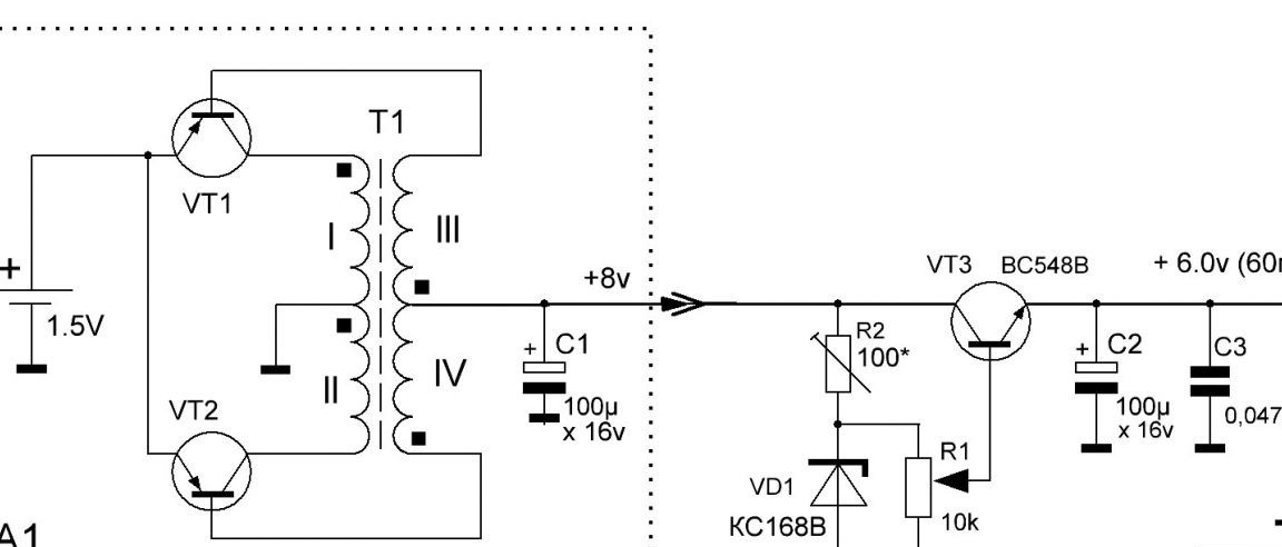
The transistors VT1 and VT2 assembled a push-pull high-frequency pulse generator (block A1) based on the circuit of A. Chaplygin, “Radio 11.2001, p. 42”. The positive feedback current flows through the secondary windings of the transformer T1 and the load connected between the + 6V circuit and the common wire. The pulse generator is followed by stabilization, adjustment and filtering nodes of the output voltage.


  • Instead of the RF voltage rectifier, the base-emitter transitions of the transistors of the generator itself are used, which eliminates the rectifier unit of the device.

  • The magnitude of the base current is proportional to the magnitude of the current in the load, which makes the converter very economical.

  • Due to the proportional current control of transistors, the losses on their switching are reduced and the efficiency of the converter is increased to 80%.

  • When the load is reduced to zero, the oscillation of the generator stalls, which can automatically solve the problem of power management.

  • The current from the battery, in the absence of load, is practically not consumed. The converter will turn on itself when it is required to supply something from it and turn off when the load is disconnected.


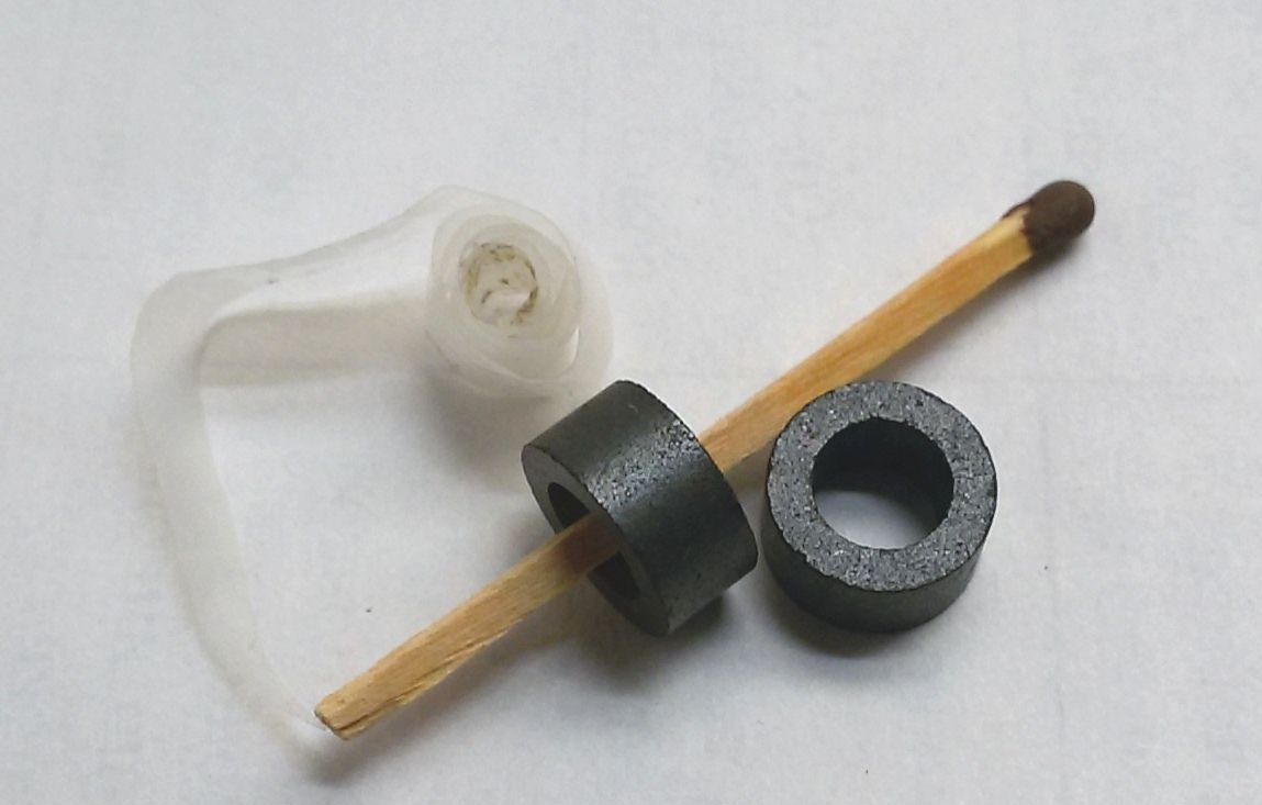
The magnetic circuit of the transformer T1 of the pulse generator is a K10x5x2 ring made of 2000NM ferrite (Photo 5). You can take the ring from the old motherboard.


Step 1. Prepare a ferrite ring before winding the transformer.In order to prevent the winding wire from damaging its insulation, blunt the sharp edges of the ring with a fine-grained sandpaper or file.


Photo 5 Ferrite ring and fluoroplastic tape


Step 2 Wind the insulating gasket onto the ring to prevent damage to the insulation of the wire (Photo 6). To do this, you can use tracing paper, lavsan or fluoroplastic tape.


Photo 6 Insulation rings


Step 3 Winding transformer windings: primary windings (I and II) - 2 x 4 turns, secondary windings (III and IV) - 2 x 25 turns of insulated PEV, PETV grades, diameter 0.15-0.30 mm. You can also use PELSHO, MGTF grades wire (Photo 7.9) or another insulated wire. This will lead to the formation of a second layer of the winding, but will ensure reliable operation of the voltage converter.


Each pair of windings is wound with a double-folded wire (Photo 7).


Photo 7 Windingtransformer


First, the secondary windings lll and lV (2 x 25 turns) are wound - (Photo 8).


Photo 8 Type of secondary windingstransformer III and IV


Then, also in two wires, the primary windings l and ll are wound (2 x 4 turns).

As a result, each of the double windings will have 4 wires - two on each side of the winding (Photo 9).

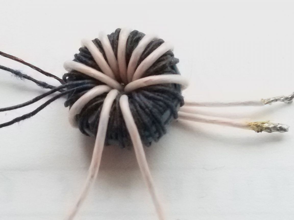
Photo 9 Viewtransformer after winding


When winding all the coils, one direction of the winding must be strictly observed and the beginning and end of the windings marked. If these conditions are not met, the generator will not start.


The beginning of each winding is marked on the diagram with a dot at the output. In order to avoid confusion, we can take for the beginning of all the windings of the wire extending from below, and for the end of all windings - conclusions from the top.


Step 4 We solder the wire of the end of the winding (III) and the wire of the beginning of the winding (IV). It turns out the secondary coil of the transformer T1 with a central output. We do the same with the windings l and ll of the primary coil.


For operation in low power converters, as in our case, transistors BC548V, A562, KT208, KT209, KT501, MP20, MP21 are suitable.


Transistors should be selected based on the permissible values ​​of the base current of the transistor (it must exceed the load current) and the reverse emitter-base voltage (it must exceed the output voltage of the converter).


We assemble the converter according to the scheme, on a universal mounting plate (Photo 10). The input, output and common bus of the converter are brought out by a flexible multicore wire.


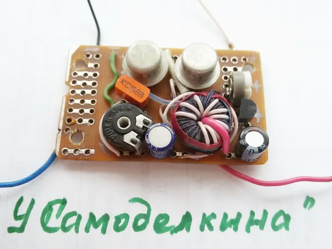
Photo 10 Converter 1.5 - 6.0 volts.

Photo 11 Converter (side view)


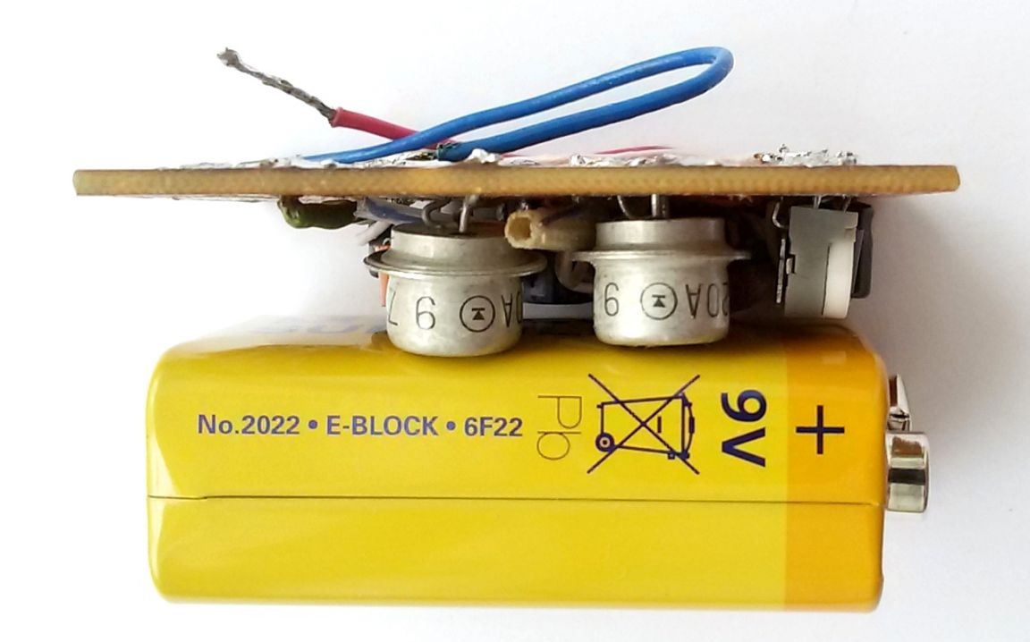
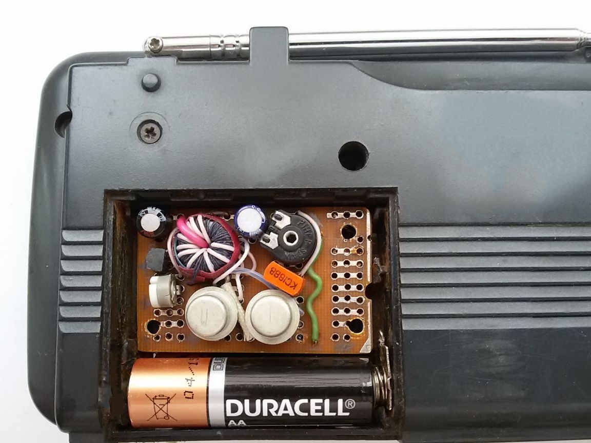
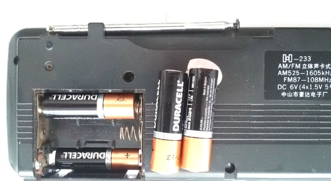
The converter board and AA battery (1.5V) are installed in the battery compartment of the radio.


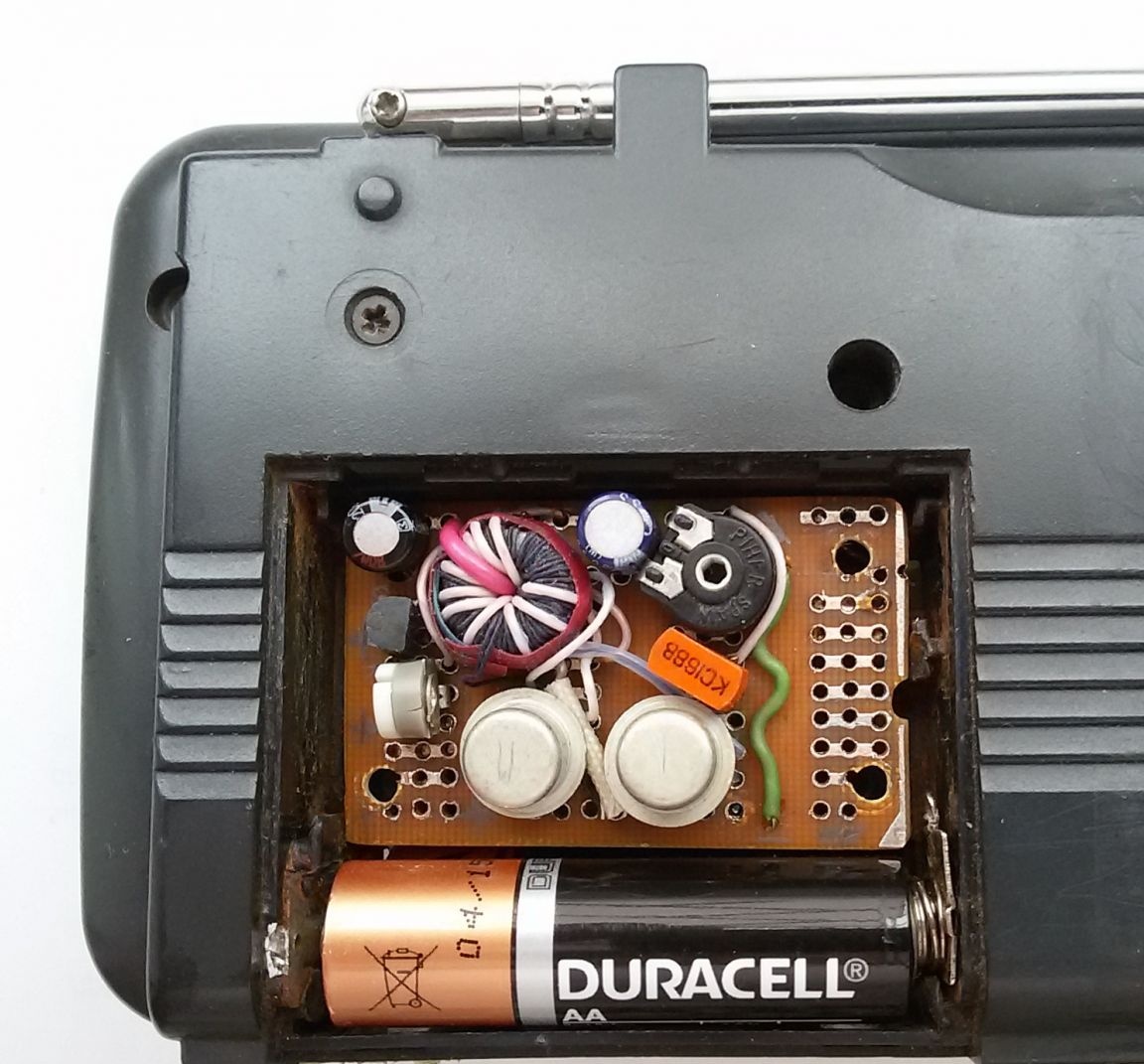
Photo 12 Placement of the converter with a battery in the receiver

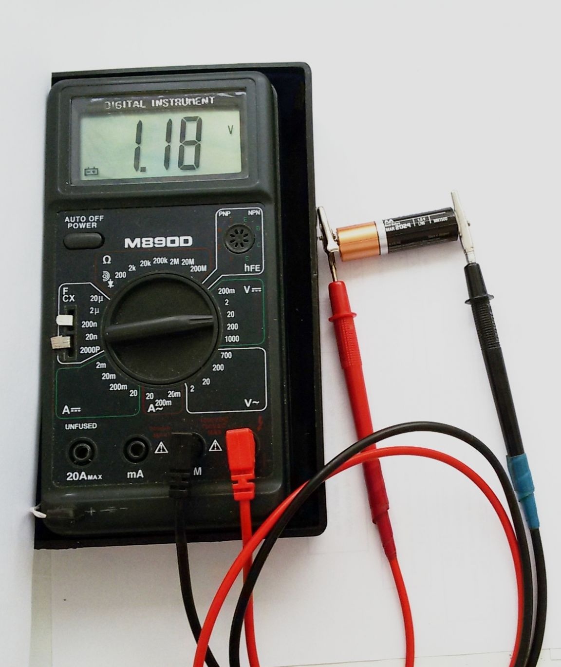
We check the correctness of the assembly of the converter, connect the battery and check with the device the presence and magnitude of the voltage at the generator output (+ 8V) and (+ 6V) at the BP converter.


Photo 13 Converter test


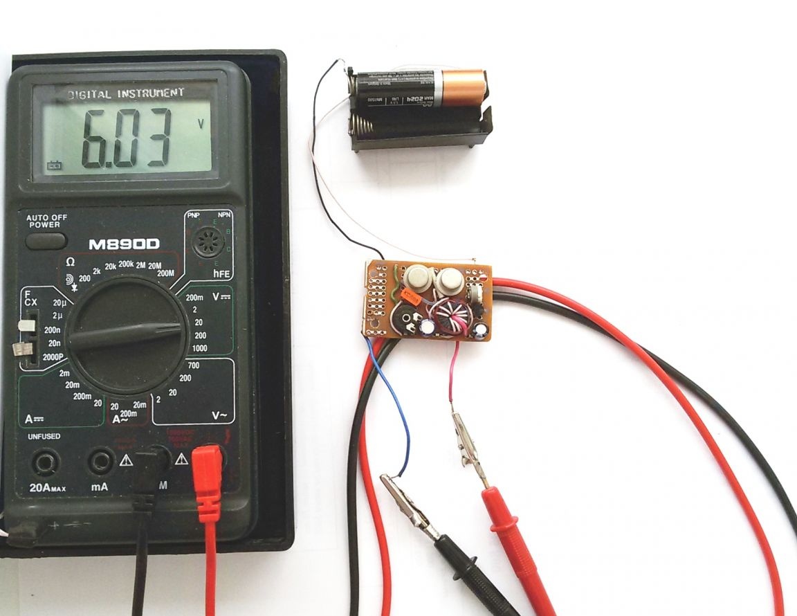
If generation does not occur and there is no voltage at the generator output, check that all coils are connected correctly and swap the ends of one of the T1 transformer coils.


The converter is capable of working even with a decrease in the input voltage of the battery to 1.0 - 1.2 volts.

Photo 14 Battery used during testing.


6.5
8.3
8.5

Add a comment

    • smilesmilesxaxaokdontknowyahoonea
      bossscratchfoolyesyes-yesaggressivesecret
      sorrydancedance2dance3pardonhelpdrinks
      stopfriendsgoodgoodgoodwhistleswoontongue
      smokeclappingcraydeclarederisivedon-t_mentiondownload
      heatirefullaugh1mdameetingmoskingnegative
      not_ipopcornpunishreadscarescaressearch
      tauntthank_youthisto_clueumnikacuteagree
      badbeeeblack_eyeblum3blushboastboredom
      censoredpleasantrysecret2threatenvictoryyusun_bespectacled
      shokrespektlolprevedwelcomekrutoyya_za
      ya_dobryihelperne_huliganne_othodifludbanclose
18 comments
Guest Aleks
this is a very bad rule, it’s right if 10 times it didn’t work out - continue by 11
Yeah, especially if you conceived a completely useless, cheap penny-made homework, perseverance worthy of a better application! I am talking exclusively about this particular home-made! smile
Guest Aleks
Quote: MNS1961
but do not forget the rule - "Do not know how to do it yourself - buy."

this is a very bad rule, it will be right if 10 times it didn’t work out - continue on 11 it will work out.
Critic
Video of the radio from the pulse converter to the studio. I fed the radio from the pulsed power source through the bank, so the bank could not suppress harmonics, and the receiver howled well when receiving. I put the transformer at 50 Hz, the receiver worked fine.
Quote: Ivan_Pokhmelev
Quote: BENDER39
nifiga he does not give 9 v from one, only from three
I do not see any obstacles in the operation of the oscillator from one element. If it does not work, then the transformer parameters simply do not match either by winding or by core material.

Well, the fic knows from the old motherboard
Quote: BENDER39
nifiga he does not give 9 v from one, only from three
I do not see any obstacles in the operation of the oscillator from one element. If it does not work, then the transformer parameters simply do not match either by winding or by core material.
It would be normal if instead of the crown it could be used with a finger-type battery, but it doesn’t give out 9v from one, only from three
Well, perhaps the point here, and indeed, is not "calculated", but "consumer": smirk:

Seachala was: "I bought 4 batteries ... I put it ... I listened once ... I forgot .... In the winter they froze at the cottage .. In the spring they don’t work ..."

Sachvs: ".... (the same thing, but one battery - it's not so bad to throw it away ...))))) ....

In addition, the efficiency is almost compensated (or fully compensated) by the fact that, thanks to the inverter, you can more "drain" the battery more)))))

PS: ... But I would still stuff cheap ...
Quote: Ivan_Pokhmelev
Quote: Valery
"standard set" of batteries lasts for 3 years
If four elements are enough for 3 years, then, taking into account the efficiency, it turns out that you need to change the elements 8 times more often, that is, 3 elements per year. And where is the benefit?
Of course there is no benefit, or rather, not benefit, but rational use. I suspect that the TS decided, if there are such devices, then why not use it in the power of the radio. At the same time, without calculating and analyzing the usefulness of their product. Any converter has internal losses and this must be taken into account. In this design, this is not the right decision.
Quote: Valery
"standard set" of batteries lasts for 3 years
If four elements are enough for 3 years, then, taking into account the efficiency, it turns out that you need to change the elements 8 times more often, that is, 3 elements per year. And where is the benefit?
Quote: MNS1961
but do not forget the rule - "Do not know how to do it yourself - buy."


Well ... Here I do not quite agree with you ... The author is ABLE to do. The question is different - FOR WHAT?
The author wrote to me in PM (why in PM ???) that the "standard set" of batteries lasts for a receiver for 3 years (It is not used as a tape recorder. Only a receiver). Accordingly, if you consider that it is not used in winter, then you should not pack the entire compartment, because the batteries are more likely to "die of old age" than they will be used for their intended purpose ..
... Perhaps this is the answer to your question.

I myself can’t say anything on this issue, because I am not a supporter of “extraneous background noise” during work or leisure. ))))). The receiver is only listening while driving in a car.
But I would solve this question differently - since I do not need a strong current, I would not buy alkaline batteries, and even more so, the expensive Duracel, as in the photo, which is needed only for energy-intensive devices. I would equip the receiver with a set of cheap, weak “Chinese”, at the price of one “Durasel” and that’s it! : laughing:

In general, I have not bought any batteries for a long time - I use rechargeable ones. I bought with Ali both "cheap" and "serious" (for the camera) ....
Quote: Pronin
The converter can also be useful when powered by a solar battery.
What does this have to do with a particular "Low Voltage Power Supply? radio receiver"? No one said that converter devices should not be used for power supply. Only voltage stabilization should be done differently.
I would like to hear from the Author for how many minutes the radio will work with the coolest battery if the efficiency of this device is no more (I would say less) 50%, with which I absolutely agree with Ivan_Pokhmelev (it turns out he’s not such a "Hangover", although with a hangover smart thoughts often arise), as Your device absorbs more energy than it gives off. Did you think you invented the perpetual motion machine? No, I assure you, they haven’t yet decided to make six and a half volts with characteristics 4 times higher than the initial one. Sadly, it is. Your (not yours) circuit is not able to replace four batteries with one.

P.S. You can solve the problem for a few minutes, but aliexpress (for a penny) there are dozens of options for DC DC circuits smaller than yours in size and much more in terms of efficiency.
I do not want to offend you and your work, but do not forget the rule - "Do not know how to do it yourself - buy it."
Quote: Valery
I just really don’t see the point, even if the efficiency is 100%. I always wondered how to INCREASE the battery capacity in mobile devices, and here they suggest reducing it at times, and even doing some body movements for this and incurring some costs.
And here? What for?
Explain, I really do not understand.

1. Your Alkaline, Lithium, and so on are worth the money ... Chinese equivalents in a pack are discharged differently. Those. of 4 elements, 1 dipped and all 4 go for release ... And then they are thrown on the path, into the bushes, in the trash. The young lady will not carry them in her pocket to the point of Reception. She doesn’t have pockets either.blush Chem. components in batteries, especially those crushed by a car, etc., are toxic. And then they are surprised that something is now young men, and already bald (ovate) ...
2. Many devices (fotiki, etc.) do not fully discharge the batteries. Often up to 1.25V, and there were up to 1.35V. The converter (boost) can "suck" the battery to 0.9v
3. The components of this converter are worth a penny
4. The converter can also be useful when powered by a solar battery. 5 elements will give a total of ~ 2v (and here you need 6v)
Only the element base must, of course, be watched by TI and MAXIM
Previously, such devices were used to replace the Krona due to its scarcity and rapid self-discharge. I don’t see any practical meaning here.
I just really don’t see the point, even if the efficiency is 100%. I always wondered how to INCREASE the battery capacity in mobile devices, and here they suggest reducing it at times, and even doing some body movements for this and incurring some costs. I would also understand if this was planned during the design of some small-sized device, and would sacrifice battery life for the sake of reducing size and weight. Then it would be appropriate.
And here? What for?
Explain, I really do not understand.
Why would this efficiency be 80% ?! On VT3, 25% of the output power of the primary converter is lost (its efficiency, maybe, really 80%). On the zener diode circuit, another 10 mA is lost! This is catastrophically a lot. ((
Overall efficiency at best 50%.
As correctly noted Valery, the benefits of the device are slightly less than none.
Sorry, but what's the practical sense?

We advise you to read:

Hand it for the smartphone ...