» Electronics » LEDs »Christmas tree garland with LEDs

Christmas tree garland with LEDs

The Christmas tree garland with LEDs is made on the elements of the K561LA7 microcircuit and creates a light effect of moving or flickering.

On New Year's Eve, it is proposed to make a simple, low-cost LED garland for a small Christmas tree.

The dynamic nature of the operation of the garland does not require expensive and programmable gadgets. The device is unpretentious, economical and reliable in operation, it is instantly mounted on a Christmas tree, and at the end of the New Year holidays, it can be removed without regret to the far shelf until the next case. In addition, the garlands of the device can be used in the form of various lights, small displays and toys with their corresponding arrangement in the form of a propeller, triangle, star, wheel, pointer, “running lights”, etc. So the device can be used to decorate holidays, parties, and with the appropriate design it can become an original gift for a child on his birthday or New Year's Eve.


The proposed device "Christmas tree garland" is made on the basis of a ring generator on the elements of one chip K561LA7 and three transistors. Depending on the location of the garlands, the device creates an original light effect of moving, rotating or flickering chains of lights. The speed of switching garlands can be adjusted. The device diagram is shown in photo 2.

Photo 2 Diagram of a Christmas garland on LEDs. The basis of the device is a ring generator on three elements of the DD1 chip. The fourth element - DD1.4 - is not used and its inputs (pins 12, 13) are connected to the positive power wire. On transistors VT1 - VT3 are made electronic keys, each of which turns on and off one garland of LEDs (respectively HL1-HL3, HL4-HL6 and HL7-HL9). The current through them is limited by resistors R4 - R6. When the generator is operating, pulses of positive polarity are sequentially formed at its outputs.
  • At the moment of the appearance of the pulse at the output of the element DD1.1, the transistor VT1 opens, the resistance of its emitter-collector section decreases sharply and the LEDs HL1 - HL3 flash.
  • Then the pulse appears at the output of the element DD1.3. The VT3 transistor opens and the HL7 - HL9 LEDs light up.
Next, a pulse occurs at the output of DD1.2, the transistor VT2 opens and the LEDs HL4 - HL6 turn on.
  • After which the pulse appears again at the output DD1.1 and the cycles are repeated until the device is turned off.
The garland generator on the DD1 chip, the transistor switches on the VT1 - VT3 and the limiting resistance of the garlands are mounted on a universal circuit board.


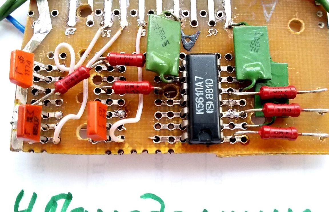
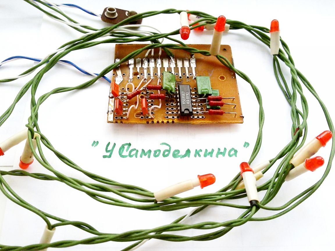
Photo 3 LED garland board. Three dots of 3 to 4 LEDs are connected to points A, B, C of the board and the common wire. After turning on the power and turning the device into steady mode, the garlands flash in turn, resulting in the effect of movement of the lights.
Photo 4 Assembly of a garland on LEDs.


All resistors of the device are MLT-0.125 or other small-sized ones, transistors are any of the KT315 series. LEDs must be of the same type and color of illumination, for example, red or green. Instead of the K561LA7 chip, if necessary, you can use the K561LE5 chip. When applying the top of the tree, you can install in it a constantly burning fourth garland, similarly connecting it to the point "G". When using 4 LEDs in a garland, the limiting resistance R4 - R6 can be eliminated.
Photo 5 General view of the garland on the LEDs.

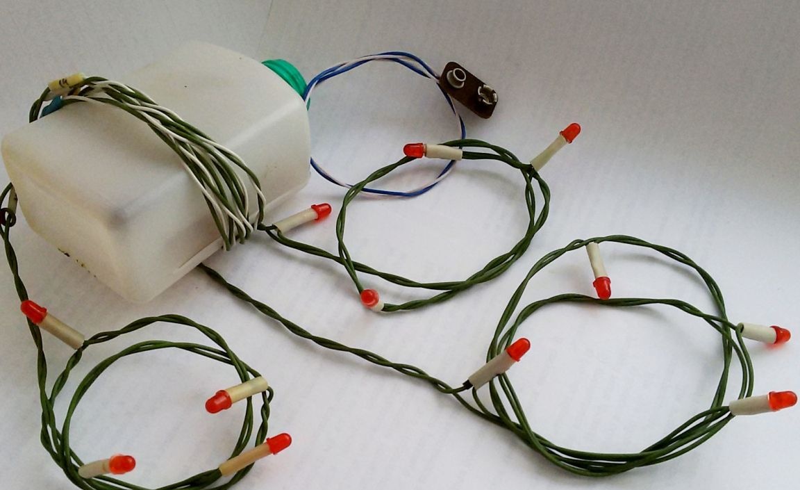
To power the device, you can use a battery of size 6F22 ("Krona") with a voltage of 9V, which is connected to the board through the XI mating connector from the used Krona, eliminating its connection in the wrong polarity. The device can also be powered from any adapter or network power supply with an output voltage of 9 - 12 V, capable of delivering a current of at least 100 mA to the load. For reasons of electrical safety, it must include an isolation transformer (i.e., there is no galvanic connection to the 220 V network). An output voltage stabilizer is optional. For ease of use of the device, it is advisable to place the electronic board (together with the battery) in a small plastic case. When using a battery, install a power switch on one of its walls. With serviceable details and the absence of errors in installation, the garland starts working immediately after turning on the power and does not require adjustment.

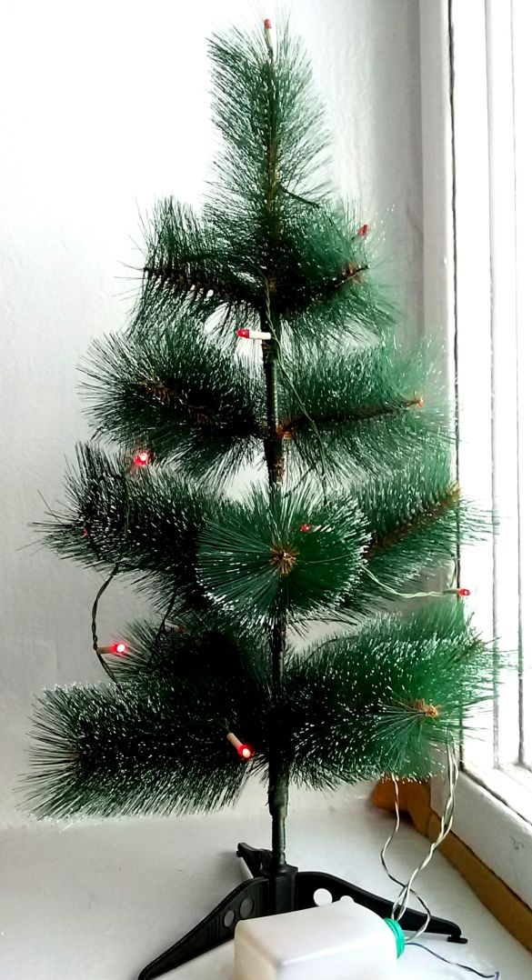
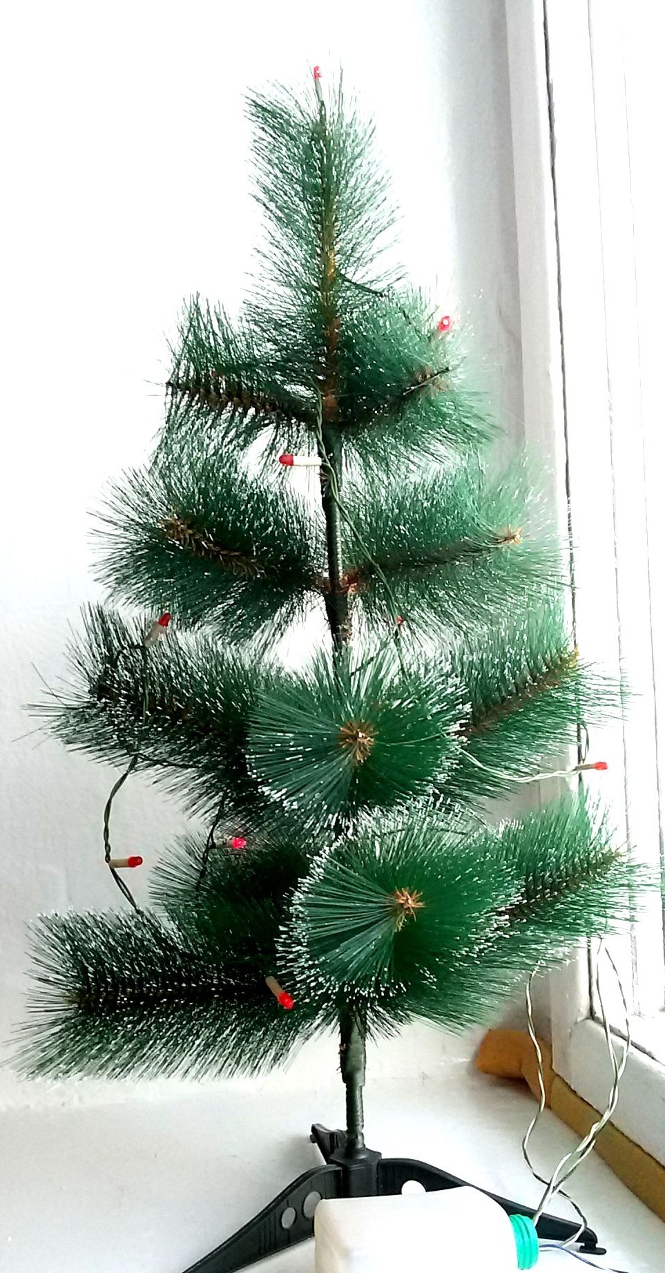
Photo 6 Work of a garland on light-emitting diodes.
9
10
9

Add a comment

    • smilesmilesxaxaokdontknowyahoonea
      bossscratchfoolyesyes-yesaggressivesecret
      sorrydancedance2dance3pardonhelpdrinks
      stopfriendsgoodgoodgoodwhistleswoontongue
      smokeclappingcraydeclarederisivedon-t_mentiondownload
      heatirefullaugh1mdameetingmoskingnegative
      not_ipopcornpunishreadscarescaressearch
      tauntthank_youthisto_clueumnikacuteagree
      badbeeeblack_eyeblum3blushboastboredom
      censoredpleasantrysecret2threatenvictoryyusun_bespectacled
      shokrespektlolprevedwelcomekrutoyya_za
      ya_dobryihelperne_huliganne_othodifludbanclose
9 comments
And in the beginning of the 80s I did "running fire"! Textolite "charted" into 6 sectors. In the center, through a planetary gear from fine-tuning the scale of some device, a “toy” motor was installed (remember, those with two rectangular magnets on the sides?))). He rotated the tin bar, which closed alternately pairs of sectors on the board with sliding contacts! Accordingly, three circuits in the garland were switched on one by one, which I collected from the "remnants" of faulty garlands collected and exchanged from all classmates .... The device itself (and the drive and the garlands) was powered by a six-volt output of the transformer, through which in that era of unstable power networks , surely everyone connected their tube black and white televisions.
... It buzzed and sometimes wedged ...))). But I had a real RUNNING FIRE !!! All terribly envied ....
Quote: lihvin
then everyone will reach for you. And the garland really pleases not for the first year.


blush We are all adults here, do I need it (stretch)? From their own at least fight back.
I’m not telling you that she’s not working ?! And what works is normal (you just didn’t answer what you are feeding the device with). My desktop Christmas tree has been working for 30 years already. It is 35-40 cm tall together with a stand. It rotates, neon bulbs, collector interrupter.Power supply from 220 volts. But this is so yesterday that it’s scary to speak, let alone show.
Author
[quote = To deal] [quote = lihvin] [quote = To deal] This device "looks" like a detector receiver. [/ quote]

I believe that this is an ancient circuit (as a detector receiver) and not 2006 anymore. And about the chip a separate song. And there are already more simplified options, especially since you have not yet fully completed and this craft is solved.
And my magnets and boxes (by the way, modern, and not from old speakers) to which side are being sculpted here? Breathe smoothly, criticism has not hurt anyone yet. [/ Quote]

“Criticism has not hurt anyone yet.” Such criticism harms anyone, even offended you.
And you try constructive criticism. Teach the stupid! Instead of “Seeing Better,” give a reference to the best option and then everything will reach you.
And the garland really pleases not for the first year.
Quote: lihvin
Quote: To Delusam
This device looks like a detector receiver.


And what does a small tool box or drill magnet “look like”?

Maybe this elementary garland, by the way by the season, will inspire someone to take a soldering iron and do something festive for the house.
Or do you think that buying in an online store, inserting and soldering a Chinese "supercircuit" into a finished board is a super complicated homemade product?

I believe that this is an ancient circuit (as a detector receiver) and not 2006 anymore. And about the chip a separate song. And there are already more simplified options, especially since you have not yet fully completed and this craft is solved.
And my magnets and boxes (by the way, modern, and not from old speakers) to which side are being sculpted here? Breathe smoothly, criticism has not harmed anyone.
Author
Quote: Ivan_Pokhmelev
And it would be nice to give a reference to the source. ;)

Radio No. 11, 12 2006
Author
Quote: To Delusam
This device looks like a detector receiver.


And what does a small tool box or drill magnet “look like”?

Maybe this elementary garland, by the way by the season, will inspire someone to take a soldering iron and do something festive for the house.
Or do you think that buying in an online store, inserting and soldering a Chinese "supercircuit" into a finished board is a super complicated homemade product?
This device looks like a detector receiver.
And it would be nice to give a reference to the source. ;)
Everything is correct, except that the resistance of the resistors R4 ... R6 is 75 Ohms for four LEDs, and for three, approximately 240 Ohms are needed.

We advise you to read:

Hand it for the smartphone ...