» Topics » DIY ideas »Simple converter with 12 DC to 220AC 50Hz

Simple converter with 12 DC to 220AC 50Hz

I collected this homemade in order to be able to use power tools and other equipment away from the mains. The homemade product is called "A simple converter with 12 to 220V 50 Hz"


For the manufacture we need:
1) Two transistors KT315 (you can use any other with NPN conductivity)
2) Four transistors of the Mosfet type. IRFZ44 (you can use more powerful transistors)
3) Transformer with windings:
Primary winding = 220 V
Secondary windings two of 12 V
4) Low power switch
5) Resistors with a face value:
680 ohm 2 pieces
4.7 lump 2 pieces
6.2 Ohm 4 pieces (Can also be used on 10 Ohms)
6) Two electrolytic capacitors with a nominal value of 4.7 MF
7) Aluminum radiators
8) Four insulating gaskets for transistors (Not necessary. If transistors of one arm are on one radiator, and transistors of the other arm are on another radiator. And the radiators are not interconnected)
9) Four bolts with plastic washers (Not necessary. If the transistors of one shoulder are on one radiator, and the transistors of the other shoulder are on another radiator. And the radiators are not interconnected)
10) Jumpers
11) Circuit board.


Scheme.
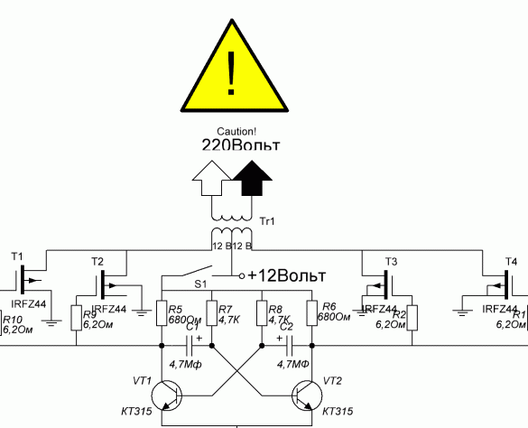
The power of my converter is approximately 1000 watts.
[media = // www.youtube.com/watch?v=G3GpdEUsj6w]
Download PCB https://yadi.sk/d/20siS9CQsawyM
Question \ topic is automatically published in the social. site network - stay tuned for answers there:

Suitable for topic

Related topics

Add a comment

    • smilesmilesxaxaokdontknowyahoonea
      bossscratchfoolyesyes-yesaggressivesecret
      sorrydancedance2dance3pardonhelpdrinks
      stopfriendsgoodgoodgoodwhistleswoontongue
      smokeclappingcraydeclarederisivedon-t_mentiondownload
      heatirefullaugh1mdameetingmoskingnegative
      not_ipopcornpunishreadscarescaressearch
      tauntthank_youthisto_clueumnikacuteagree
      badbeeeblack_eyeblum3blushboastboredom
      censoredpleasantrysecret2threatenvictoryyusun_bespectacled
      shokrespektlolprevedwelcomekrutoyya_za
      ya_dobryihelperne_huliganne_othodifludbanclose
47 comments
So the primary one had to be changed! Think it yourself, 220V to 1000W is <4.5A current. and what section of wire is needed for such parameters? At your TL traffic, a winding of at least 3 times thicker is required (the wire is thicker, not the number of turns).

I will not go further according to the scheme, see for yourself. Is the spouse small? Hence, with the secondary error.
Here is the torus size, I can apply it to the converter.?
They advised replacing the KT315 transistors with the KT815. Capacitors
put film. Can rewind trance, I have tor-iron.
he will go.
I made my converter about 15 years ago, approximately according to this scheme.It worked perfectly and is now alive. Sometimes it still helps. I did it for the radio station, on May 7 we celebrate “radio day” with friends and go on the air in the field, to communicate with colleagues on the “pen”)). A 10-40 W station pulls "quietly." The frequency practically does not change, within 50

Hz
The Chinese sell frequency meters up to 199 Hz.
According to the scheme
1. The calculated data at 50Hz I gave above ...
2. Put 20ohm in the shutter circuit (> 0.5W)
3. Off power supply to the entire circuit (block)
4. To the midpoint of the transformer and the General supply C (capacitor) ~ 2200uF (> 30V)
And by the way, film capacitors today have small internal R. And in this circuit this is not a plus, since it will be necessary to add delays (L, R) so that there is no through current through the keys.
So you can leave electrolytic here. S ~ 2uF. Only more correct with polarity
The best solution would be to use SG3525
They gave you the correct circuit, and in your cartoon frequency of 5 Hz. Check for a short in the arm in which the transistors flew.
So I changed in the circuit, put the film capacitors, replace the transistors.
Yes, in one shoulder field-effect transistors, what is it said?
Quote: Ivan_Pokhmelev
... you can, for example, ceramic, most importantly, non-polar.
Something about ceramic I got excited about. ((Here they will not fit due to the fact that the tank will walk a lot.
Quote: Korneev_Aleksandr
two keys failed.
In one shoulder?
Quote: Korneev_Aleksandr
The circuit included a 100-watt bulb,
It is exceptionally commendable to turn on immediately a large load. ((
Quote: Korneev_Aleksandr
Capacitor C1 and C2 at nominal and voltage which set.?
At face value - as in the diagram Pronin'a, by voltage - any.
So, and replaced the t-ries with KT815 (or similar)?
Film capacitors (type K73-17) for any voltage (> 60V)
Is trans iron tightened (evenly) by nuts?
I did not have time to measure it. The circuit turned on a 100-volt light bulb, it caught fire
the trance buzzed into the floor, two keys failed.
Capacitor C1 and C2 at nominal and voltage which set.?
Winded copper enamel wire 1mm.
Korneev_Aleksandrnot enough. It is necessary to double the diameter, that is, wind your wire with four wires. But at idle, this is uncritical.
Quote: Korneev_Aleksandr
I soldered the circuit, it worked, but something is buzzing trance, the output is a little voltage.
Small is how much? 3 V, 30 V, 100 V ?? Although the measurements on the meander by an ordinary tester are inaccurate, can you measure something about?
Is C3 and C4 equivalent load (input capacitance of two field workers)?
Film capacitors.
It is uncritical, it is possible, for example, ceramic, the main thing is that it is non-polar.
It is necessary to replace the transistors in the multivibrator with a more powerful one ... KT815 and R and C in the base, as in the diagram (analogue of BD137 is indicated in the calculation and C3, C4 do not need to be set). Film capacitors.

Quote: Ivan_Pokhmelev
Ferrite is not suitable here. Wound every 12 V half-winding for each half?

Quote: Korneev_Aleksandr
Wound in the maiden veins checked the output of 12v.
I connected the end of the 1- winding with the beginning of the 2- winding
12v each shoulder.
Winded copper enamel wire 1mm.
Good afternoon. He wound the floor of the winding to each half.
I did phasing in this way, the end of the first half
windings connected to the second. I connect a trance. to the network
I check the output voltage, I get 24v, I check
from the midpoint goes 12v each half.
Perhaps something is wrong. TELL.
And I bought a Chinese on Ali for $ 30.I did not expect something super-duper from him, but he turned out to be "very" ...
I shot a video to show one doubting person. He argued that even at idle, not a single Chinese had pulled a grinder, whatever would have been written on it.
In reality, it is only the Bulgarian that knocks out the protection at the “splash” and when you press it very hard, almost to a stop .... But the protection in it does not need to be turned on after that - just loosen the pressure and it unwinds again ...
[media = https: //www.youtube.com/watch? v = 9fRhvOX5Xcg]
1. What wire did you wind?
2. Check the phasing of switching on the windings.
Ferrite is not suitable here. Wound every 12 V half-winding for each half?
I guess I didn’t connect the trans correctly, in the circuit, as I understand it, maybe not
The primary winding must be connected to the circuit, the output secondary. Links watched
not how I can not figure out a trance. ready trance. no.
There are fierite rings
I’ll try to explain. I wound it in a maiden of the vein, checked the output of 12v.
I connected the end of the 1- winding with the beginning of the 2- winding
12v each shoulder.
Quote: Korneev_Aleksandr
Perhaps that is not so.

But what of you "ticks" have to fish out information?
What's so wrong? What are your calculations? What voltage is each secondary winding? How did you connect the windings with each half?
Did you check the transformer through the network, what did it "give" to you?
Sorry for a mistake. Trans, not film but tape.
Here is the transformer.
There is nothing written on the transformer. I rewound it myself, left the primary
the former Resale shook independently according to calculations. Perhaps that is not so.
Quote: Korneev_Aleksandr
The transformer I have is a SL - film.
What kind of beast is this - film? ;)
That is, 6 + 6? Does he have a type? What is written on it? Are there any letters, numbers on it?
Ivan_Pokhmelev, Transformer step-down 220v to 12v tap from the middle.
Ivan_Pokhmelev- What is your trance?
An instructor in a driving school asks a blonde student - "What is your car?" “Red,” the blonde replied. derisive
Ivan_Pokhmelev, The transformer I have is a SL - film.
What is your trance?
I soldered the circuit, it worked, but something is buzzing trance, the output is a little voltage.
So it’s not Ivan laid out, but SAA6869. Judging by the profile, he was here on March 25 for the last time.
I don’t understand, you laid out everything so well, and demonstrated in the video that the circuit itself is working. Now you write that it does not inspire confidence, explain that with the scheme.
Look for a diagram elsewhere; this article is not trustworthy.
I don’t understand, with a printed circuit board and a circuit, that something does not fit, explain if this is possible.
In this case, the power of the resistors is any.
blush And what am I? I liked the "wires" under a load of 80 A. "Jumpers" is that what and what they "eat" with?
Resistors, it is desirable to indicate the power.
And about the "four bolts" is a separate song.
: disappointed:
I don’t even find fault with a carelessly designed scheme with megafarads.
The power of my converter is approximately 1000 watts.
Watts toeThai "?
At first I wanted to write a remark ... but, looking at the movie ...
Electrolytes incorrectly connected (polarity)
I wanted to see the frequency in Multisim ... but it is not excited at all. Well, right - the resistors in the base are small ... Put 30kom and paper (film) capacitors 0.47mkF. Will be 50Hz

We advise you to read:

Hand it for the smartphone ...