» Electronics »Hidden wiring detector in 5 minutes

Hidden wiring detector in 5 minutes


Let's see the manufacturing process homemade in the video:


Surely many had to hammer a nail into the wall in order to hang some kind of picture, but what if there was a wiring there? So I faced such a problem, how to find the wiring in the wall, so as not to damage it.

Materials and tools:

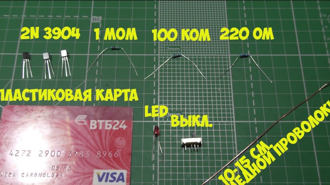
To assemble the detector we need: three diodes marked 2N3904, a resistor with a resistance of 1 MOhm, a resistor with a resistance of 100 kilo-ohms, a resistor with a resistance of 220 Ohms, any plastic card, LED, switch and 10-15 cm of copper wire.
Well, I’ll also add a detector circuit.
Now we bend the base leg back, the emitter leg forward, and the collector leg to the left, and so on with all three transistors, these will be our workpieces.

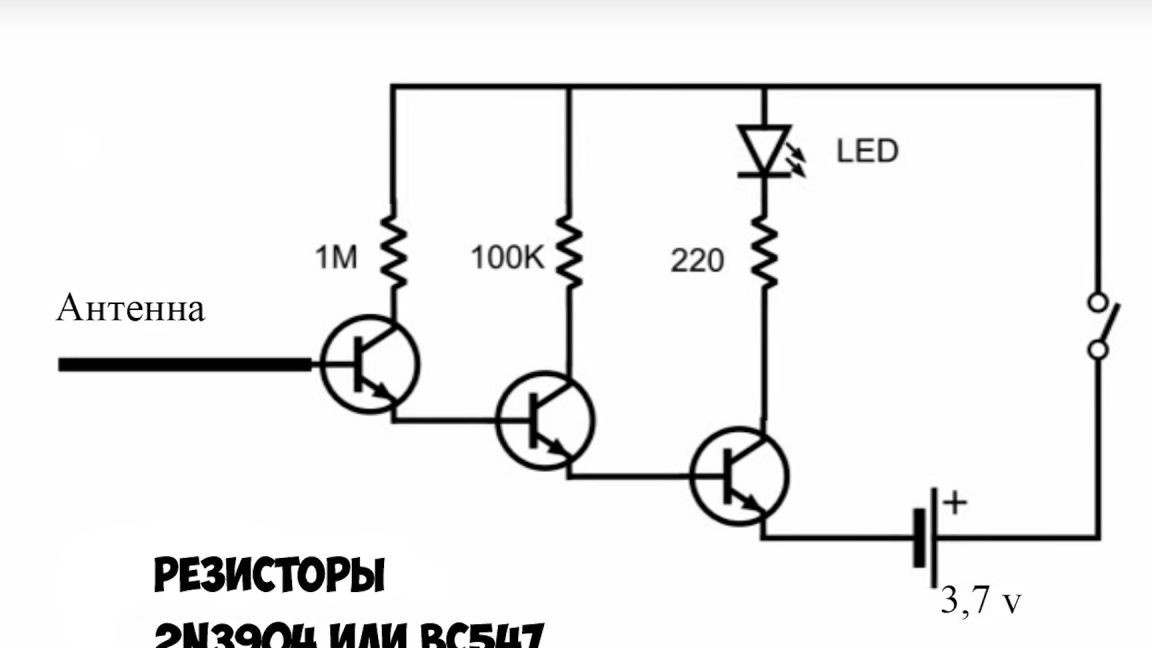
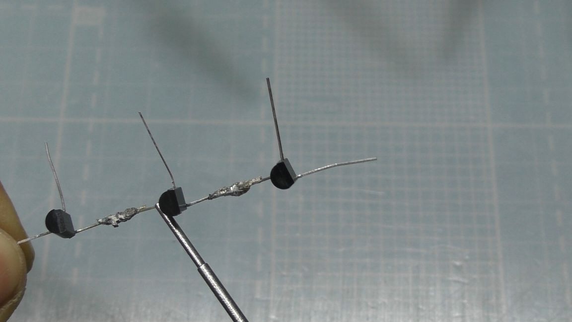
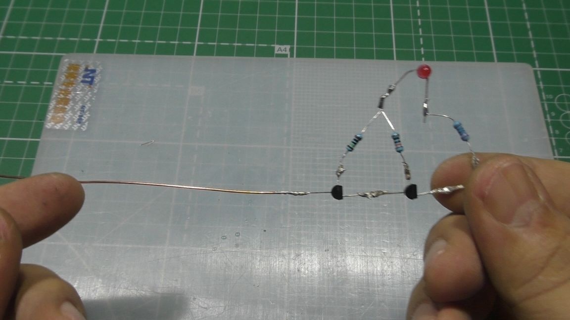
Then it is necessary to solder these three transistors together and the emitter leg should be soldered to the base leg of the next transistor, or more simply, each right leg is soldered to the middle leg of the other transistor. Then we solder to the collector leg of each transistor with a resistor.

After that, we add an LED to our design, as shown in the picture.

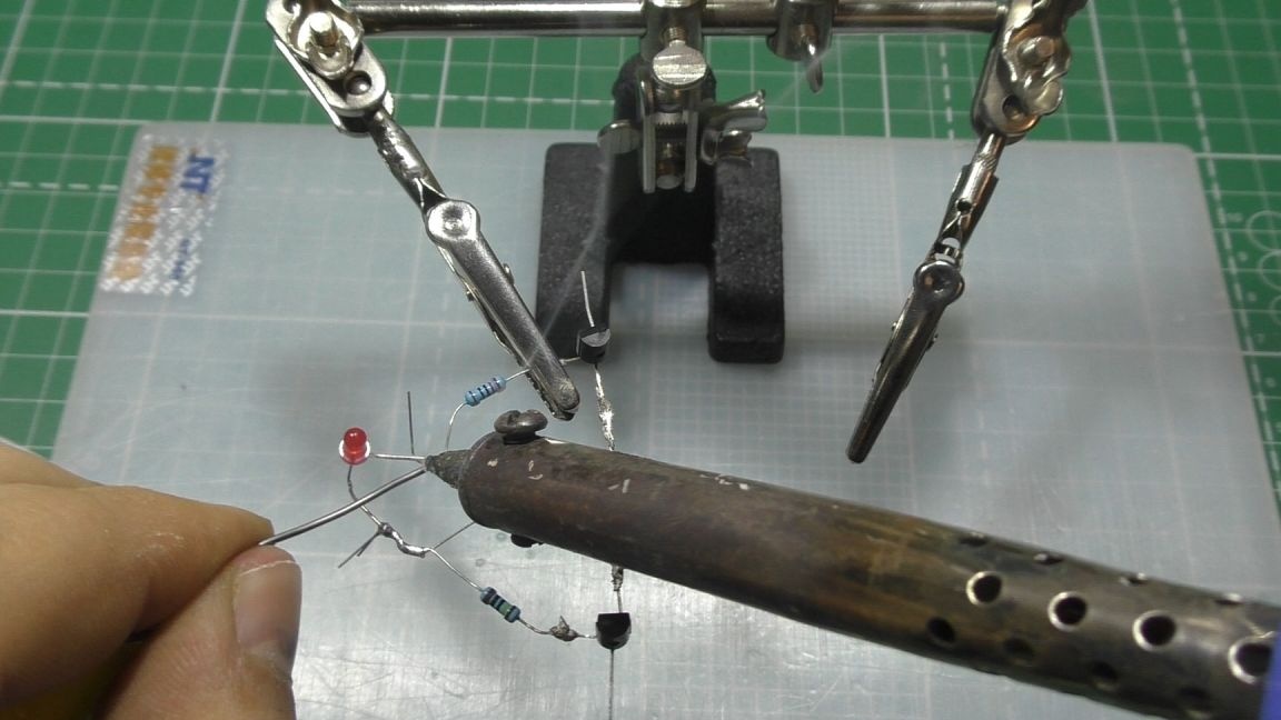
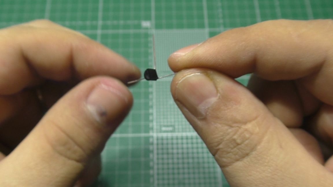
Then, it is necessary to solder the copper wire to the base leg of our first transistor, it will serve as an antenna for us, it should turn out something like this.

Then we take a plastic card and use hot glue to glue our design to the card, also solder the switch, glue the box under the batteries and that's it, our design is ready.

Well, now the test. I will show an example on the wall where hidden wiring goes up from the switch.
While I am leading the device along the line for placing the wire, the LED is on, but as soon as I take it to the side, it goes out. A very useful thing for those who do not know how the cable is laid in the wall.
7.3
6.7
6.9

Add a comment

    • smilesmilesxaxaokdontknowyahoonea
      bossscratchfoolyesyes-yesaggressivesecret
      sorrydancedance2dance3pardonhelpdrinks
      stopfriendsgoodgoodgoodwhistleswoontongue
      smokeclappingcraydeclarederisivedon-t_mentiondownload
      heatirefullaugh1mdameetingmoskingnegative
      not_ipopcornpunishreadscarescaressearch
      tauntthank_youthisto_clueumnikacuteagree
      badbeeeblack_eyeblum3blushboastboredom
      censoredpleasantrysecret2threatenvictoryyusun_bespectacled
      shokrespektlolprevedwelcomekrutoyya_za
      ya_dobryihelperne_huliganne_othodifludbanclose
6 comments
Quote: Pronin
earlier in railway Radio (in the section) a circuit with an input on a field effect transistor with a gate was practiced

So she was already "drawn" here.
The scheme is unsuccessful and Google shows - taken from "Do it yourself do it yourself. "
Repeating it is not worth it, Imho. Earlier in railway Radio (in the section), a circuit with an input on a field effect transistor with a gate was practiced: mask:
Quote: pogranec
And where did you get that "other people's crafts"? Everywhere you scribes seem : laughing:. As far as I understand, he has his own channel on YouTube and he posted a video there and posted an article here.

Rudeness again, and of course you seems can not? Another post by this author and in every blooper. Does this "seem to me" too?
And where did you get that “alien crafts”? Everywhere scribes seem to you: laughing:. As far as I understand, he has his own channel on YouTube and he posted a video there and posted an article here.
The main detail is a plastic card, it will not work without it.
Wherein "any plastic card,".
Please consider this, who decides to repeat.))) blush 
blush
"To build the detector we need: three diodes marked 2N3904, "
Later...
" resistors 2N3904 or BC543 "". So what is it?
And the switch is an extra detail ...
: smirk: oooh! Again, other people's crafts torn off incorrectly.

We advise you to read:

Hand it for the smartphone ...