
Everyone has a different rest in their free time. Someone likes to lie on the couch, someone goes to the gym, and the author of this homemade, based on his needs, abilities and capabilities, he decided to use his free time to create a new universal charger from improvised tools that lay in his workshop.
Materials and tools used to create a universal charger:
housing from a computer power supply
-drill
line
-marker
PDDSKT wire 1.6 mm in diameter
copper wire with a diameter of 2.2 mm
epoxy resin
-voltmeter
printer for printing ammeter scale
transformer from the TS-180 series
thyristor KU202N
thermal paste
a pair of radiators
transistors kt315, kt361
primer for metal
33 kΩ variable resistor
sheet of double-sided fiberglass
-paint
Let us consider in more detail the description of the created device and the stages of its assembly.
The main goal of homemade work was the idea of creating a universal charger, that is, one that could charge almost all the batteries available in the household: from small finger microcadmium batteries to massive automotive lead-acid batteries. Naturally, the idea of such a device is far from new, and there are many different schemes for its creation, one of which the author decided to bring to life on one of his free days.
Thus, it was decided to make a simple but universal charger, the charging current of which can be continuously adjusted from the lowest values to the maximum required at 10A, which will be limited only by the available voltage at the transformer output.
Step one: preparing the device case.

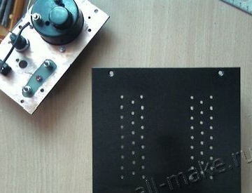
To begin with, the power supply unit was taken from a stationary computer, which, after several alterations, would have to accommodate all the elements of a future charger. It was completely disassembled and all available parts removed. Then the author cleaned it of the existing dirt and figured out how to place the basic elements necessary for a future charger.
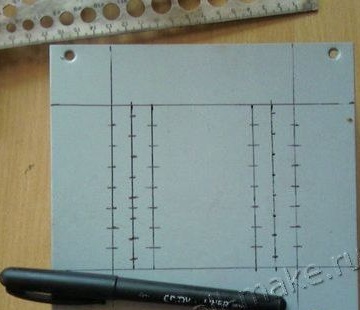
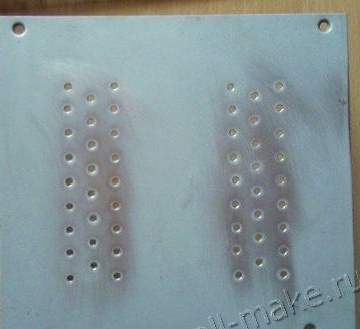
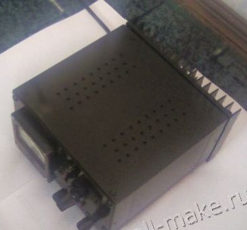
In order for air circulation inside the case to cool the heating elements of the device, it was decided to make several holes on the top of the case. First, for this, markup was made using a ruler and a marker, since the author wanted to achieve the appearance of the factory device, so everything was done as neatly and evenly as possible. After that, two rows of small holes were made using the marking with a drill.
Since the device will be universal, it will have various regulators and a scale with an ammeter, which are best displayed on one front panel of the device. Therefore, with the help of the same drill, as well as files and other tools that were at hand of the author, the front of the case was prepared for the future withdrawal of regulators.
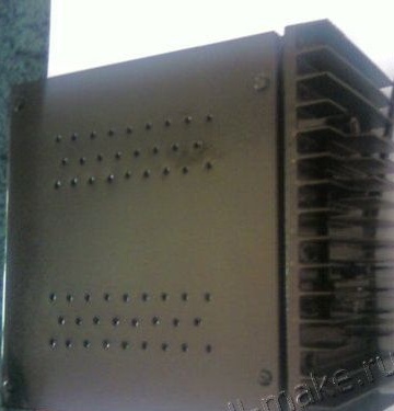
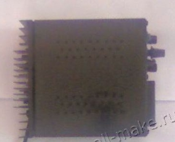
A radiator will be installed on the rear panel, so it has also been modified.
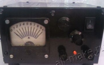
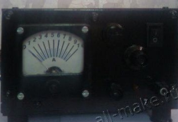
Step two: making an ammeter.
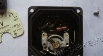
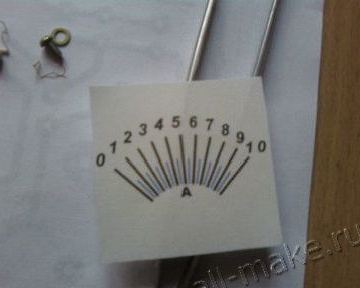
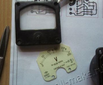
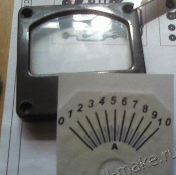


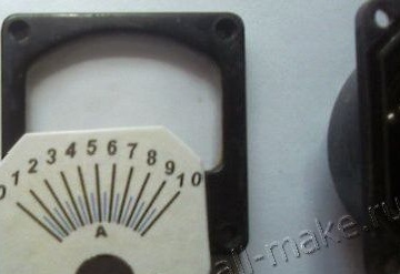
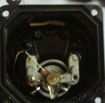
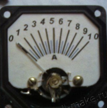
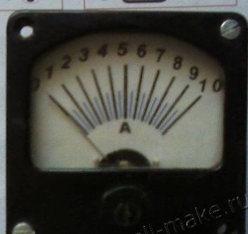
In order to be able to see the readings of the charger, it was decided to connect an ammeter directly to it. But since there was no suitable ammeter among the available stocks, the author decided to make it from an old 250 V voltmeter, since it has a linear scale, therefore, it would be a good fit for this device. During the modification, additional resistors and a rectifier were removed, and the conclusions were simply soldered to the terminals. The scale was drawn in the Front designer program, after which it was printed by a printer and glued to the old scale of the voltmeter.
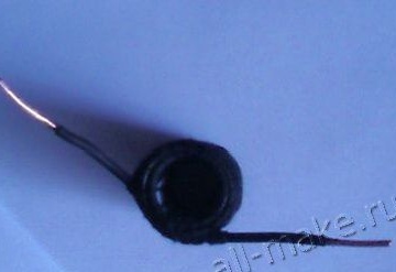
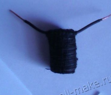
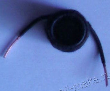
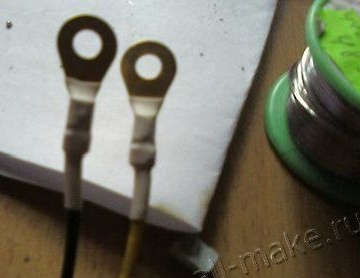
The PDSKT wire found in the workshop was 2.15 m long and 1.6 mm in diameter and was used as a shunt for an ammeter. This wire was wound around the frame, after which it was fixed with threads and filled with epoxy resin, thus reliably fixing the structure. Considering that this is quite enough, and a difference in readings of 5% will not significantly affect the operation of the device, he proceeded to the next stage of creating a charger.
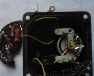
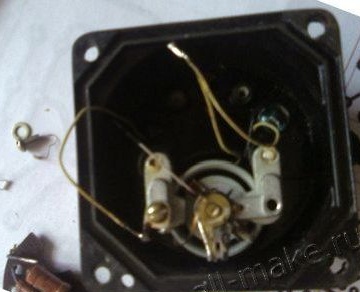
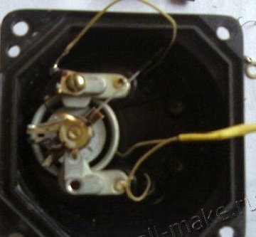
Step three: preparation and placement of the main elements of the charger in the housing.
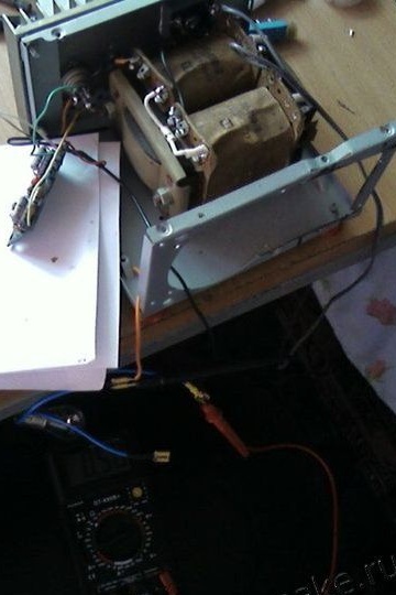
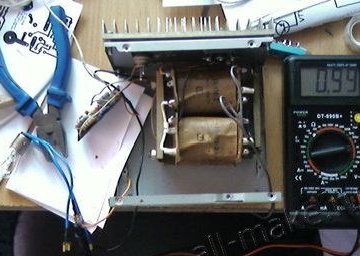
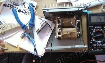
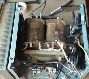
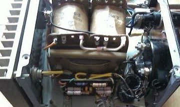
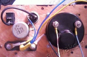
When the preparatory stages were completed, the author proceeded to place the basic elements inside the device. To begin with, he began reworking the existing transformer by 27 V. He was rewound with a copper wire with a diameter of 2.2 mm, although 1.6 mm or a bus with an area of about 4 mm square would have come up. After that, it was placed inside already with 18 V voltage in the secondary winding and with a power of 120 watts or more.
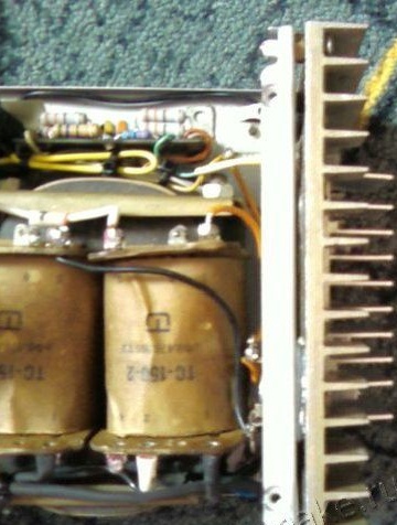
A radiator was installed over the entire area of the rear wall, which consists of two parts connected by a thermal paste. A KU202N thyristor with a capacity of 10 A was attached to this radiator. In addition, a 35 A diode bridge was attached to the same assembled radiator.
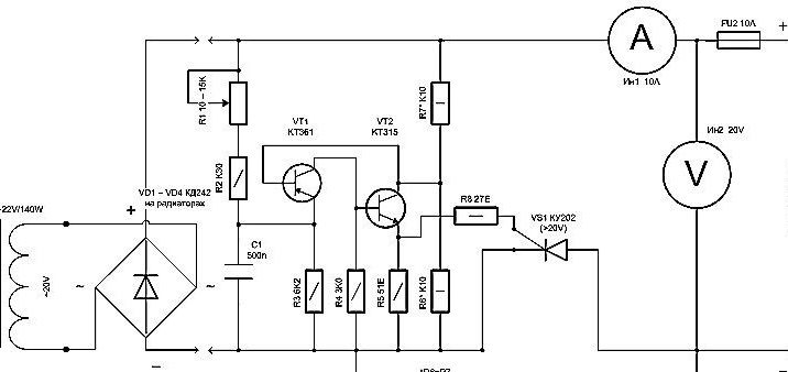
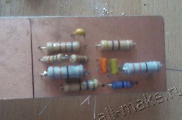
To build the current regulator, the author used a pulse generator assembled from CT-315 and CT-361 transistors, although others with a voltage of 30 V and a gain of more than 100 can be used. An important nuance is that if you take transistors with a large spread, then at small currents can be interrupted generation, so it is better to use both transistors with close gain, but different conductivity.
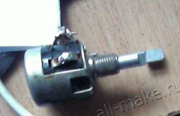
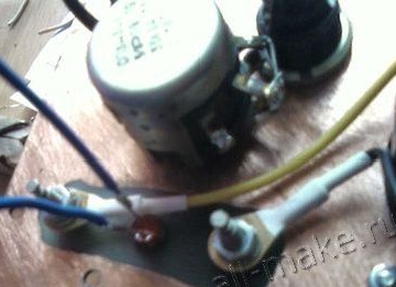
The available dual variable resistor with a resistance of 33 kOhm was also modified to create a charger regulator. To lower the threshold to 0.5 V, the author paralleled the resistor and a resistance value of 16.5 kOhm was obtained, respectively. All this was done for a larger range and, consequently, greater versatility of the resulting charger, so if you only needed to charge car 12V batteries, a 4.7 kΩ variable resistor would have come up, but the author decided to focus on the versatility of the device.
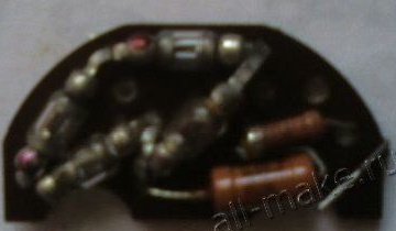
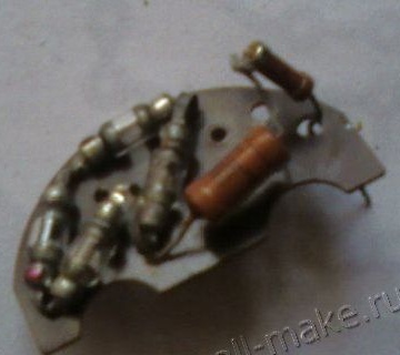
Step Four: Create a Scheme.
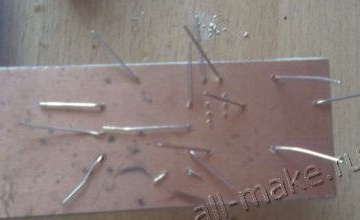
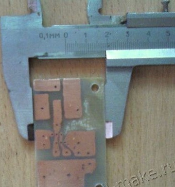
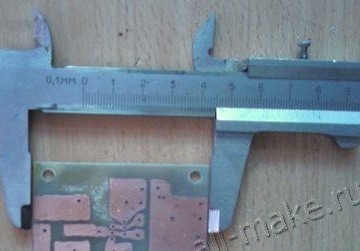
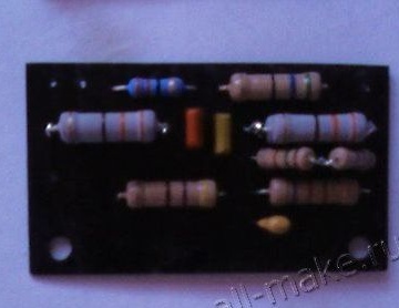
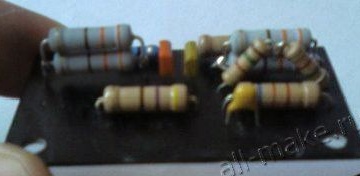
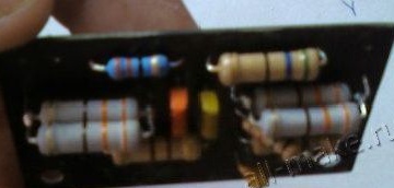
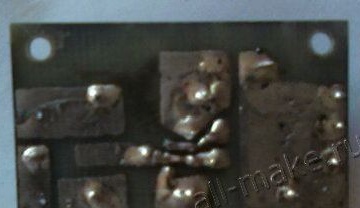
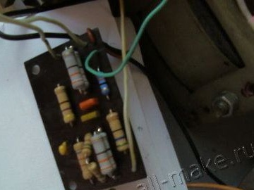
Since the dimensions of the case used are limited, to create the circuit, the author decided to use a printed circuit board, although it can be made with a hinged installation.
The author also made the circuit board for himself from the means that were available. It took about half an hour to etch it, after which it was washed, and the author proceeded to subsequent soldering, tinning and, accordingly, installing it in the device case.
Fifth step: creating a front panel for regulating the charger and painting.
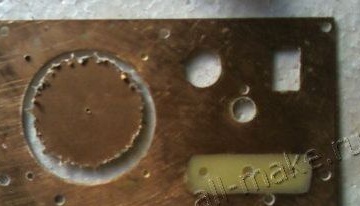
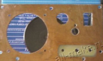
As the material of the front panel, the author chose fiberglass. It was etched on both sides at the terminals. Further, according to the marked markings, holes were cut out for fixing and installing terminal blocks, indicators, regulators, a switch, a fuse, and an ammeter scale.
After that, the resulting panel was attached to the main body with self-tapping screws and all controls were withdrawn and fixed in their corresponding holes.
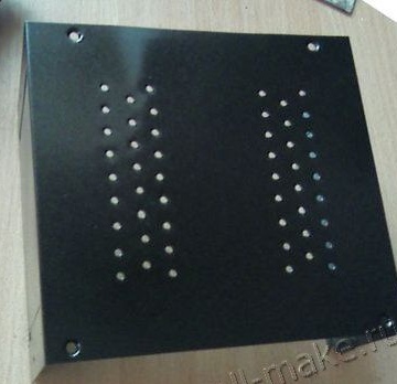
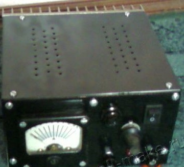
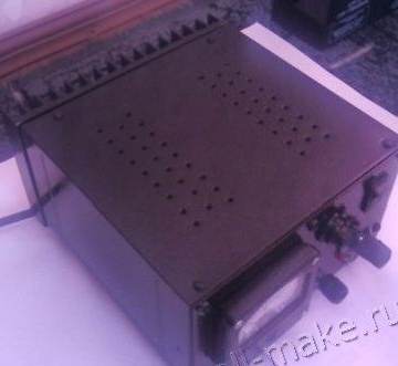
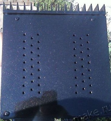
Then, taking the black metallic paint that the author had left after painting the bumper of his car, he used it to paint the entire body of the resulting charger.
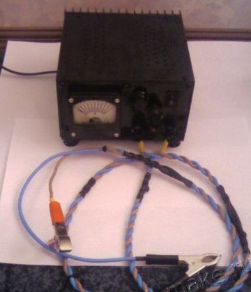
You can see the result in the photographs, the device has a very nice look, and looks like it was assembled at some enterprise, and not in the garage.
Step Six: Test Indications.
The device was turned on at night to charge a 6ST90 battery. The battery was charged for about 12 hours with a charging current of 8A. No breakdowns or malfunctions were detected under such a load. The heating was small, due to the good heat transfer and heat transfer from the radiators, the transformer was not heated very much. From this it follows that this charger is fully functional and reliable.

You can find additional information at the "source" link below, where you can also ask questions to the author of this device.