

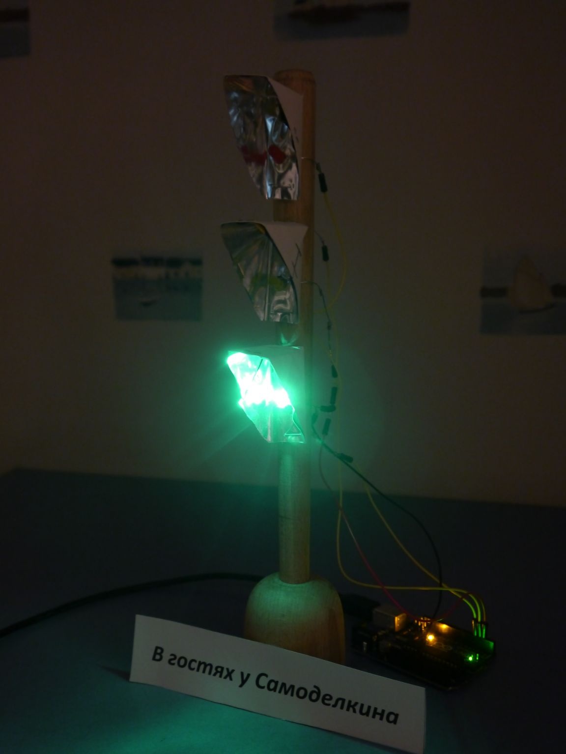
Good day to all)) In this article, I will try to maximally intelligibly talk about how you can do layout of a real traffic light. If your child likes to tinker with cars, it is not so difficult to add reality to the process of his game, as well as to make this activity even more fun, entertaining and interesting! So let's make a traffic light! And so let's go!
What we need from the materials:
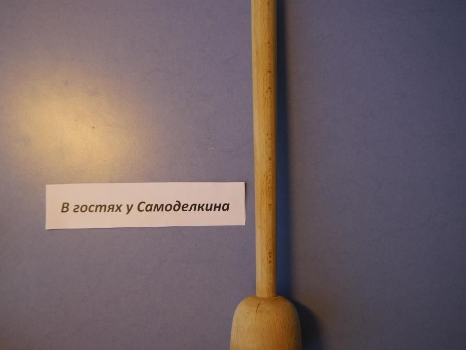
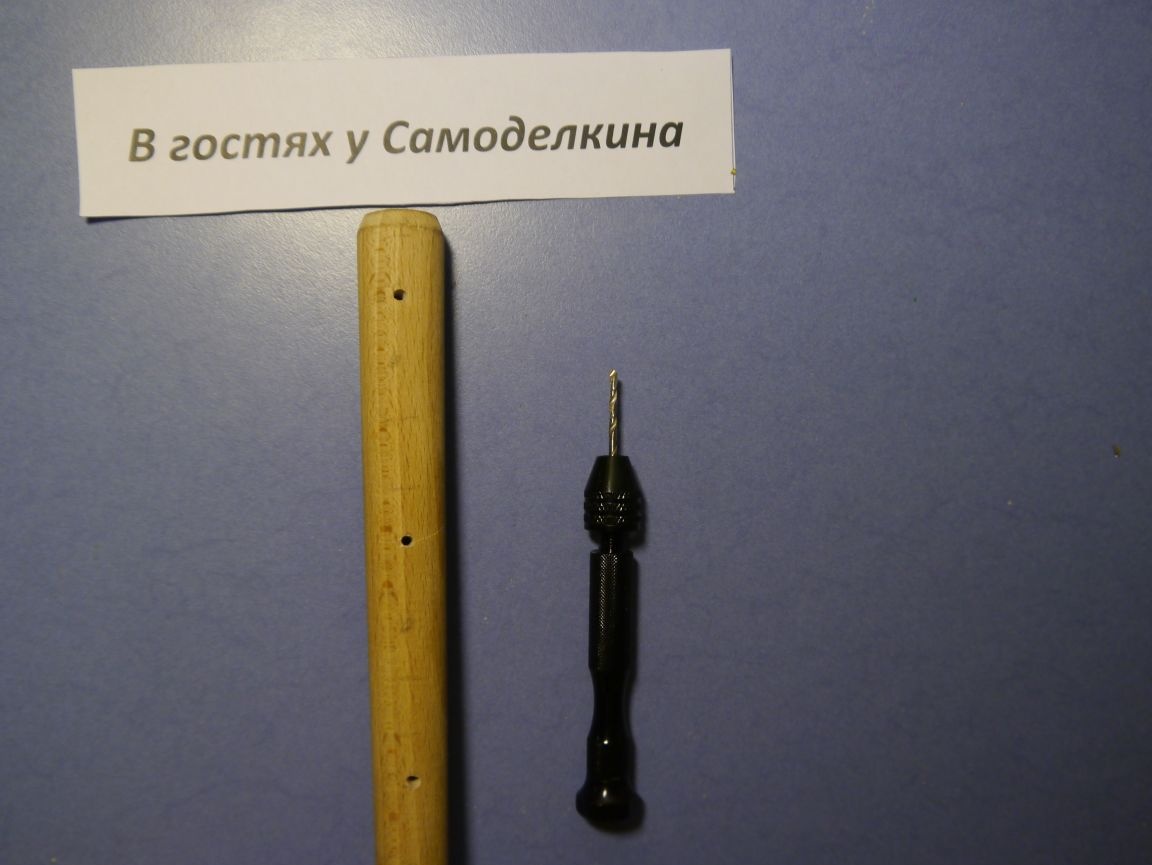
Pusher (we will use as the basis for our invention!)
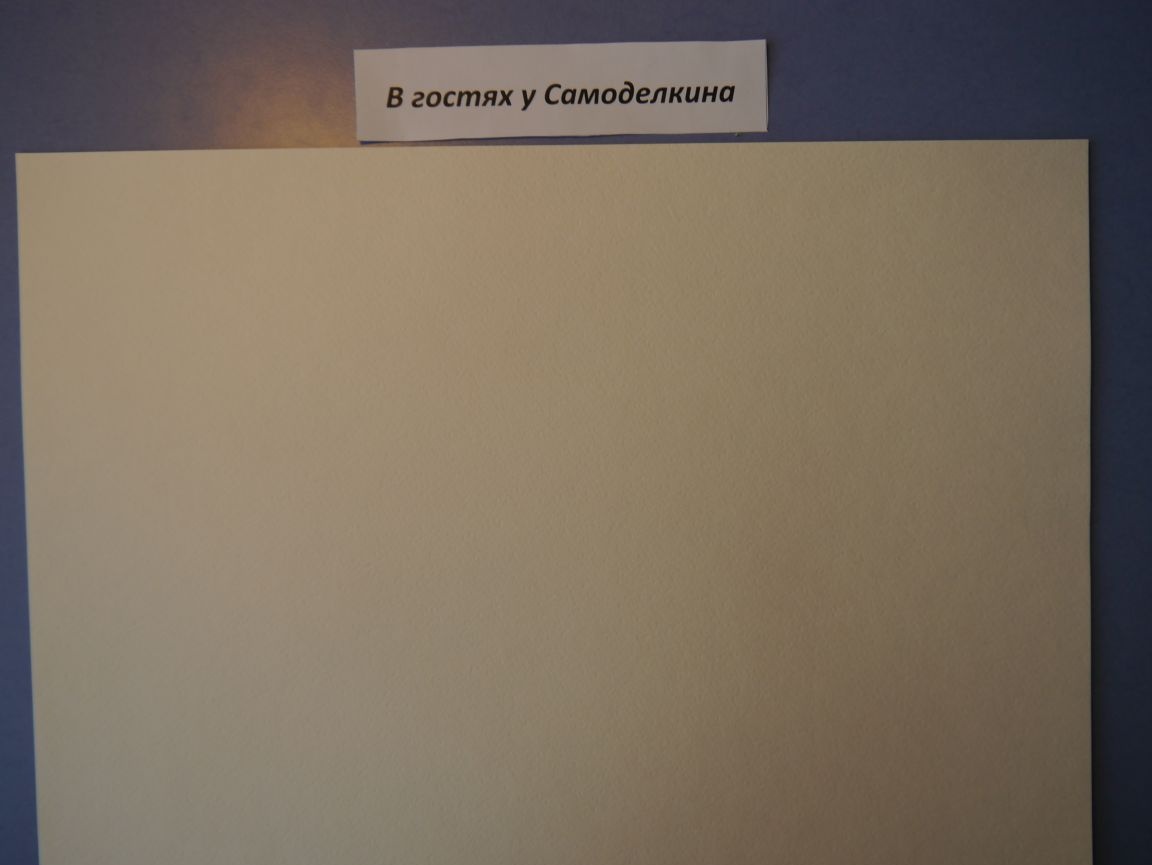
Sheets for watercolor (you can cardboard or any other thicker paper)
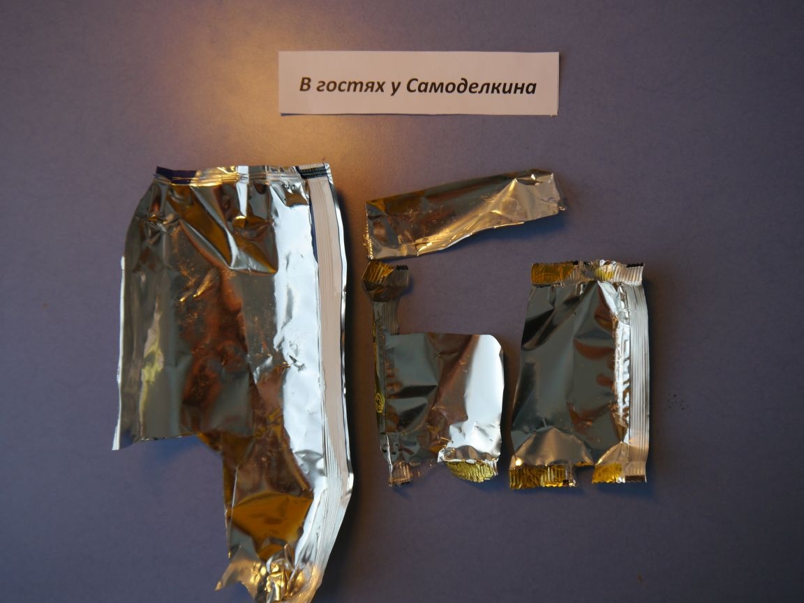
Foil (I took ordinary wrappers from under glazed curds)
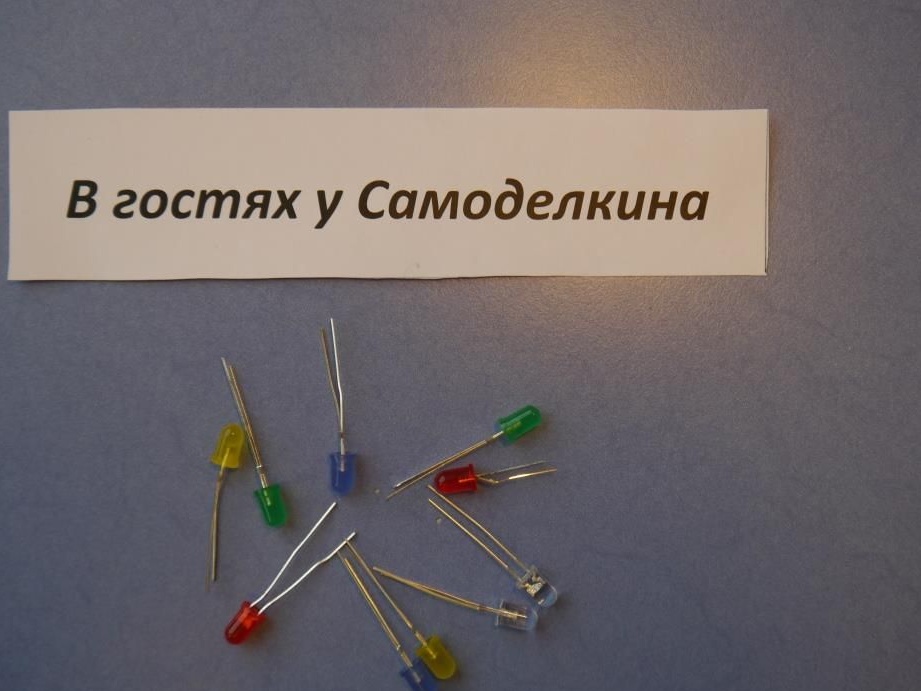
LEDs (three colors: red, yellow, green)
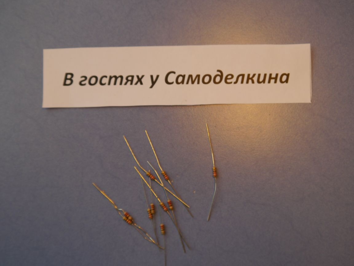
Resistors (Resistance 220 Ohms)
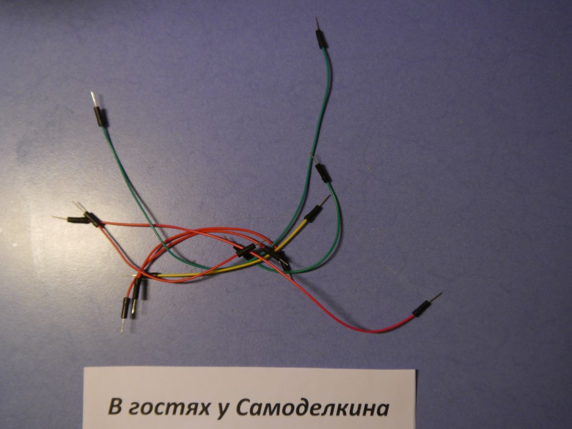
Wires
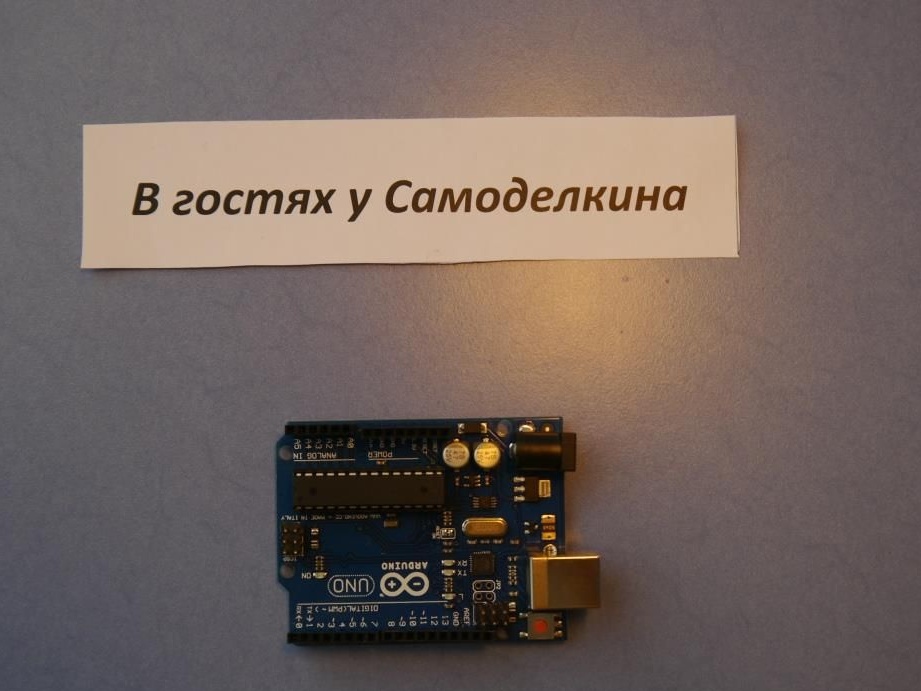
Controller Arduino
From the tools we will use:
Hand drill (with thin drills)
Screwdriver
Screws
Stapler
Knife
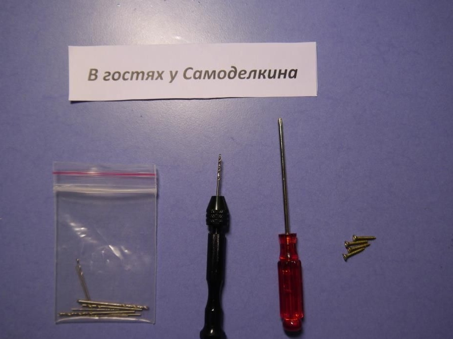
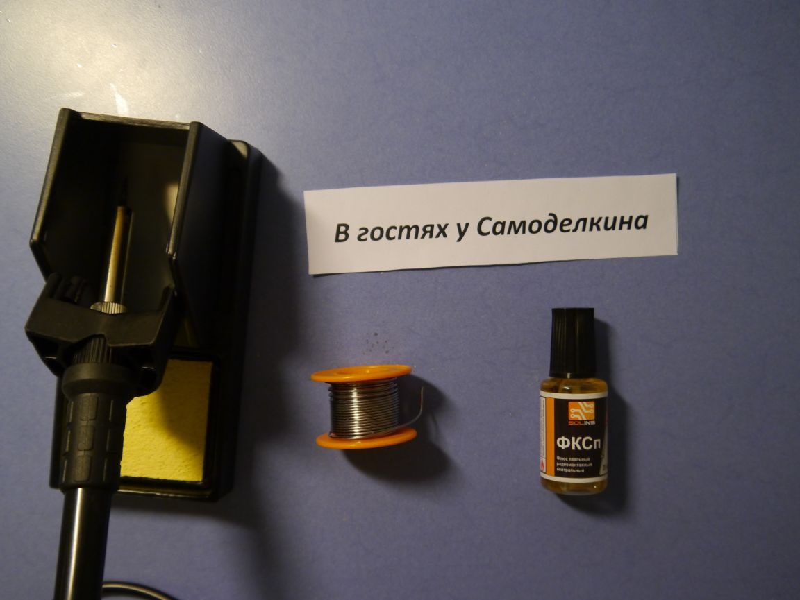
Soldering iron (solder, flux)
In principle, everything, now let's start the process of assembling our layout. Divide everything into 3 big steps ..
Step No. 1 Assembly of "Peaks"
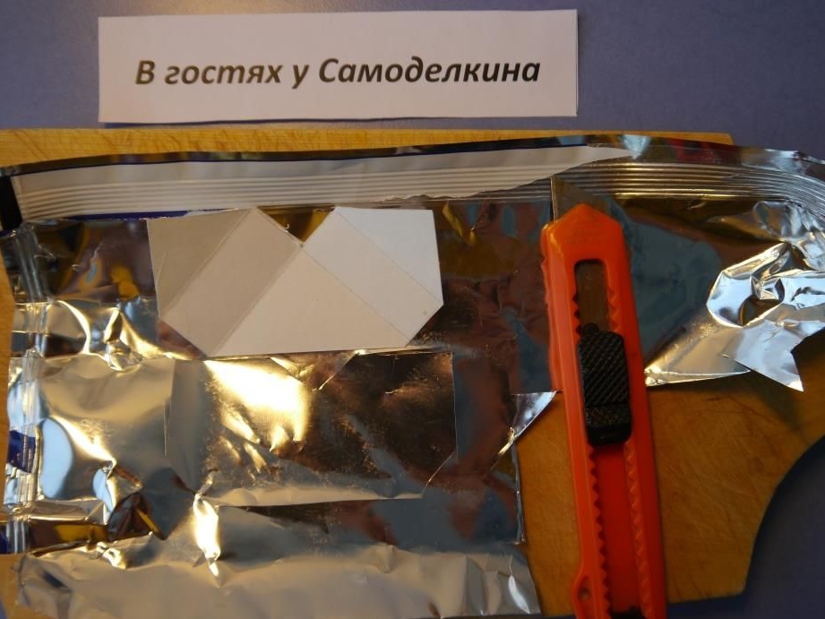
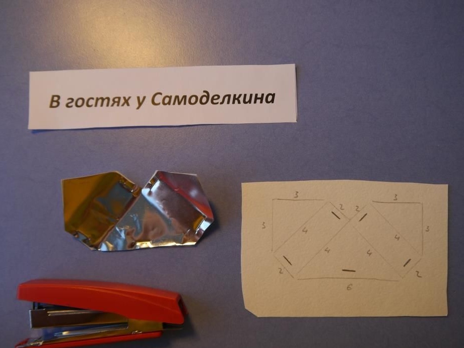
To begin with, we will make visors for traffic lights from paper. We draw with a pencil and cut out with scissors (in the photo the numbers are the length in centimeters).
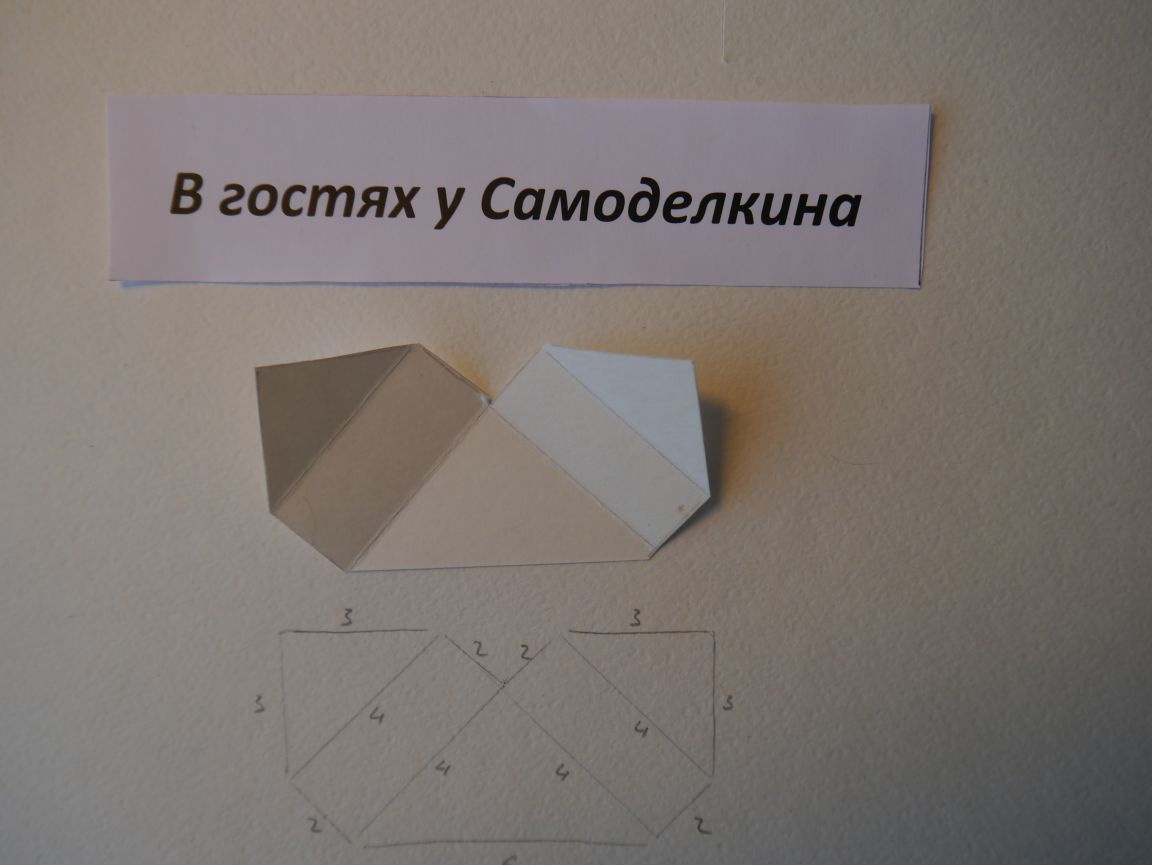
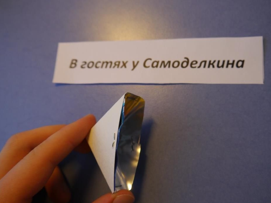
Adding our blank - we get a visor ..
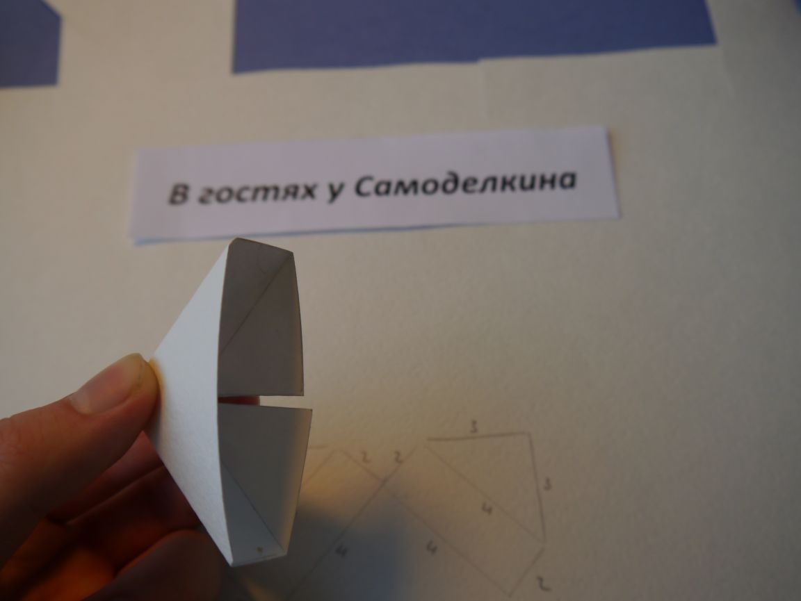
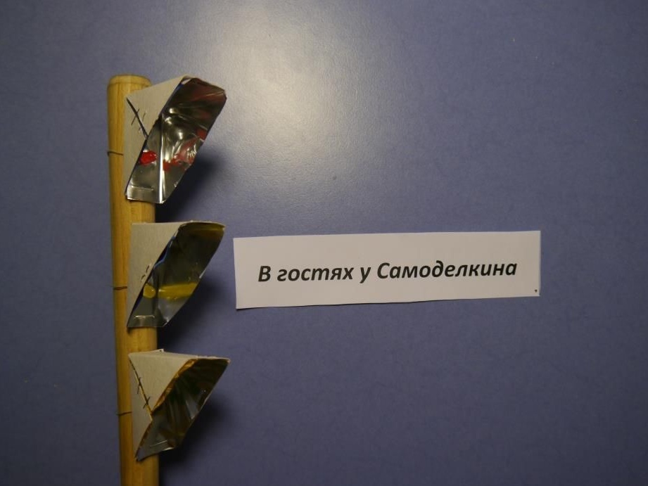
But so that the light emitted by the LEDs is reflected as brightly as possible, a foil should be fixed to the inner surface.
First, cut it out in exactly the same shape as the visor (with a knife), and then fasten both materials together with a regular stapler.
In the photo (below) I showed with black stripes where I fastened ..
After that, we turn our workpiece and fasten the remaining side parts.
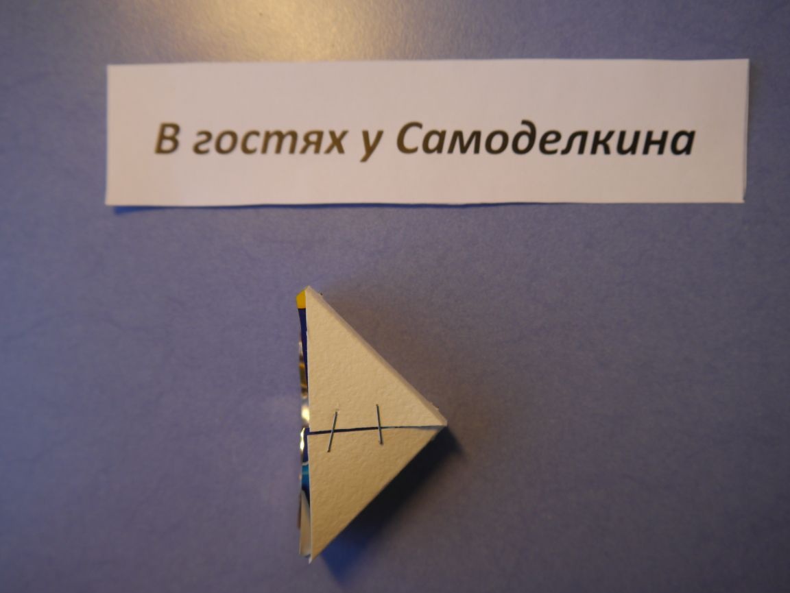
We repeat the whole process three times, because we must have three visors!
Step number 2 Mounting "Visors"
With the help of a drill, we drill holes for our peaks on the pusher.
On the back side of the visor we make two holes: the smaller for the self-tapping screw, the larger for the LED.
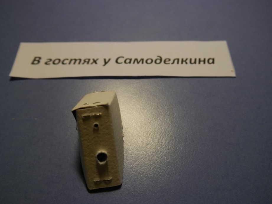
We pass the LEDs on the back side and fasten the visors to the pusher. For now, we simply bend the legs of the LEDs to the sides .. Again, we repeat everything for each visor.
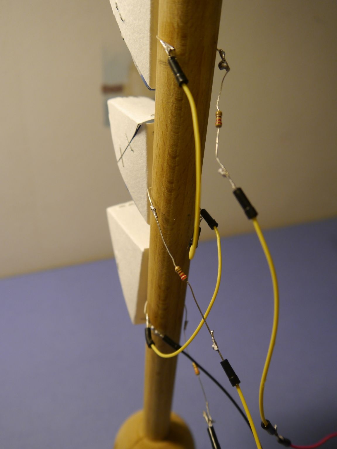
Step 3 "Electronics"
We solder together the cathodes of the LEDs (their earth). Let me remind you that the cathode is a short leg)
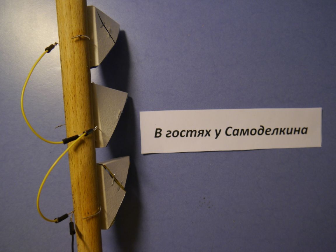
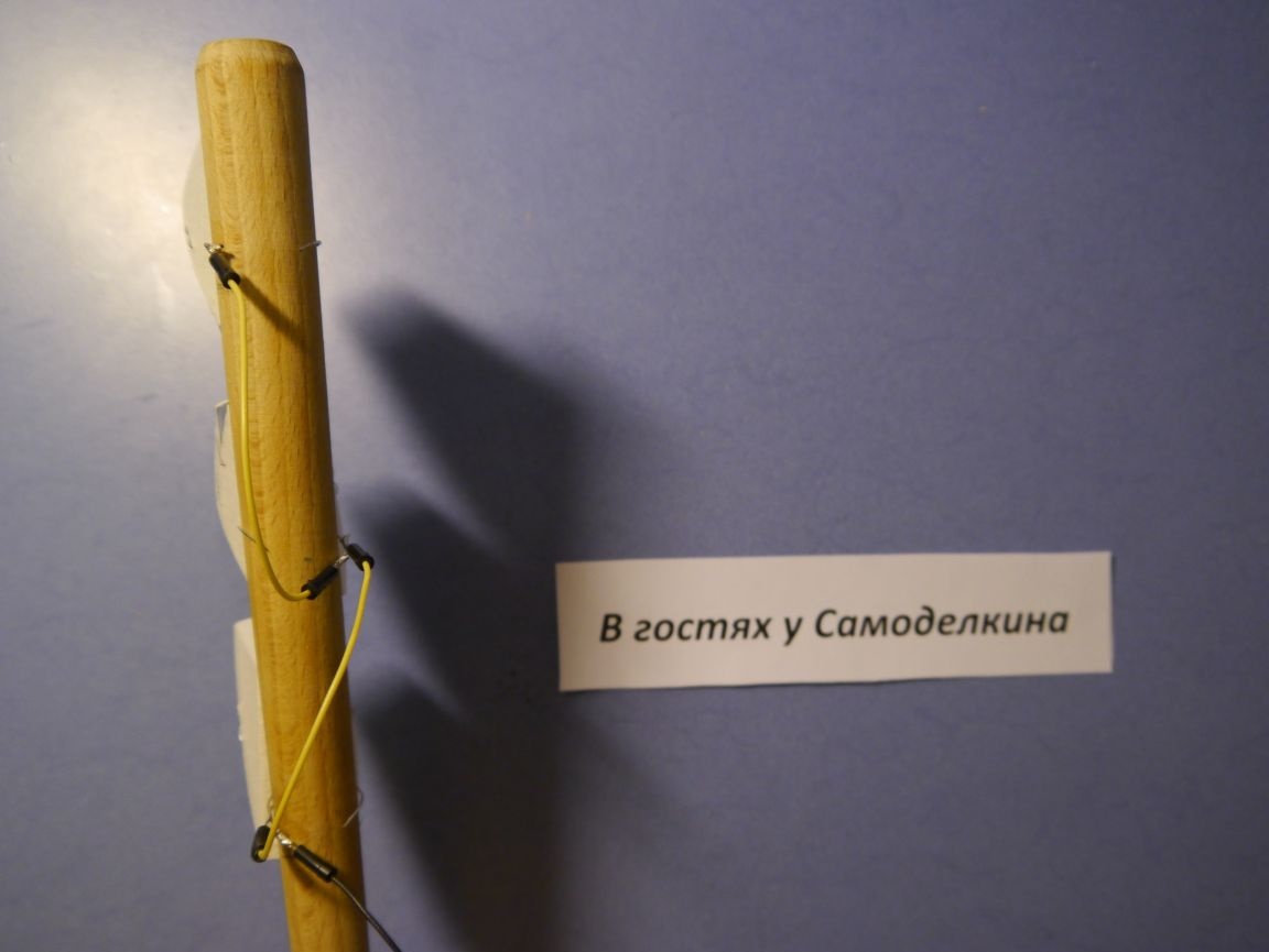
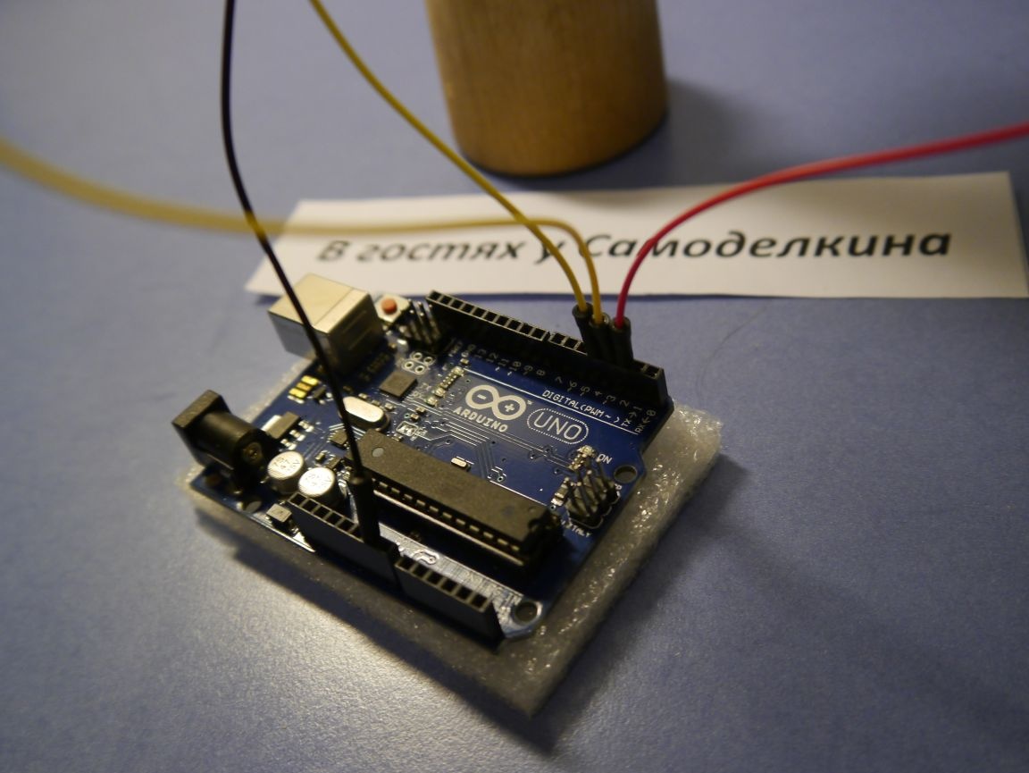
Insert common ground into the GND microcontroller.
Now take the other three wires and solder them with resistors.
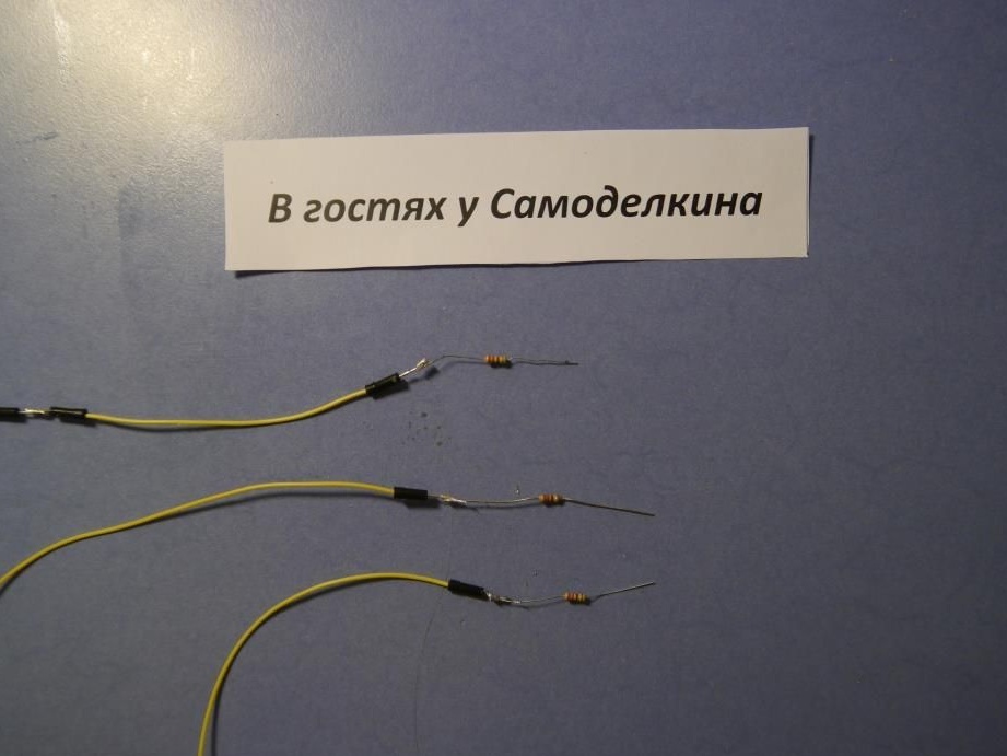
We’ll stick the wires into the contacts of the arduino (I took pins 2, 3, 4), and solder the ends of the resistors to the anodes of the LEDs.
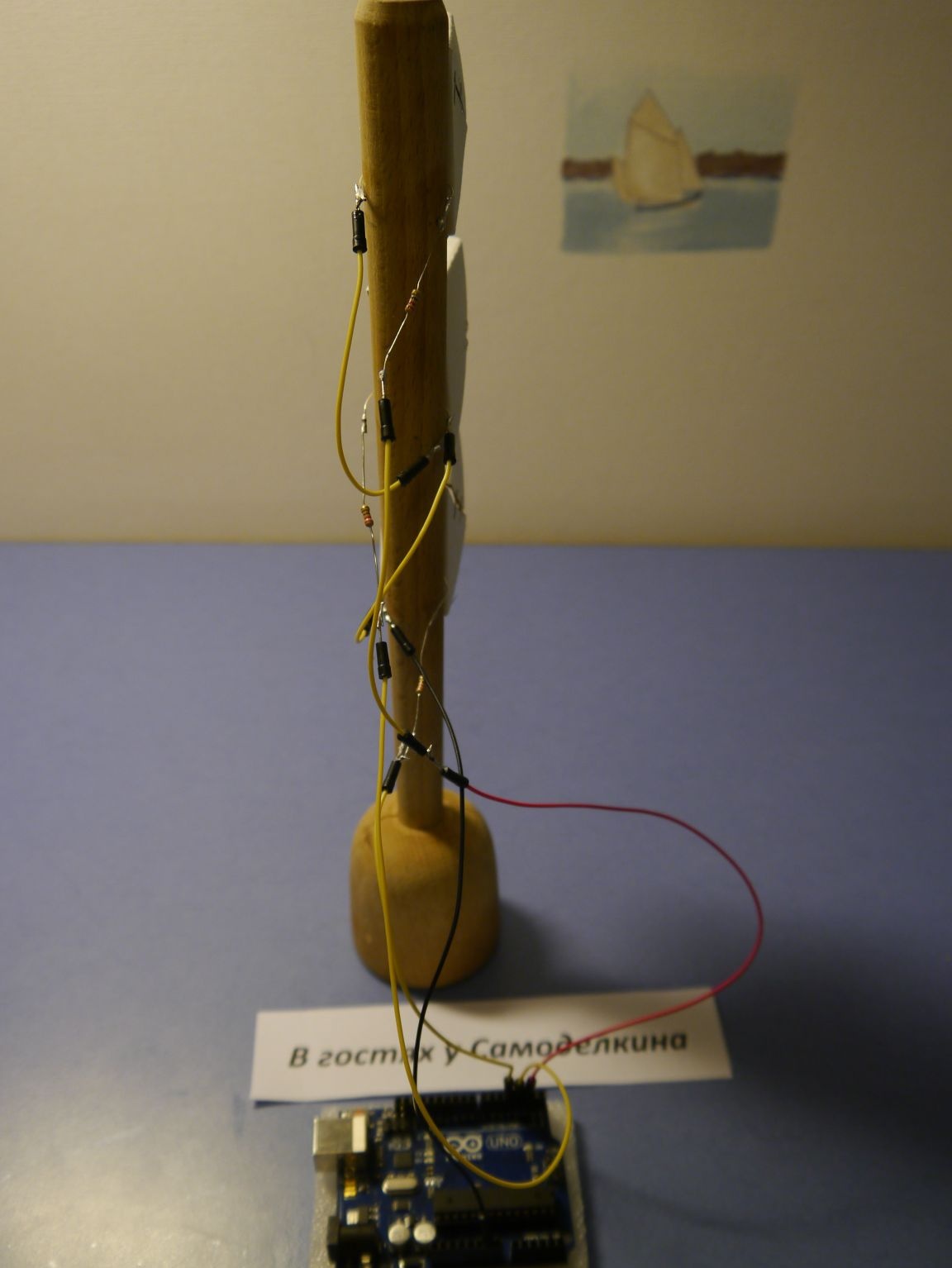
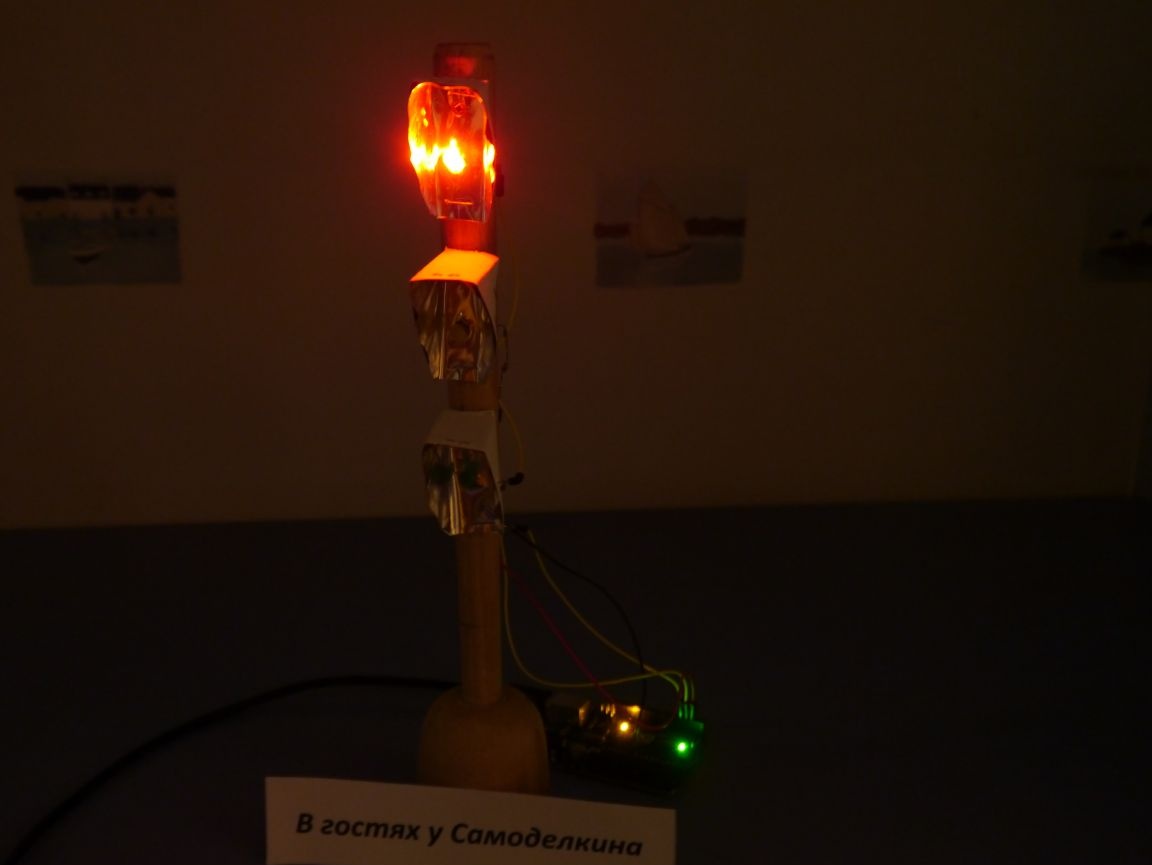
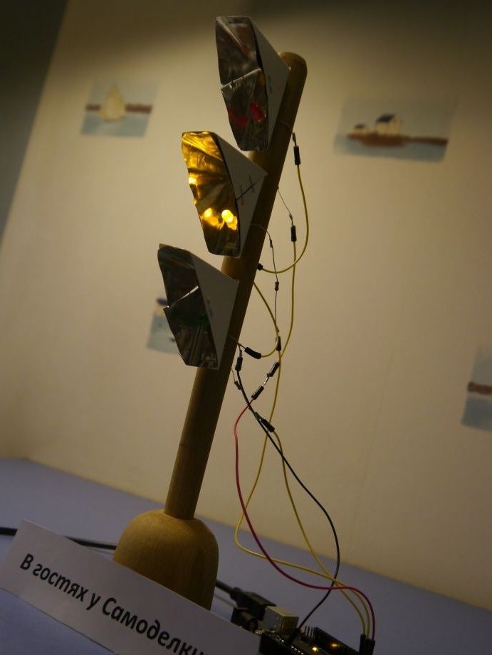
Now it remains to download the next sketch in arduino and delight loved ones with their craft!
boolean k = 0;
void setup ()
{
pinMode (2, OUTPUT);
pinMode (3, OUTPUT);
pinMode (4, OUTPUT);
}
void loop ()
{
digitalWrite (2.1);
digitalWrite (3.0);
digitalWrite (4.0);
delay (3500);
for (int i = 0; i & lt; 6; i ++)
{
  digitalWrite (2, k);
  k =! k;
  delay (800);
}
digitalWrite (2.0);
digitalWrite (3.1);
digitalWrite (4.0);
delay (3500);
for (int i = 0; i & lt; 6; i ++)
{
  digitalWrite (3, k);
  k =! k;
  delay (800);
}
digitalWrite (2.0);
digitalWrite (3.0);
digitalWrite (4.1);
delay (3500);
for (int i = 0; i & lt; 6; i ++)
{
  digitalWrite (4, k);
  k =! k;
  delay (800);
}
}
Change the sketch and set your time for the flashing lights and their delay!
That's all for me, Thanks to everyone who read to the end! I hope this homemade you liked and inspired completely new ideas !! Good luck