

I often make robots or toys based on Arduino or similar boards. As an option for controlling such devices, I use the infrared range. In terms of the receiver there are no problems, it is easy to find and connect, but in the case of the remote control it is more difficult.
And here are two options:
1. use the remote control from the TV or other equipment that is at hand. Then a lot of fuss, problems and a lot of time. First, you need to read the button codes from the remote control, and then write them to your firmware. Another problem is that the remote control sends a signal when the buttons are pressed once, does not repeat it (if the device moves or is far away, the receiver may not read it at a time), and does not send anything when the button is released, which is very inconvenient when it is necessary to control moving machinery. Well, I do not want to control the TV and the machine at the same time.
2. make your own remote.
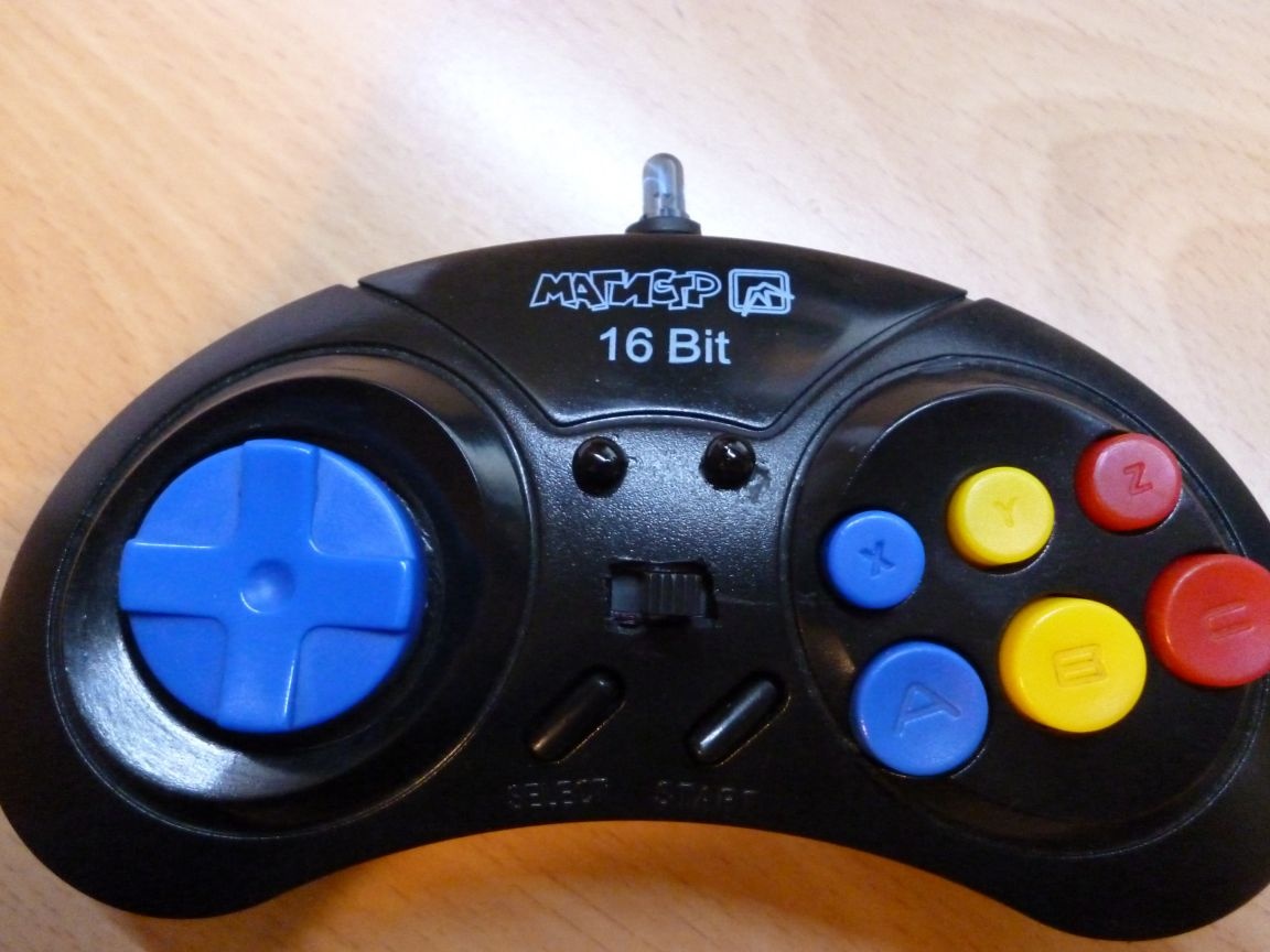
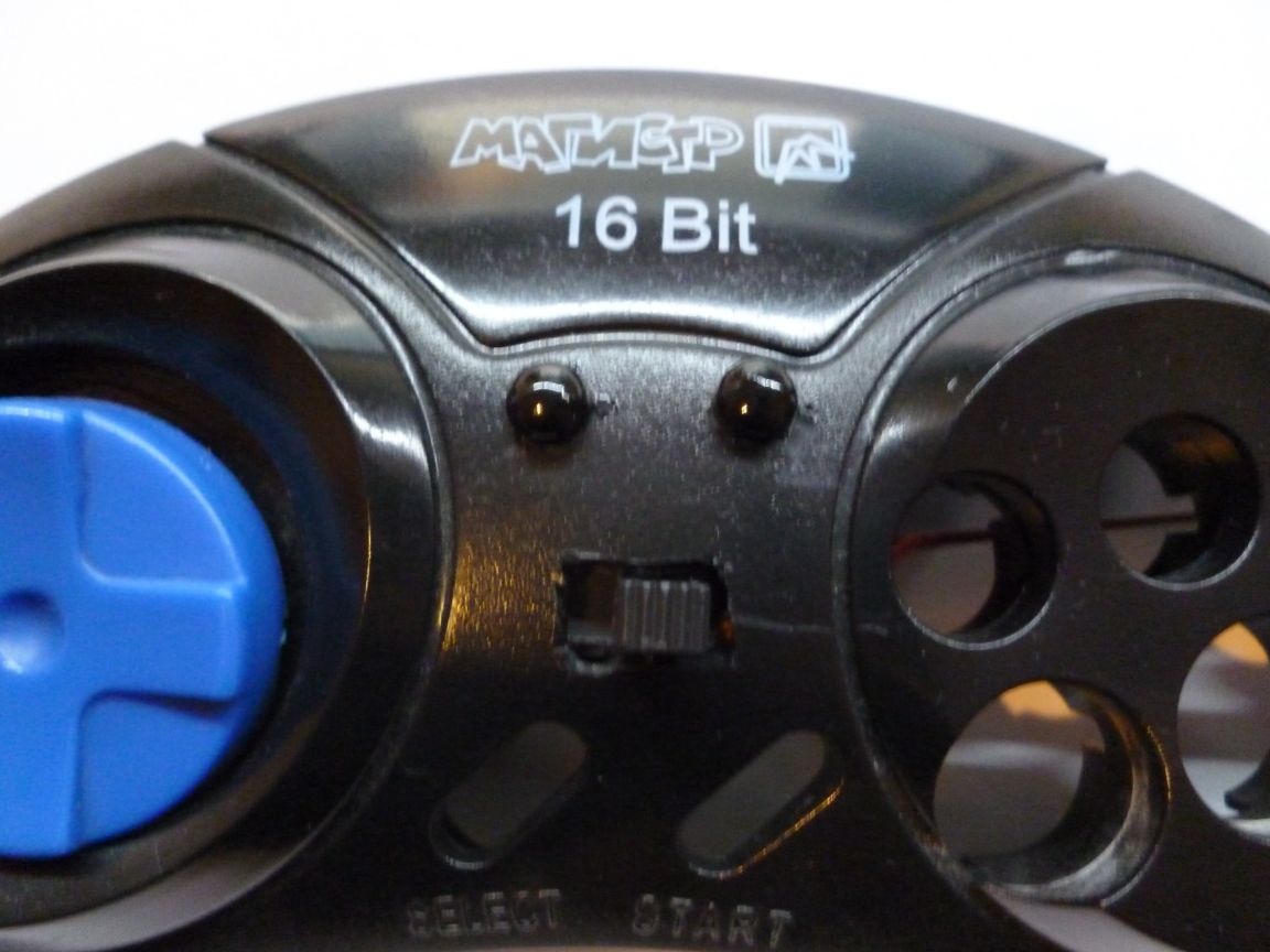
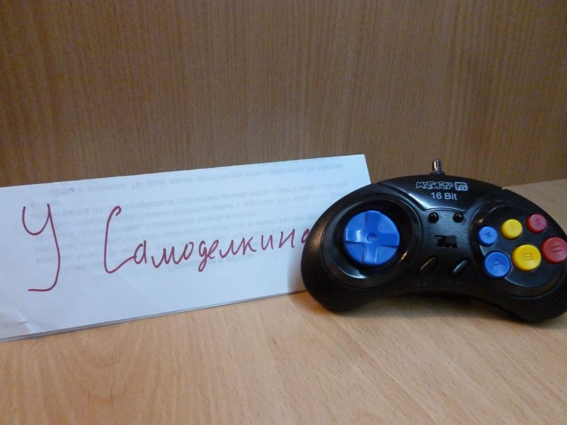
This is the second way I’ll go. For the basics, I used the old joystick from the Sega console. There is everything you need there. Four arrows (convenient for controlling cars) and 8 buttons.
So what we need:
- joystick from Sega
- Arduino Pro Mini 3.3v 8MHz
- USB-TTL
- 2 Ni-Mn batteries 1.2v 1000mA
- IR LED
- Red LED
- Blue LED
- resistor 2x75Om, 2x5Om, 1x2Om
wire
- PLSx5 connector "mother"
- hot glue
- wires
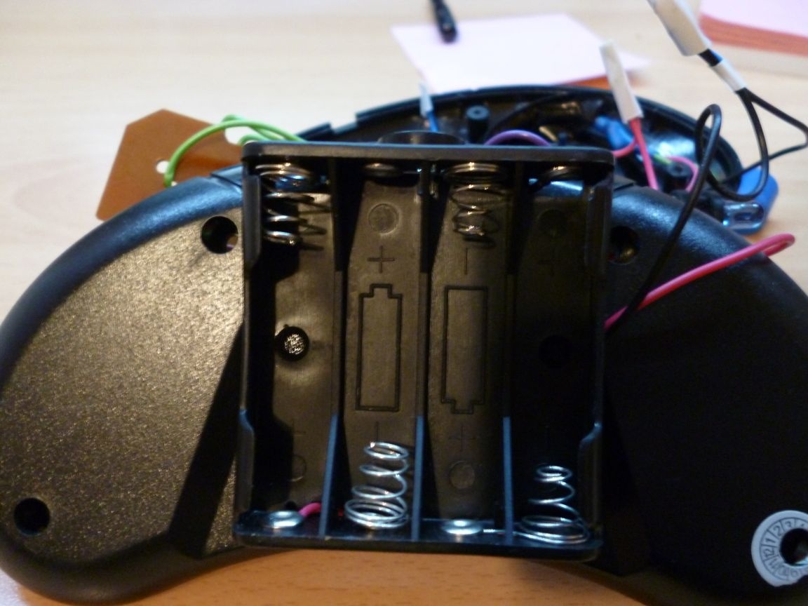
- battery compartment 4xAAA
- multi-colored wires
- soldering iron, solder, rosin
- Straight arms
Step 1 Solder
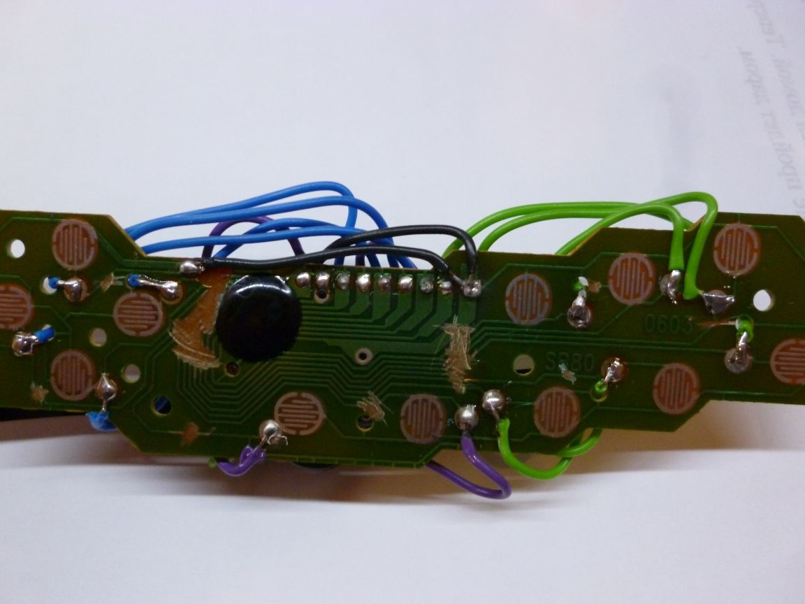
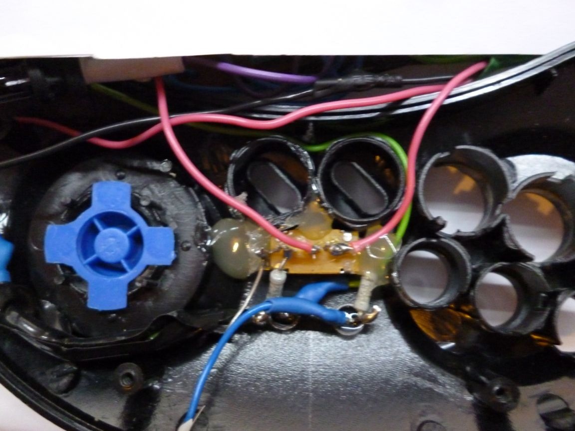
We disassemble our joystick, remove the board from it and solder all the wires from it. Next, you need to take a clerical knife or just a sharp knife and cut all the tracks from the controller on the board so that it does not interfere with us and does not conflict with Arduino. Near each button there is a small circle with a bare track. Having taken a soldering iron, it is necessary to solder to each mug along the wire, as well as finding a common wire to solder and a wire to it (common, black). Wrapping the wires back should look something like this:
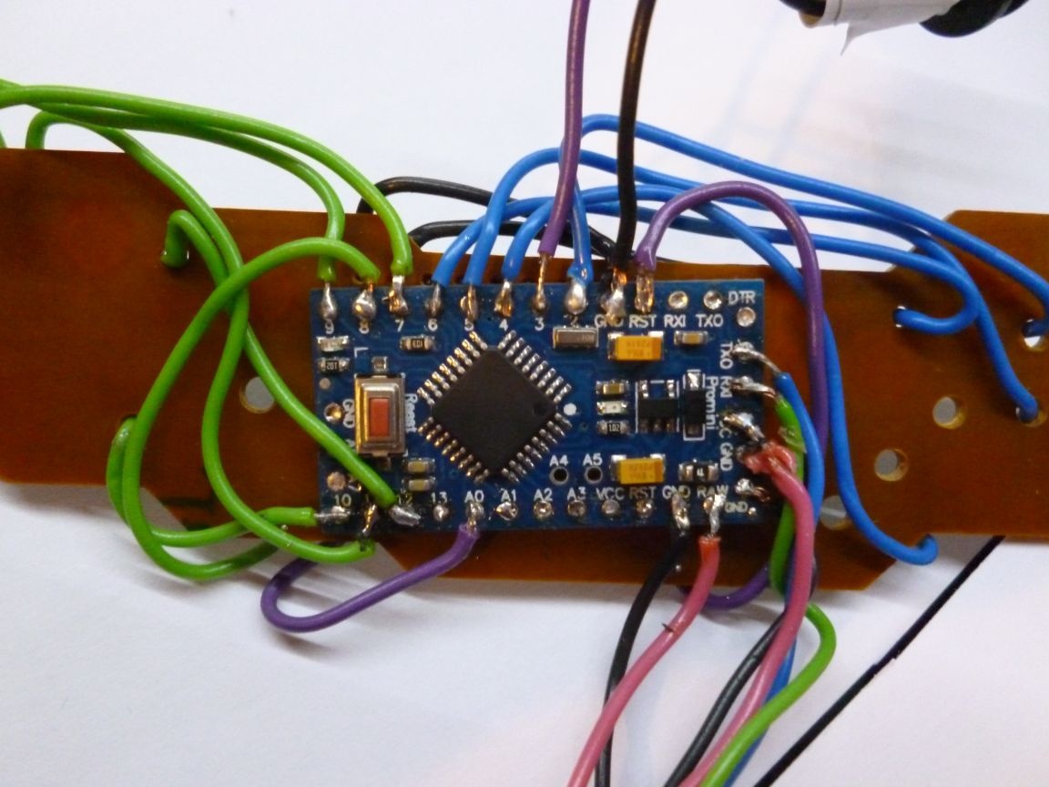
On the reverse side, on a double-sided tape we glue our Arduino. A small digression about the choice of Arduino. In principle, you can use any board, the main thing is that it fits inside the joystick.
Solder our motives according to the following scheme
Joystick Arduino
Up arrow 2
Down arrow 4
Left Arrow 5
Right arrow 6
Button A 8
B button 10
C button 7
X button 12
Y button 11
Z button 9
Start 14 button (A0)
Reset RST Button
IR LED + 3
Generic GND
Blue LED
through a 75 ohm raw resistor
Red LED
through the resistor 75 Om + 5 connectors
Let me explain: I soldered all the buttons as it was conveniently by wire, if mixed up, you just need to fix it in the sewing. The main IR positive contact must be soldered to 3! Remember to solder minus IR to GND. The Reset button is needed to restart the Arduino with firmware.
Step 2 case mode
It is necessary to think over a conclusion of wires for connection of USB-TTL. I used the connector on 5 PLS "mother". He made a suitable size slot in the right side of the joystick, inserted the connector and filled everything with hot glue. + 5v from this connector for now, just output the wire. TX to RX Arduino, RX to TX respectively. + 3.3v to 3.3 Arduino, GND to GND Arduino. He made a suitable size slot in the right side of the joystick.
To indicate the inclusion of the remote control and the battery charge, you need to drill two holes with a diameter of 5 mm in front of the joystick and insert the LEDs there. And also cut a hole for the switch.
On the inside, fill the diodes and switches with hot glue.
Step 3 nutrition
So there are two options for nutrition. I did both, but you can choose the appropriate one and use one.
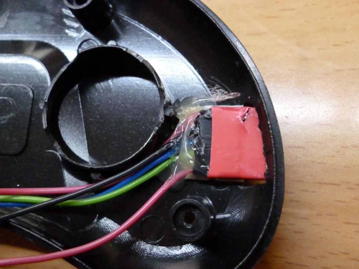
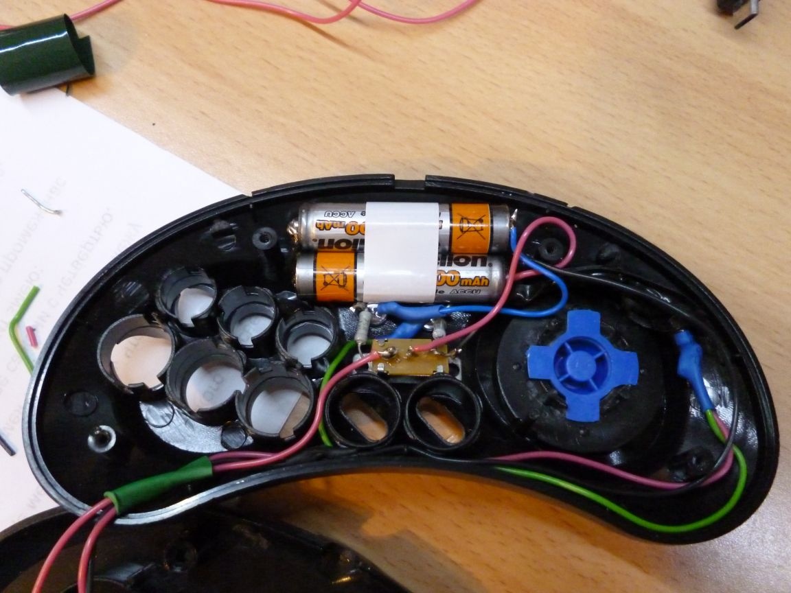
The first battery powered. To do this, solder two NI-MN batteries in series, to the pluses through the switch, solder the following 5Om + 5Om + 2Om + Diode in series and to +5 of our connector, this is for charging from USB-TTL. We wrap the resulting spike from the diode and resistors with electrical tape and lay the upper right corner. In parallel, solder our red LED through a 75 Om resistor to indicate a charge. The second position of the switch is the working wire from it goes to the RAW Arduino and again in parallel, this time a blue LED, through a 75Om resistor. Minus directly to the GND Arduino.
The batteries are located at the top of the joystick and must be glued
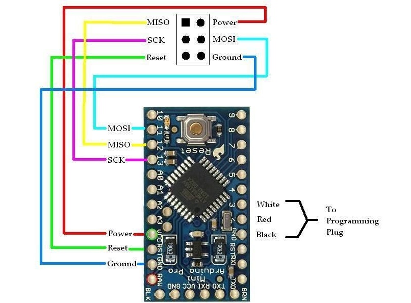
Next up are the manipulations with the Arduino. The fact is that the voltage of 2.4 volts is small, and in order to start our controller you need to change the fuse bits of the Arduino. Detailed instructions regarding the firmware of the bootloader and fuse bits are beyond the scope of this topic, and the Internet is full of schemes and options. The main result here is to disable Arduino power control. Here is the ICSP Arduino Pro Mini pinout diagram.
The second option is simpler and does not require additional manipulations with Arduino. Solder to the switch the positive wire from our battery compartment, minus to the GND Arduino. We bring the wires out by making a small cut in the case and glue the compartment to the back cover of the joystick on a double-sided tape. It gets like this:
It doesn’t look very beautiful, but it’s faster and has fewer problems.
Step 4 Assembly
So we got the following construction:
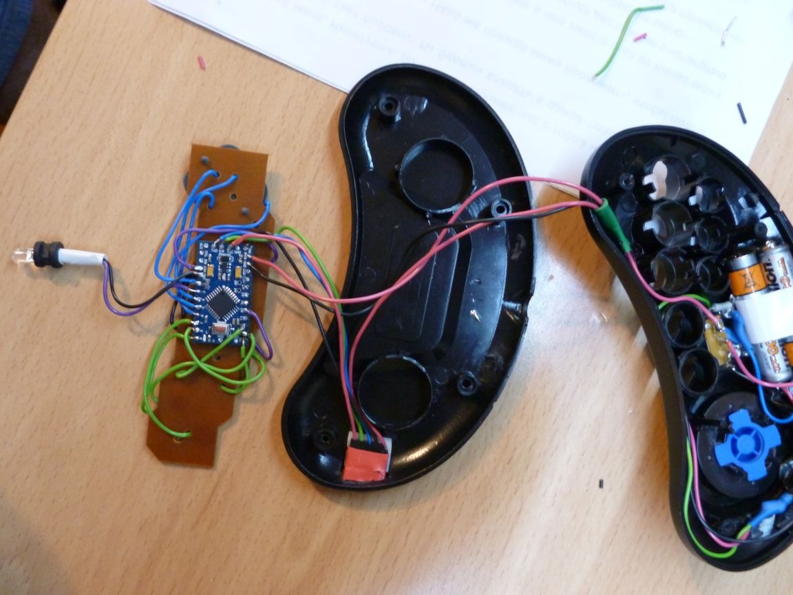
When assembling, it is necessary to lay the wires so that they are not bitten by the internal parts of the joystick. I did not succeed right away, but after five attempts everything will work out. Here is my remote control assembly.
Step 5 firmware
Our remote control is flashed through a connector connected to USB-TTL, charging is also through it. Do not forget to press Reset when pouring the scratch.
When writing the firmware, I wrote down a random set of numbers (codes) for each command (button). I use these codes when writing the firmware of a managed device. Codes are sent three times, which eliminates the possibility of skipping a command. When you release the button, a code is also sent that is used to stop the managed device.