» Electronics » Amplifiers 100 Watt Transistor Power Amplifier

100 Watt Transistor Power Amplifier


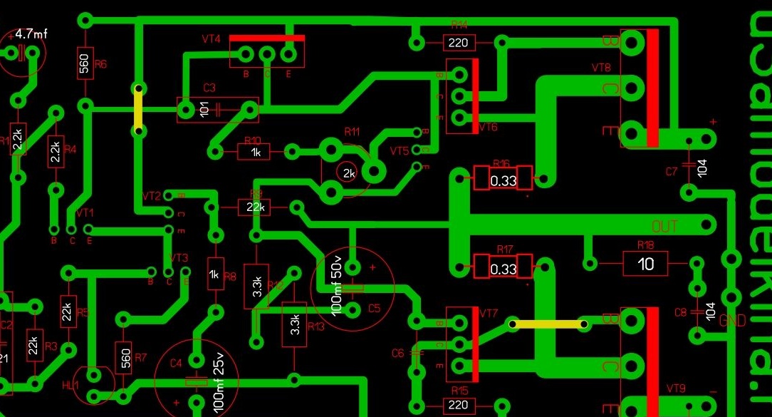
Hello! In this article I will describe in detail how to make a cool amplifier for the home or auto. The amplifier is simple to assemble and configure, and has good sound quality. Below is a schematic diagram of the amplifier itself.

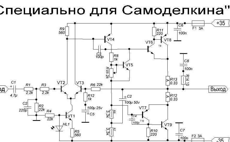
The circuit is made on transistors and does not have scarce parts. The power supply of the amplifier is bipolar +/- 35 volts, with a load resistance of 4 Ohms. When connected with 8 ohm load, the power can be increased to +/- 42 volts.

Resistors R7, R8, R10, R11, R14 - 0.5 W; R12, R13 - 5 watts; the remaining 0.25 watts.
R15 trim 2-3 kOhm.
Transistors: Vt1, Vt2, Vt3, Vt5 - 2sc945 (usually c945 is written on the body).
Vt4, Vt7 - BD140 (Vt4 can be replaced by our Kt814).
Vt6 - BD139.
Vt8 - 2SA1943.
Vt9 - 2SC5200.

ATTENTION! The c945 transistors have a different pinout: ECB and EBK. Therefore, before soldering, you need to check with a multimeter.
The LED is ordinary, green, GREEN! He is not here for beauty! And it should NOT be super-bright. Well, the rest of the details can be seen in the diagram.

And so, let's go!


To make an amplifier we need instruments:
soldering iron
-tin
- rosin (preferably liquid), but you can get by with the usual
scissors for metal
nippers
-awl
- medical syringe, any
- drill 0.8-1 mm
- drill 1.5 mm
-drill (preferably some mini drill)
-sandpaper
and multimeter.

Materials:
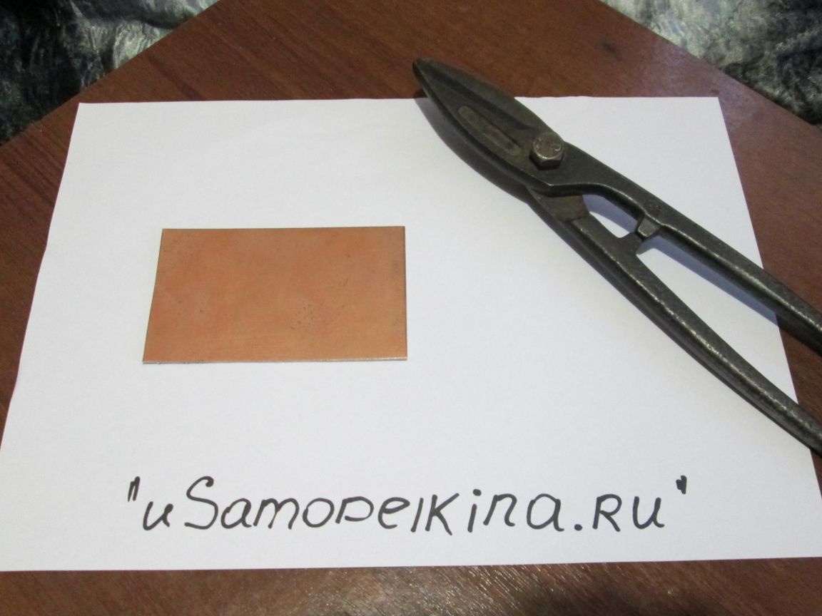
- one-sided textolite board measuring 10x6 cm
copybook sheet
-a pen
-varnish for wood (preferably dark)
- small container
-baking soda
-lemon acid
-salt.

I will not list the list of radio components, they can be seen in the diagram.
Step 1 Cooking board
And so, we need to make a board. Since I don’t have a laser printer (I don’t have anything at all), we will make the board “the old fashioned way”!
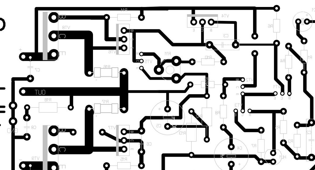
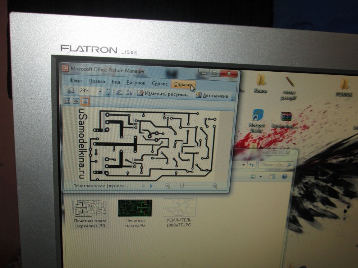
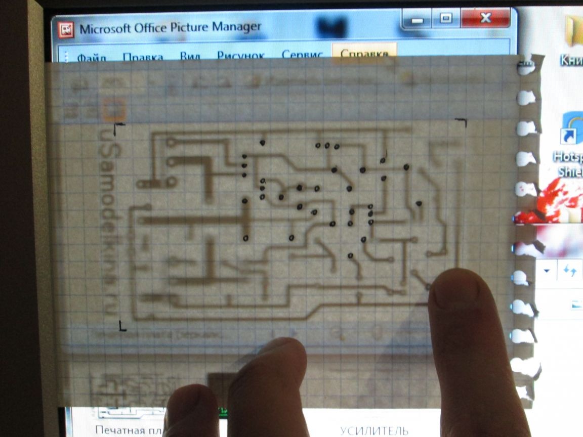
First you need to drill holes on the board for future parts. Whoever has the printer, just print this picture:

if not, then we need to transfer the marking for drilling to paper. You will understand how to do this in the photo below:

when you transfer, do not forget about the size of the board! (10 by 6 cm)


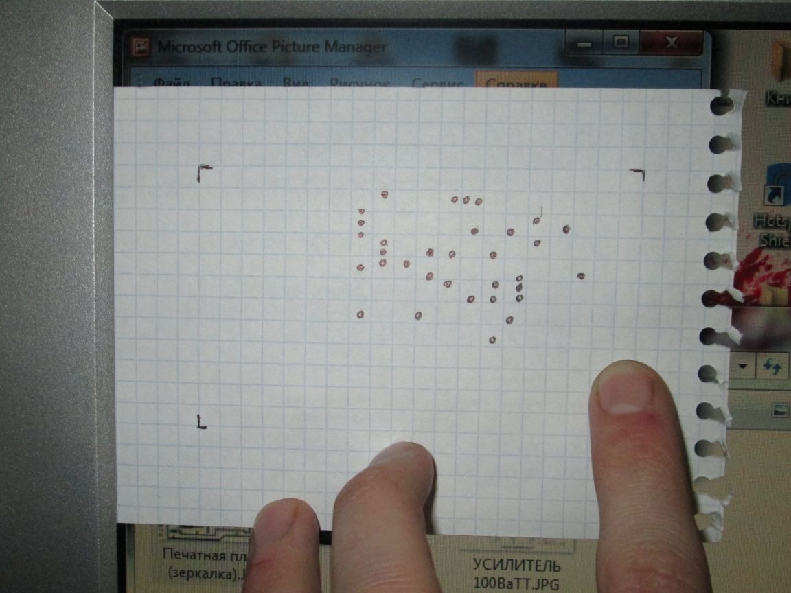
something like that!
We cut off the board size we need with scissors for metal.

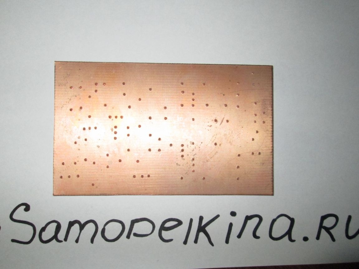
Now we attach the sheet to the cut out board and fix it with tape so that it does not move out. Next, we take an awl and outline (by points) where we will drill.

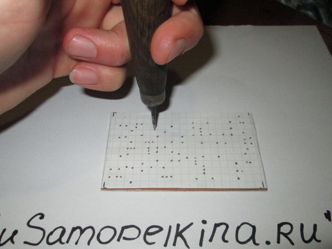
You can certainly do without an awl and drill right away, but the drill can move out!

Then it should turn out like this:

Now you can start drilling. We drill holes 0.8 - 1 mm. As I said above: it is better to use a mini drill, since the drill is very thin and breaks easily. For example, I use a motor from a screwdriver.


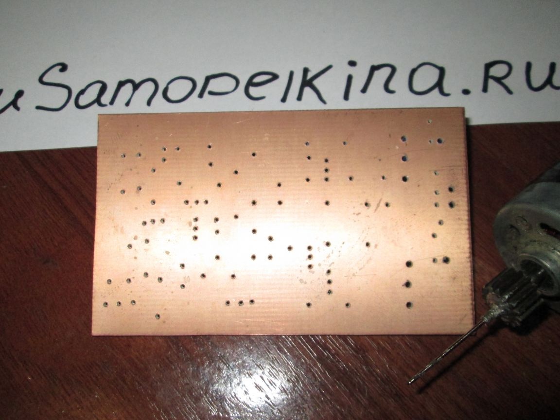
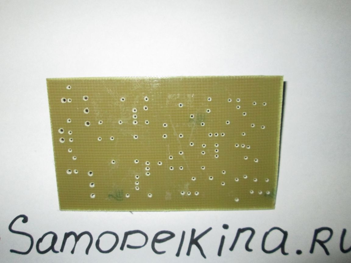
We drill holes for transistors Vt8, Vt9 and for wires with a drill of 1.5 mm. Now we need to sandpaper our board.

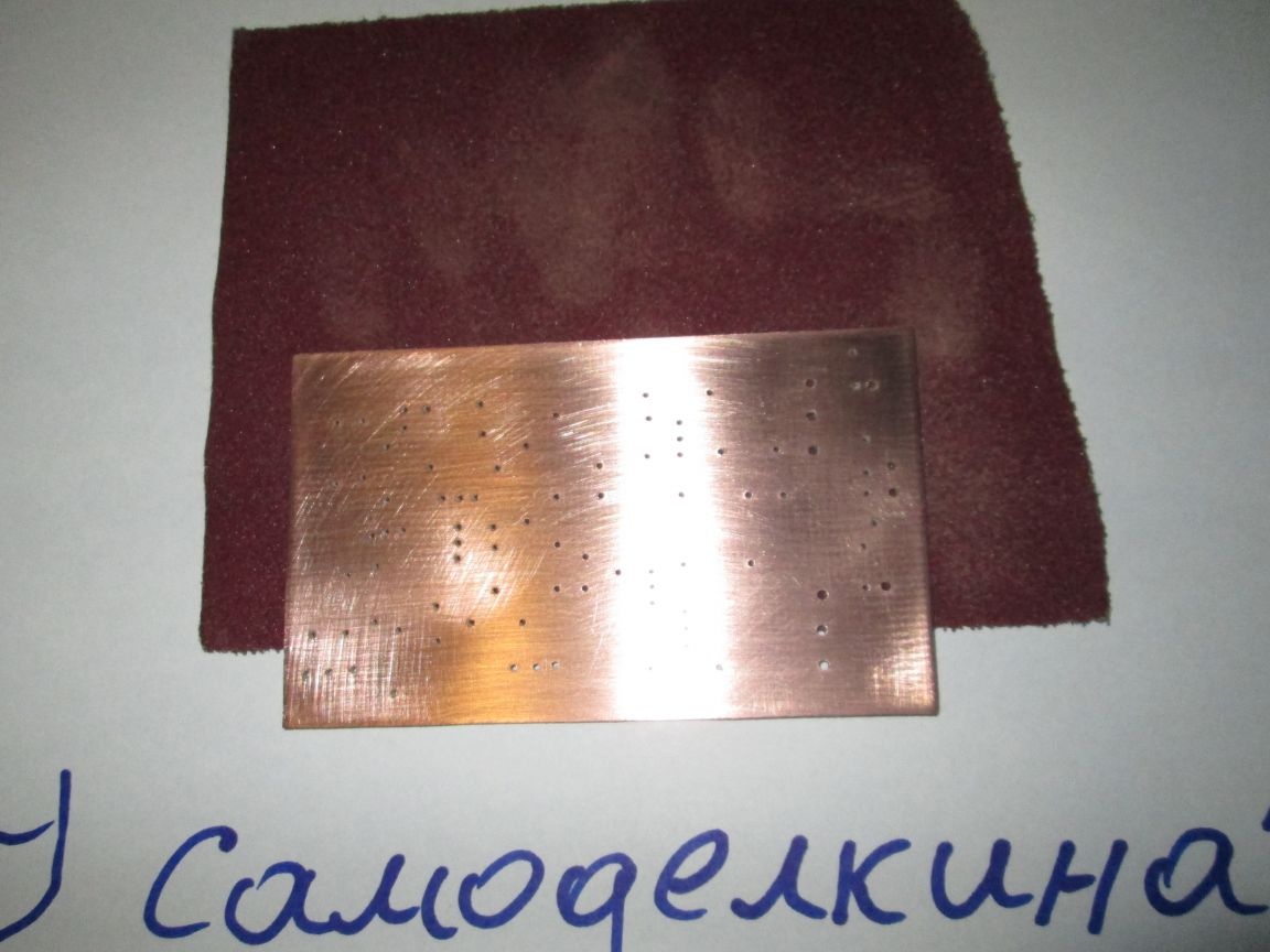
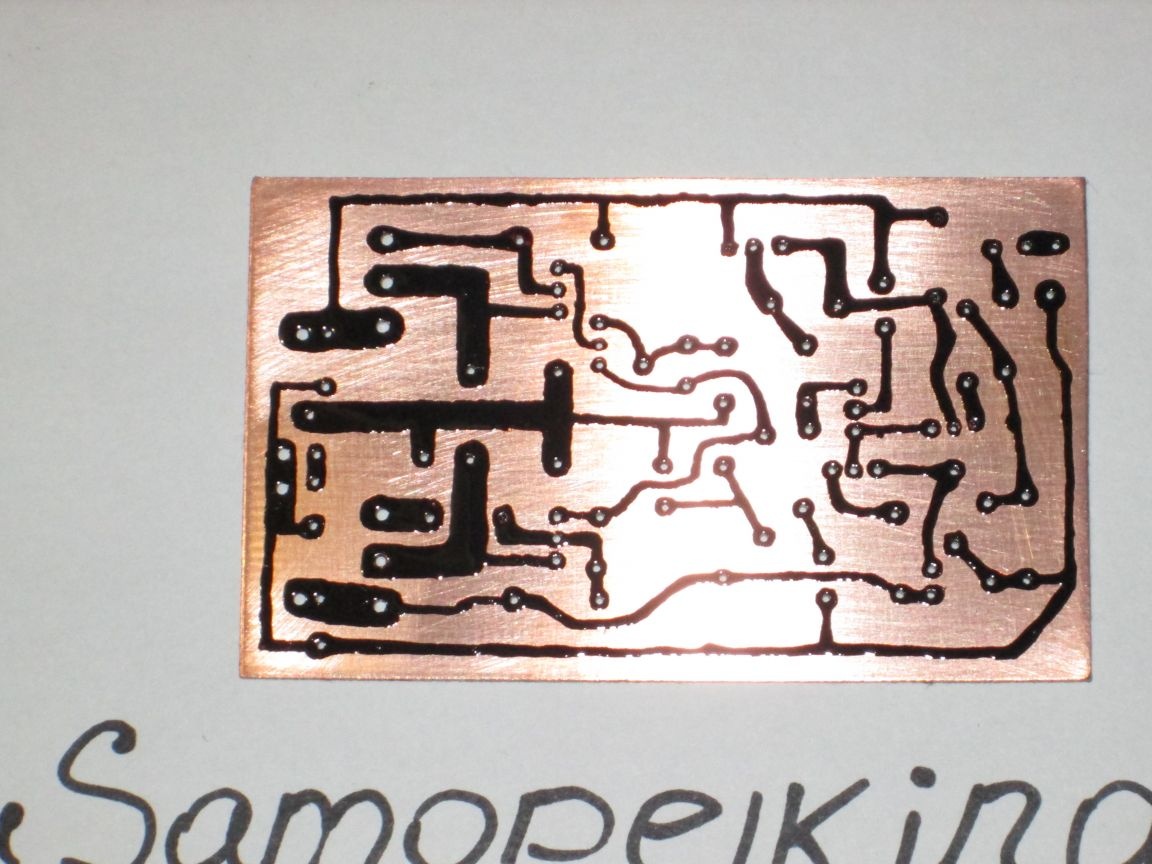
Now you can start drawing our tracks. We take a syringe, grind the needle so that it is not sharp, we collect varnish and go!

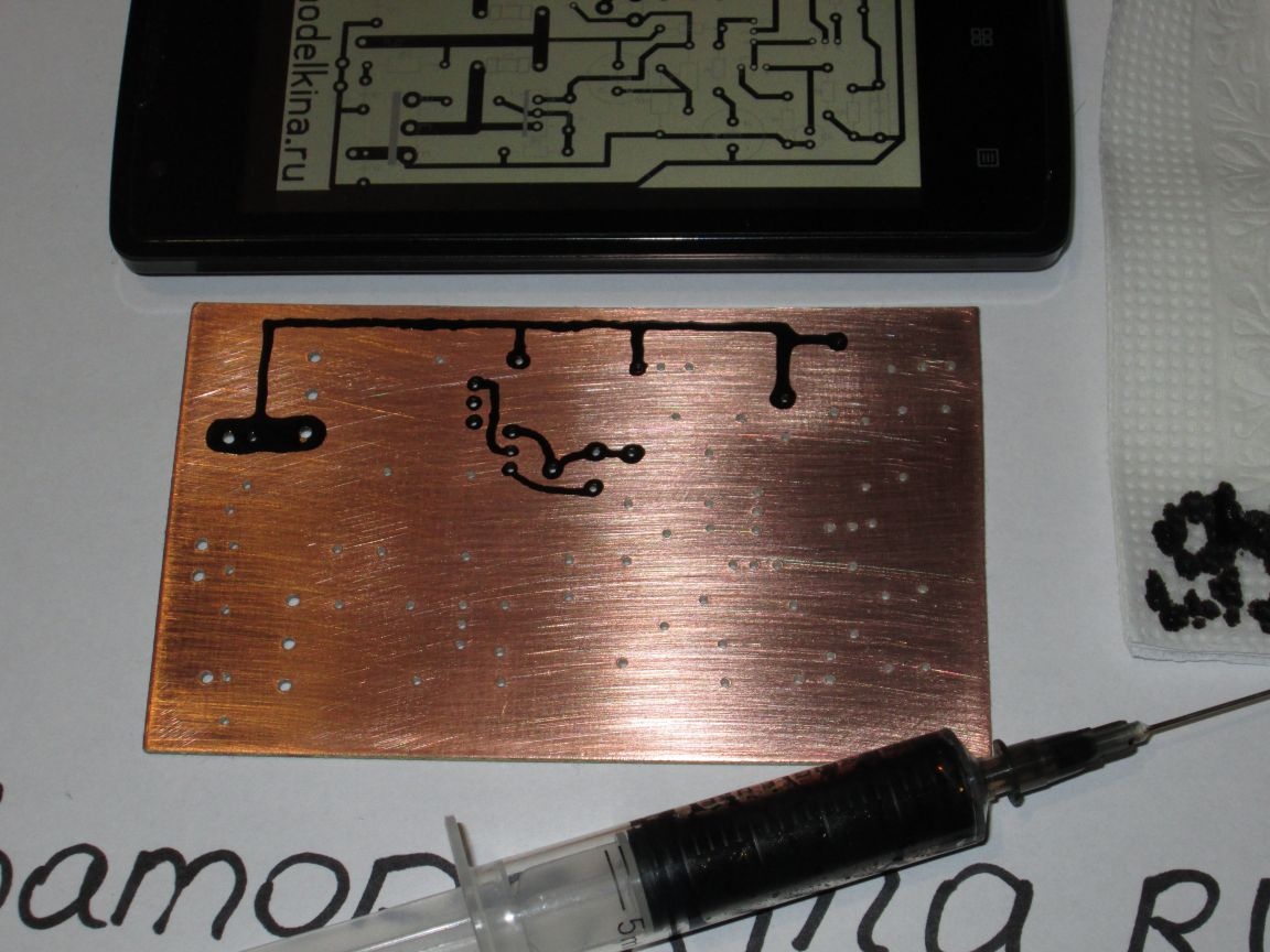
It is better to trim the jambs when the varnish has already hardened.

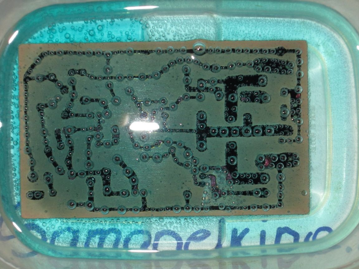
Step 2 Poison the board
To etch boards, I use the simplest and cheapest method:
100 ml of peroxide, 4 teaspoons of citric acid and 2 teaspoons of salt.

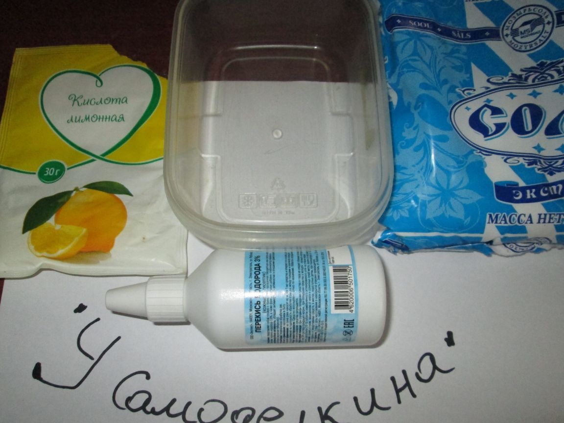
Stir and immerse our board.


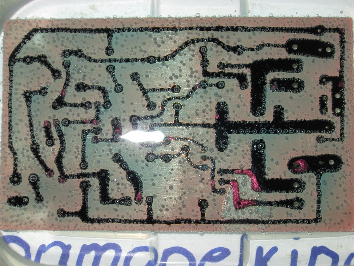
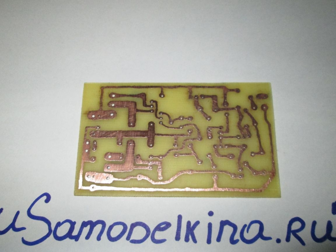
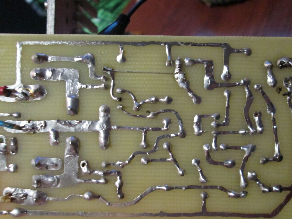
Next, we clean off the varnish and it turns out like this!

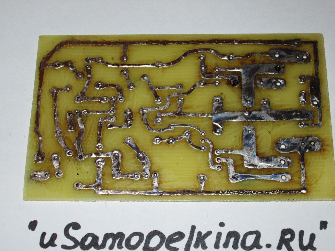
It is advisable to immediately cover all the tracks with tin for the convenience of soldering parts.

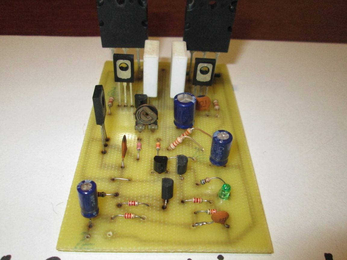
Step 3 Soldering and tuning
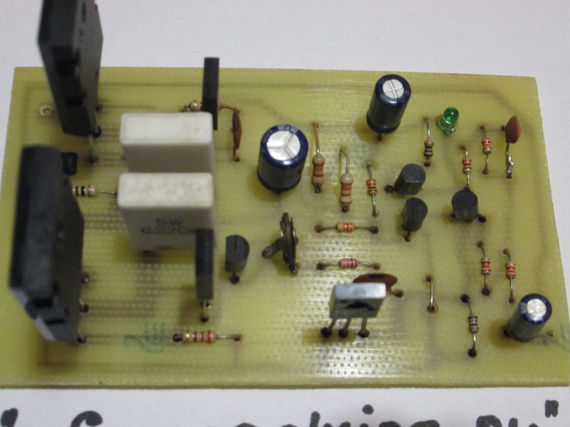
It will be convenient to solder in this picture (view from the side of the parts)

For convenience, from the beginning we solder all small parts, resistors, etc.

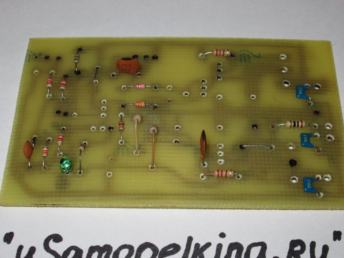
And then everything else.

After soldering, the board must be washed from rosin. You can wash it with alcohol or acetone. You can even use gasoline to the extreme.

Now you can try to turn it on! With proper assembly, the amplifier works immediately. The first time you turn on the resistor R15, turn it towards the maximum resistance (measure with the device). Do not connect the column! Output transistors are MANDATORY to the radiator, through insulating gaskets.

And so: they turned on the amplifier, the LED should be on, we measure the output voltage with a multimeter. There is no constant, then everything is fine.
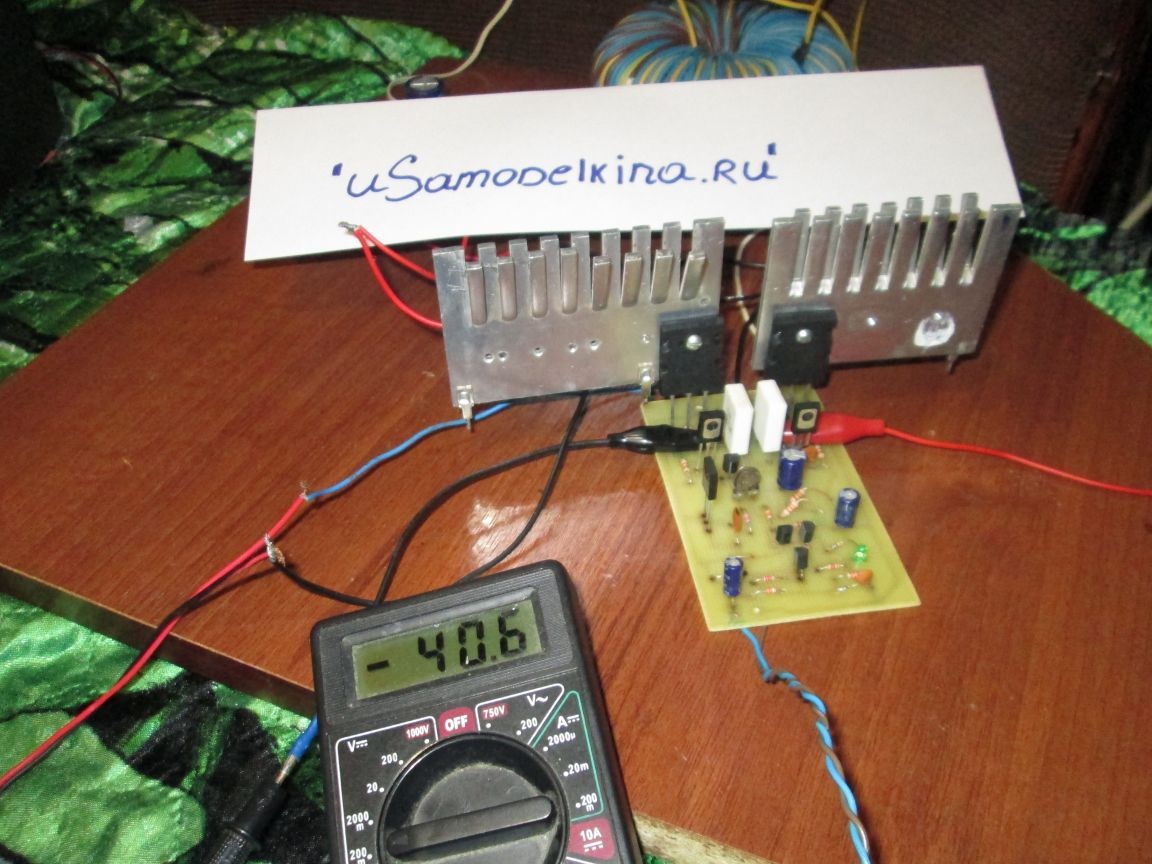
Next, you need to set the quiescent current (75-90mA): for this, close the input to ground, do not connect the load! Set the mode to 200mV on the multimeter and connect the probes to the collectors of the output transistors. (marked with red dots in the photo)

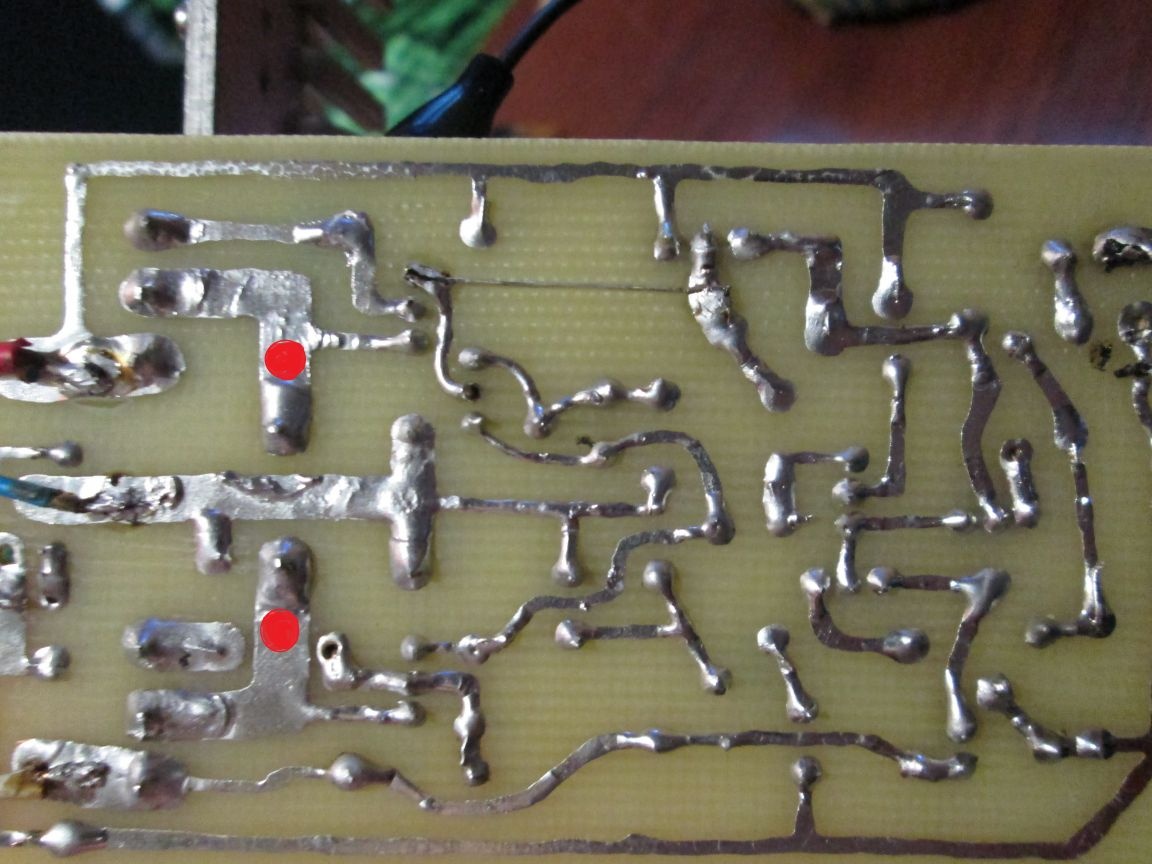
Next, by slowly rotating the resistor R15, you need to set 40-45 mV.

Exposed, now you can connect a speaker and drive the amplifier at low volume for 10-15 minutes. Then again it will be necessary to correct the quiescent current.
Well, that’s it, you can enjoy it!

Here is the video of the amplifier:
8.2
7.9
7.3

Add a comment

    • smilesmilesxaxaokdontknowyahoonea
      bossscratchfoolyesyes-yesaggressivesecret
      sorrydancedance2dance3pardonhelpdrinks
      stopfriendsgoodgoodgoodwhistleswoontongue
      smokeclappingcraydeclarederisivedon-t_mentiondownload
      heatirefullaugh1mdameetingmoskingnegative
      not_ipopcornpunishreadscarescaressearch
      tauntthank_youthisto_clueumnikacuteagree
      badbeeeblack_eyeblum3blushboastboredom
      censoredpleasantrysecret2threatenvictoryyusun_bespectacled
      shokrespektlolprevedwelcomekrutoyya_za
      ya_dobryihelperne_huliganne_othodifludbanclose
74 commentary
Guest Roman
It would not hurt the view of the arrangement of components on the board without tracks
Guest Roman
It would be nice if the layout of the elements on the board
Guest Michael
This seems to be Rod Elliott ULF 50-100W Power supply from ± 20 V to ± 40 V, respectively. For use in 4 ohms (including a bridge load of 8 ohms), do not exceed ± 25 V and do not exceed a quiescent current of 1.5 A. The amplifier will operate as a Class-A up to about 9 W at 4 Ohms, and then switch to Class mode -AB. http://sound-au.com/project3b.htm
Guest Alexander
Hello! Tell me where did you get these transistors, and are they original?
Vt8 - 2SA1943.
Vt9 - 2SC5200.
Guest Victor
Hello, the output is a constant of 1.5 volts, what should I do?
Is your food symmetrical?
Did you make or reproduce a signet according to the scheme?
If you reproduced printing, then check the installation, the transistor modes.
If it does not help, then describe the situation.
Guest Victor
Hello, the output is a constant of 1.5 volts, what should I do?
Quote: Guest Victor
what is wrong with VT4? I don’t see anything suspicious yet.
How will the signal get to the VT6 base?
Quote: Guest Victor
How to make what would earn that?
Already two times I answered you what needs to be done first. ((
Guest Victor
Sorry, I'm new to what's wrong with VT4? I don’t see anything suspicious yet. How to make what would earn that?
Quote: Guest Victor
How to check transistor modes?
Measure the voltage at the terminals of the transistors and the quiescent current of the output transistors.
Quote: Guest Victor
I did not see a circuit error.
Pay attention to the collector VT4.
Quote: Guest Victor
Yes, I gathered without understanding it.
What's the point?
Quote: Guest Victor
I'm a beginner so far ... much remains to be learned
Then in vain began with such a project. It was necessary to start with something simpler, so as not to discourage.
Guest Victor
How to check transistor modes?
I did not see a circuit error.
Yes, I gathered without understanding it. I'm a beginner so far ... much remains to be learned
To start, describe it. And answer the questions that I asked you.
Guest Victor
So how to solve the problem?
Quote: Guest Victor
. The diode does not light up.
It should glow slightly, not brightly.
Quote: Guest Victor
Transistors are normal, checked more than once.
I didn’t ask that.
Quote: Guest Victor
What mistake?
Do not see the error in the diagram? You probably just reproduced the signet without understanding how the circuit works?
Guest Victor
Transistors are normal, checked more than once. What mistake?
Guest Sergey
Sorry, but what mistake is that?
Did you fix the error on the diagram? If corrected, then check the transistor modes.
Guest Victor
Assembled this amplifier. I can’t understand anything ... the diode does not light up. When connected, the speaker buzzes hard and as if absorbed into itself. If you change the polarity, on the contrary, is inflated. For sec 5 you turn on 2sa1943 ... because I have two pairs, I changed them, there is no sense. I checked for a breakdown ... all two pairs are whole. Please help me decide.
Instead, you can put three series-connected transitions BE of low-power silicon transistors, preferably the same type as VT1. You can KS119 stabilistor, at worst - with silicon low-power diode.
Its role is stabilization and thermal compensation of the voltage at the input of the current generator.
What diode to replace the LED?
Guest Vyacheslav
What to put instead of the LED and what is its role
Help, I got a mirror board. How now, to install parts on the solder side, or turn transistors over?
Bender, don’t insert third-party program files here - it’s not known how the engine of this site makes friends with him. Put the lay.-file on an external secure resource-carrier / repository of FAQs, for example, on the Yandex disk, and here give a link to it - who needs to pick-up from there.
In fact, with the voltage indicated on the diagram, the amplifier can produce 100 watts. If it is assumed that the output stage should work in the B-class, then radiators 200-300 square meters. see maybe it will be enough. But the circuit contains a thermal compensation unit, and the list of used p / components shows a pair for the 2SA1943 / 2SC5200 "exhaust", which implies the operation mode of the output stage in the AV class at a quiescent current of 100-120 mA. Based on this, the area of ​​the radiator with passive cooling for each transistor should be at least three times greater than that specified by you. Otherwise, instead of an amplifier, you get a room air heater; and if the device is for use in a typewriter, then in winter it will be possible to ride without a stove. ;)
Author
Yes, but how to insert it here ?! scratch
Does anyone have a signet in SL?
Good afternoon. Have you performed experiments on adjusting the volume level on this amplifier?
If your output transistors are warming, then it means they are finished. It is necessary to solder all the transistors in turn for dialing. There’s nothing special to break here! Details minimum. I collected this amplifier and there were no problems.
How do you understand 31 volts of bipolar? If not the same as in the picture, then this is not bipolar.
Once again, I will advise you to read in a physics textbook about how the current differs from voltage.
And in your case, presumably, an open in the circuit between VT4 and VT7 base. Measure the voltage between output and zero.
Meryl, as shown by the author, has a quiescent current. At first I turned on 200m but the device went off scale. Then he switched to 20v, showed 4 volts where you need to measure the quiescent current. If I measure volts or milliamps, then how many volts should be where the quiescent current is measured. It turns out there should not be stress at all. Because the current is measured at break. Right or wrong.
Quote: leprex
4 volts is a type of quiescent current. Why I wrote between the bases (I made a mistake), I can’t understand why the milliampere when the multimeter is dividing 200m in the constant voltage range (200m, 2000m, 20,200,1000); Is it not volts ???
Again - porridge from words. Where did you turn on the device? In what mode? At what limit? What did you get?
Quote: leprex
I can’t explain. I used amperes, but I don’t understand how milliamperes. If not difficult to explain.
Read in the physics textbook for grade 8. Or where does the electricity start now?
I can’t explain. Details that did not inspire confidence changed. 4 volts is a type of quiescent current. Why I wrote between the bases (I made a mistake), I can’t understand why the milliampere when the multimeter is dividing 200m in the constant voltage range (200m, 2000m, 20,200,1000); Is it not volts ??? Sorry about this topic not so long ago. I collected current tda7294 there were no problems. I used amperes, but I don’t understand how milliamperes. If not difficult to explain.
Quote: leprex
In general, I got to the point that the quiescent current of 4 volts, the output keys are very hot.
It is difficult to understand you: then you have a 0.5 mA rest current, but the output transistors heat up, which, in principle, cannot be with such a current; then you have 4 V - quiescent current)), then 4 V - voltage between the bases.
the quiescent current was 0.5m; I don’t know how correctly a milliamp or millivolt.

In general, it is difficult to help a person who does not distinguish current from voltage.
F2 is not worth it.
Very bad.
F2 is not worth it. I sin that before that the output keys were burned. The quiescent current was 0.5m I do not know how the milliamp or millivolt is correct. Right now, between the 4 volt key bases. The keys are very hot.
In general, I got to the point that the quiescent current of 4 volts, the output keys are very hot.
Quote: leprex
The rest current is always 0.5 millivolts.

Milliampere, probably? )) Is F2 intact?
Presumably, the lower output arm is closed due to a malfunction of the differential stage, since the current with a healthy dip should be about 2 mA even if the VT4, VT5 circuit breaks.
I feed 31 volts of bipolar to the amplifier at the output of 31 volts of constant current. The column did not include. Entrance closed to a common. The quiescent current is always 0.5 millivolts. Punched c945 replaced with c1815 did not help. It does not heat up
Specify what you had in mind. There should be the same constant voltage at the input and output, equal to zero. If this is not the case, write specifically what is really there.
Hello. My monster was gathering dust. And so I decided to start it again, but it wasn’t here that the output constant was the same as the input, what could be the matter?
In cars, amplifiers are made according to the bridge circuit of power addition. And this one is for the home.
Also for your information: there is an error in the diagram - there should be a connection of the VT4 and VT5 collectors. And VT6 burned out because its base current was unlimited due to the breakdown of VT4.
Thanks a lot. The reason was in vt4. Put kt814b turned on and everything is ok. No smoke or clicks
Checked vt4 squeaks all. Between e and k. And between k and b. Is it a marriage or should it be? Right now I will put as the author wrote
Assembled a similar scheme in 19xx some shaggy year. The possibilities of choice in detail (transistors, etc.)
then there was none. There were no complementary (pairs) vehicles ...
For this amplifier, the shoulders should be identical.
Instead of BD139, you can put KT815G. And then VT7 needs KT814G. These are couples.
Trimmer resistor (R15) I had 500 ohm with an additional constant (750 ohm)
And if you want to get 100 watts, then you need to make WIDE tracks on the circuit board (and the wires are also thick). Tk currents under 5 Amps
Instead of the LED, it is better to put the KC119 stabilizer. Or 2 consecutive diodes ...
The C2 + R7 chain is unsuccessful here.
Nutrition is how it is made from trance (?) With a midpoint? Are electrolytes the same?
+ 0- I meant bipolar nutrition.
Quote: Ivan_Pokhmelev
Can I put kt815b or kt817g instead of bd139 ??

See datasheets on them.
Quote: leprex
From bd139 he clicked.

Check VT4 and the lack of snot on the board between its K and E.
Once again I ask: what is "+ 0-"?
From bd139 he clicked. Kayuk him. R15 2.2k measured by the device the maximum resistance was. Can I put kt815b or kt817g instead of bd139 ?? At hand they are current.

We advise you to read:

Hand it for the smartphone ...