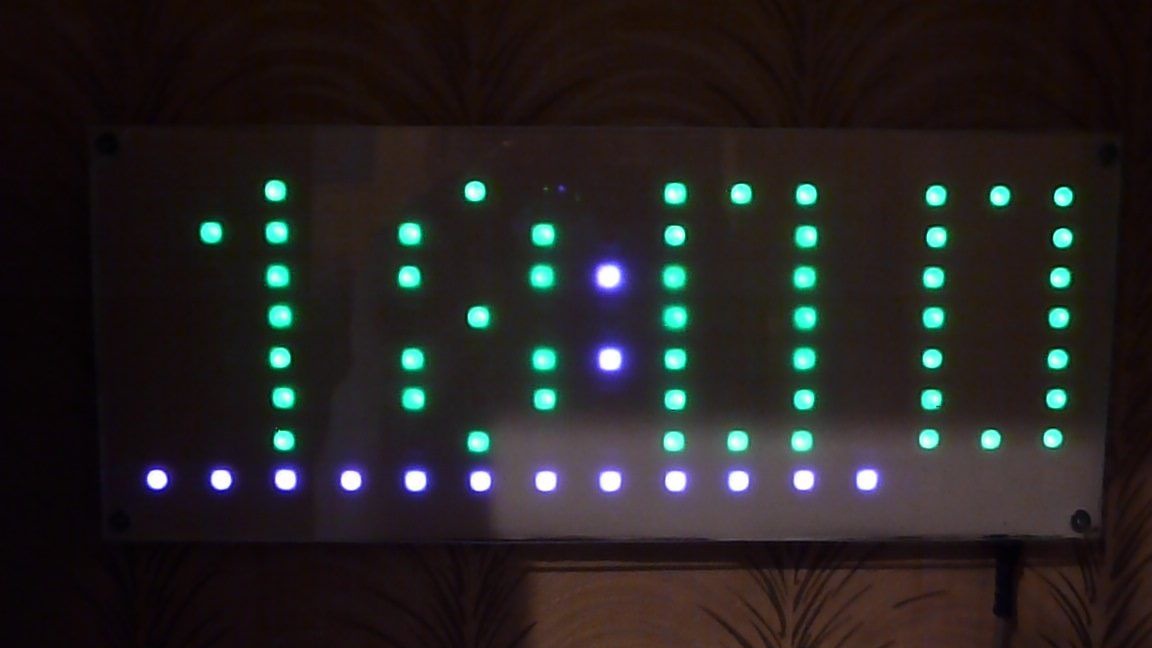
I stared at the WS2812 LEDs for a long time and finally decided to order them. I didn’t have a concrete idea, but when they came to me, I decided to make a small LED matrix. The matrix size turned out to be 15 x 8. And as an application, I made a clock from the matrix. Controller I chose ESP 8266 - 12E. My choice is not casual, ESP is needed to connect to a Wi-Fi router and synchronize time via the Internet.
So, let's start, we need:
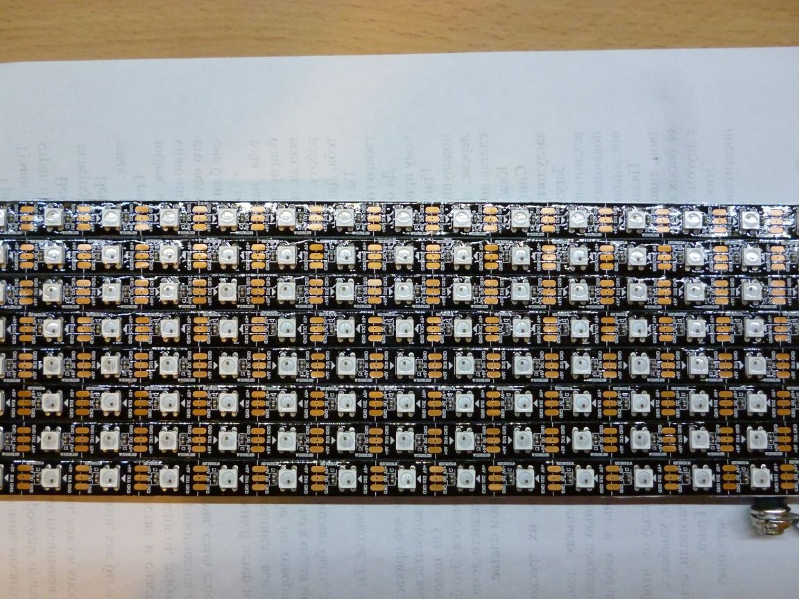
- WS2812 tape with 120 LEDs, 60 pieces per meter ()
- ESP 8266 - 12E ()
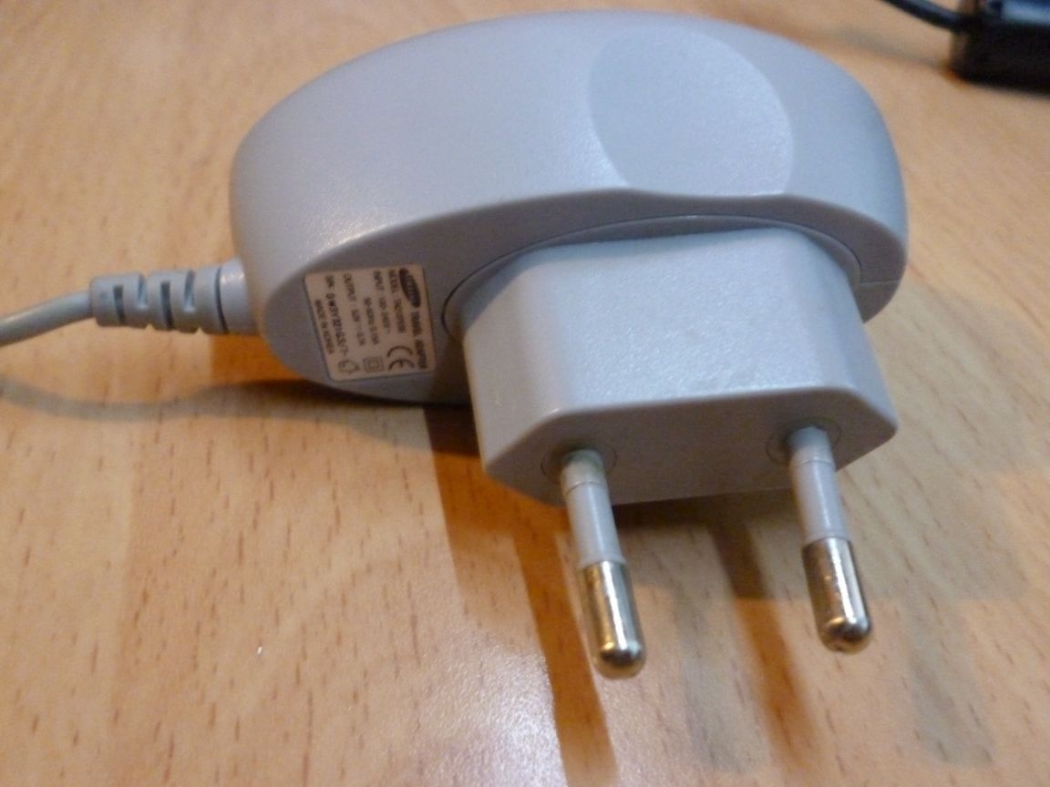
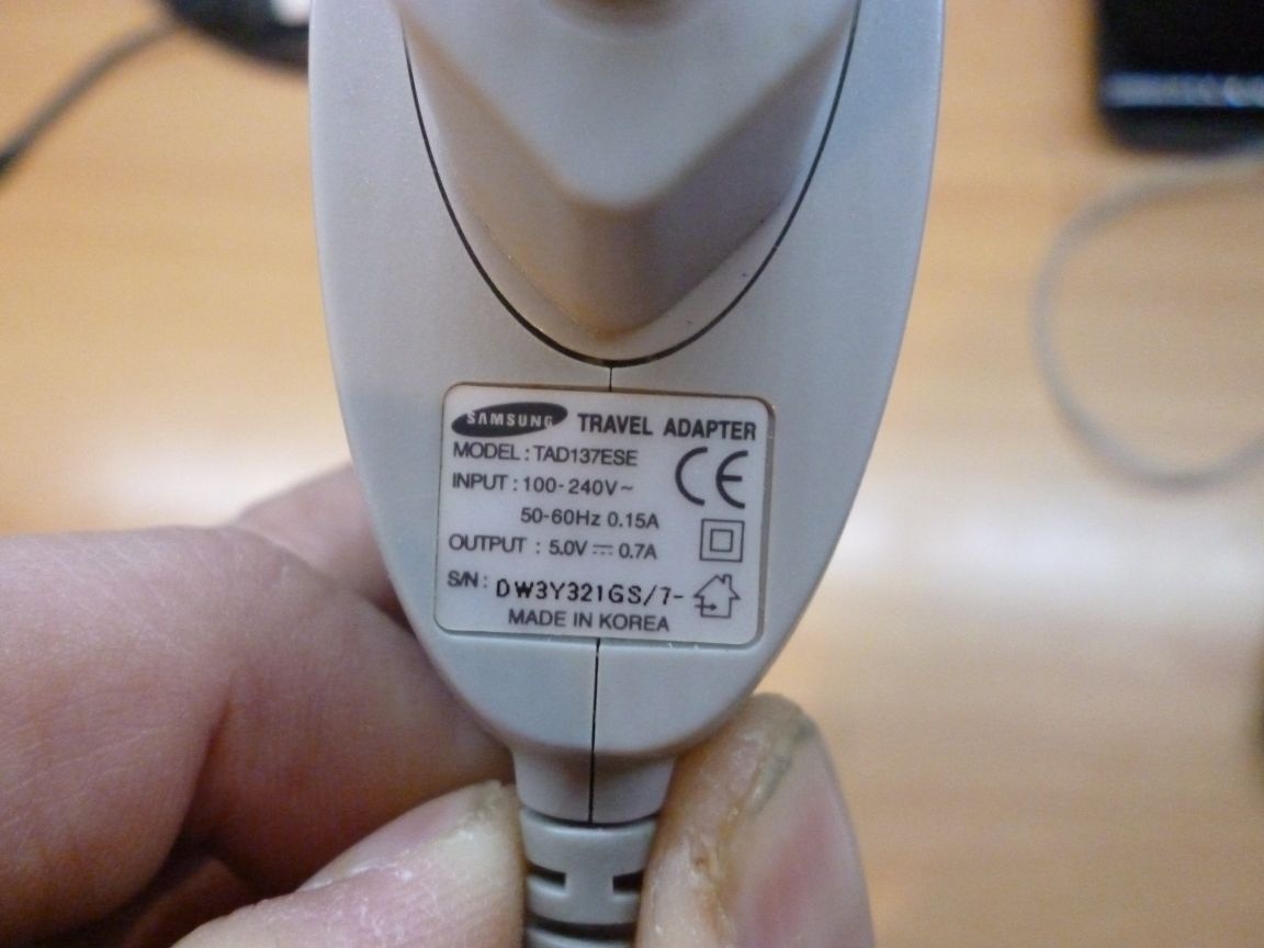
- unnecessary, but working charge from the phone, or a 5 volt power supply
- voltage regulator 3.3v
- resistors 10 kOm 0.25 W 5pcs.
- switch
- button
- wires
- PLS connector
- USB-TTL
- transparent plastic 2 mm
- light filter
- 3x20 bolts
- nuts and washers 3mm
- drill 3.2
- drill or screwdriver
Step 1 cutting plastic
To protect the matrix, we need to cut a rectangle out of a transparent (preferably matte or milk plastic, then you do not have to use a light filter) plastic with a size of 260x105 mm. And also drill 4 holes with a diameter of 3.2 mm for fastening. Drill in the corners, indented 5 mm from each side. Do this very carefully and lay the plastic on a wooden base. During my work, one corner broke away, but I stuck it and almost imperceptibly.
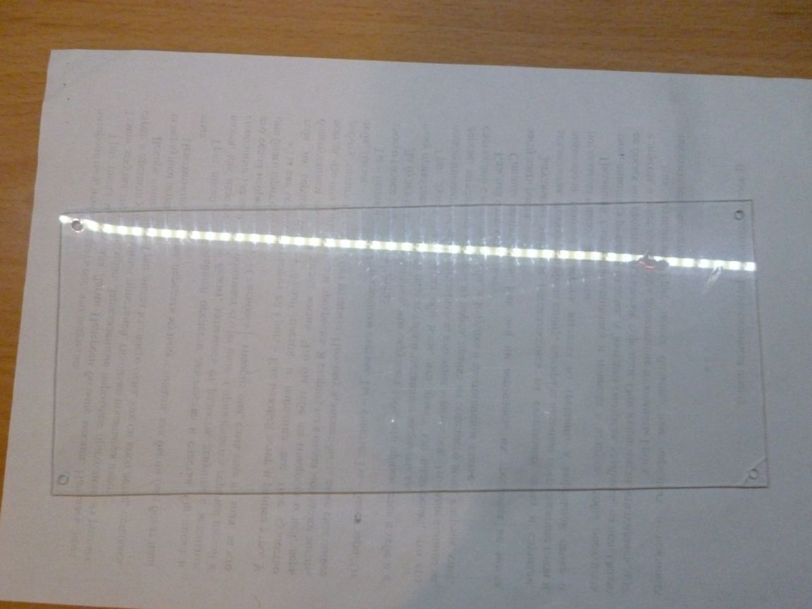
As the basis for the matrix, I used the same plastic. Cut a rectangle of 252x85 mm. You can use any other plastic or take, for example, thin plywood, the main thing is to get a fairly strong base. We will stick our LED strip to it. We cut the tape into strips of 15 diodes. This must be done carefully and strictly along the cut lines. We glue our strips horizontally on the base, starting from the top. Please note that the input signal must be supplied in the correct direction, for this purpose the arrow is shown on the tape direction. Therefore, we glue the first strip from left to right. IN (input) on the tape should be on the left, and OUT (on the right). Glue the next strip on the contrary, from the right - to the left. The third again from left to right. Etc. If you follow the signal path, it should turn out in a zigzag fashion, starting from the upper left corner. The main thing is not to get confused and not to confuse. Next, solder our stripes with short wires. + 5 from the first cavity to +5 the second. GND to GND. From the OUT of the first strip to IN of the second strip, from the OUT of the second strip to IN of the third, and so on. We solder the wire to the IN of the first strip, which we then solder to the ESP. K +5 of the first strip is red, K GND is black. It turns out the following.
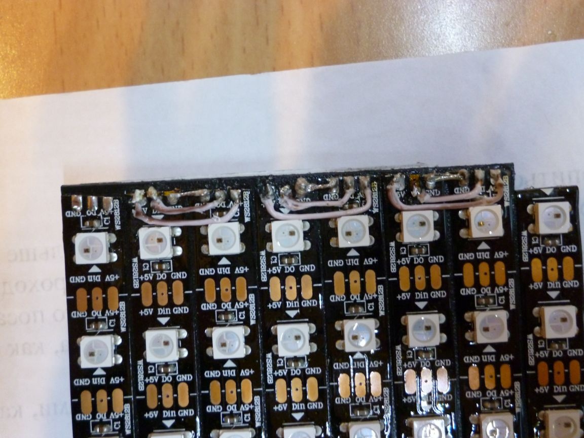
ESP will be located on the back side of the base, so the first strip, in the place of soldering, is bent to the back side.
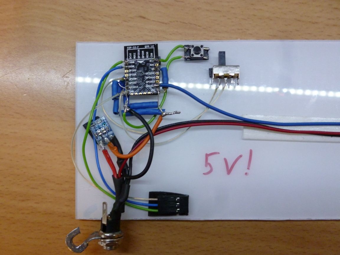
Step 2 solder
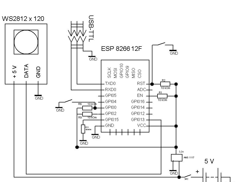
So, to run and flash the ESP-8266, you need to do a minimum binding. Only the VCC pin is connected directly to the power supply, the remaining pins: CH_PD, RESET, GPIO0, GPIO2, must be pulled to the power supply (VCC) via a resistor. 10kOm resistors can be replaced with others, from 4.7kOm to 50kOm, except for GPIO15 - its value must be up to 10k. Directly, to the minus (GND) of the power supply, we connect only GND, and we also pull GPIO0 through the resistor to 10kOm, to put the module into firmware download mode, to GND. We connect our matrix to GPIO13. The wire must be soldered to the IN of the first strip. Here is a diagram.
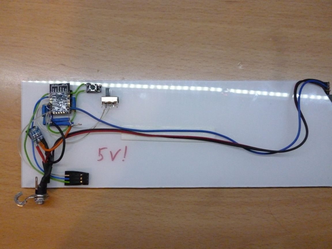
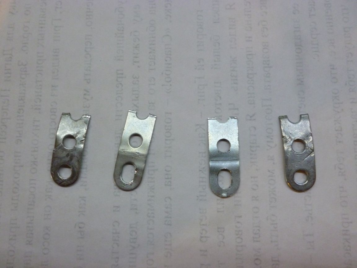
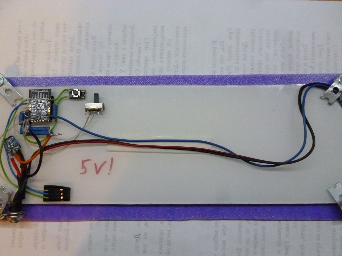
We glue all the details on a double-sided tape on the back of our base. To make it convenient to connect and disconnect the power supply, the power connector is fastened with a bracket from a metal designer. You can use any other material, the main thing is that the connector holds firmly and does not fall off when connected - turning off the power. For the firmware, a three-wire PLS connector is output. We get the following construction.
Step 3 assembly
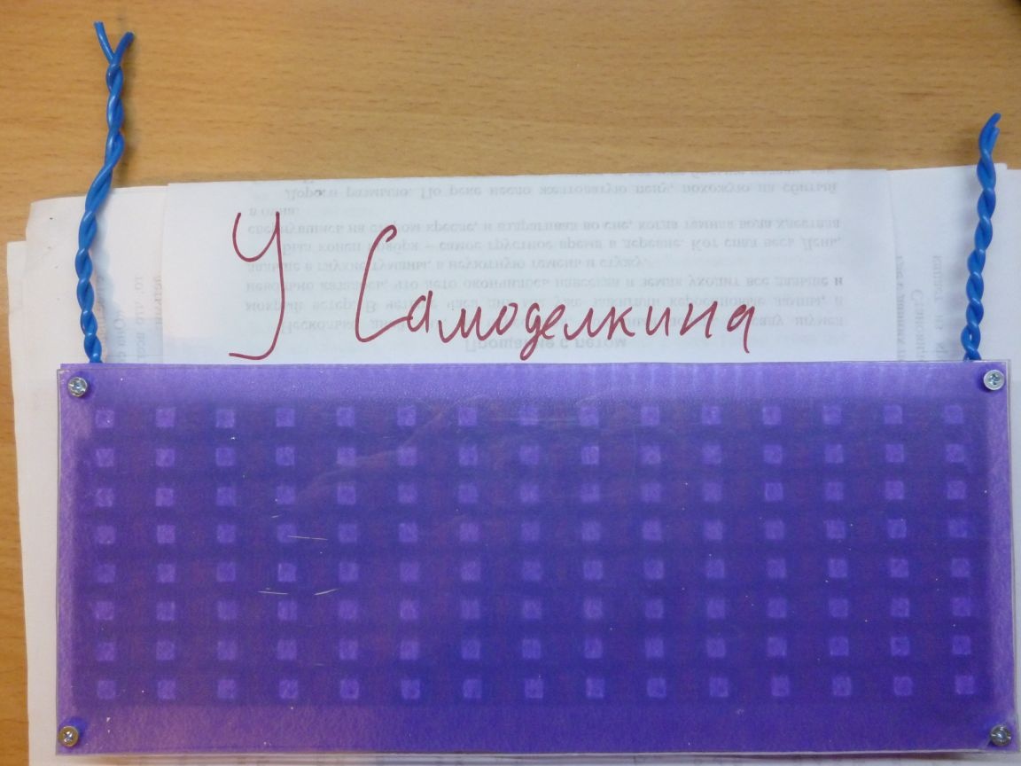
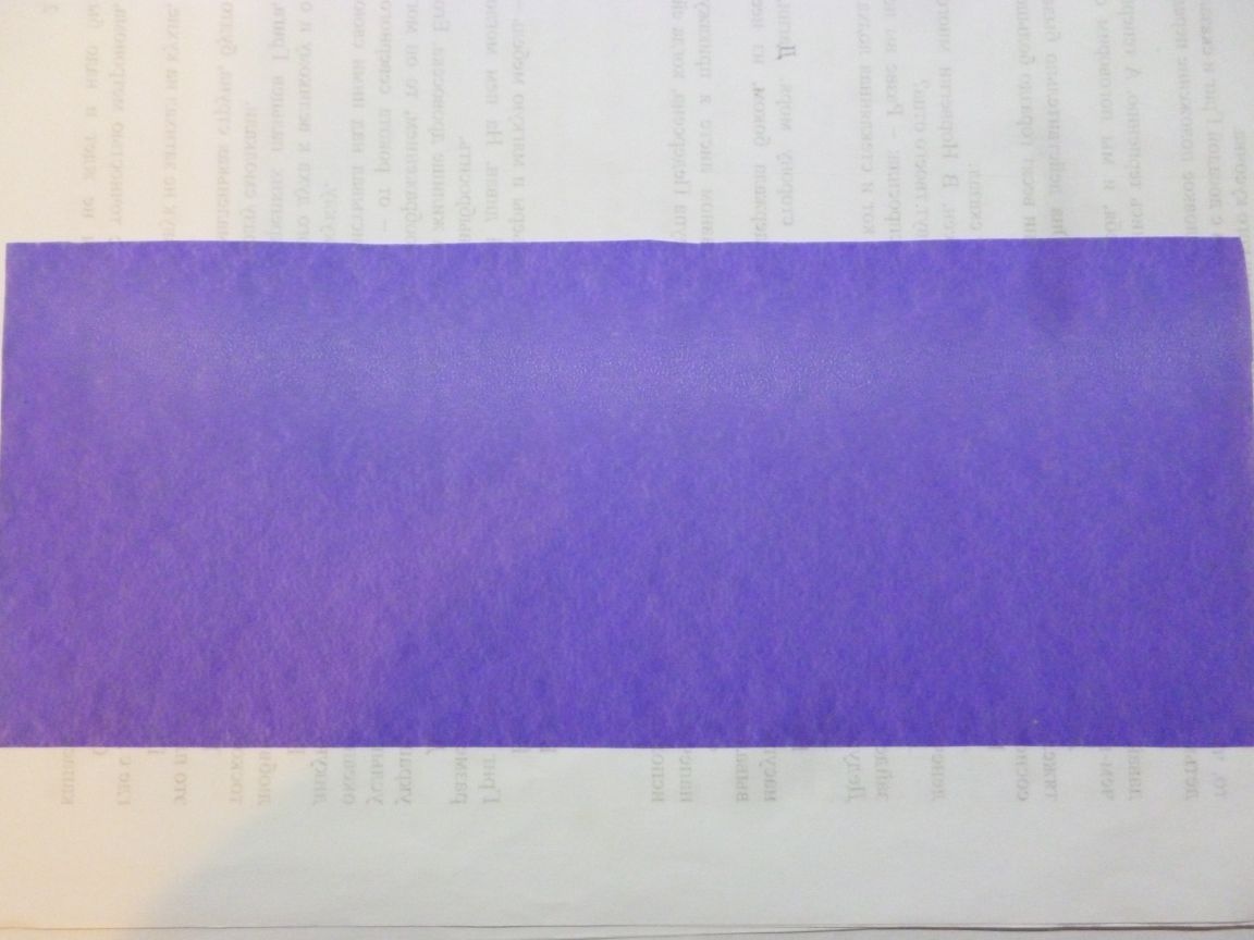
Let's start collecting everything. LEDs are very bright, and they do not look very aesthetically pleasing. If you used matte plastic, then there are no problems, but if the plastic is transparent, like mine, you will have to make a light filter. There are many options, the simplest is to take a sheet of white paper, cut a rectangle of the right size, make holes and put it on with plastic. I used the daddy tape I had.
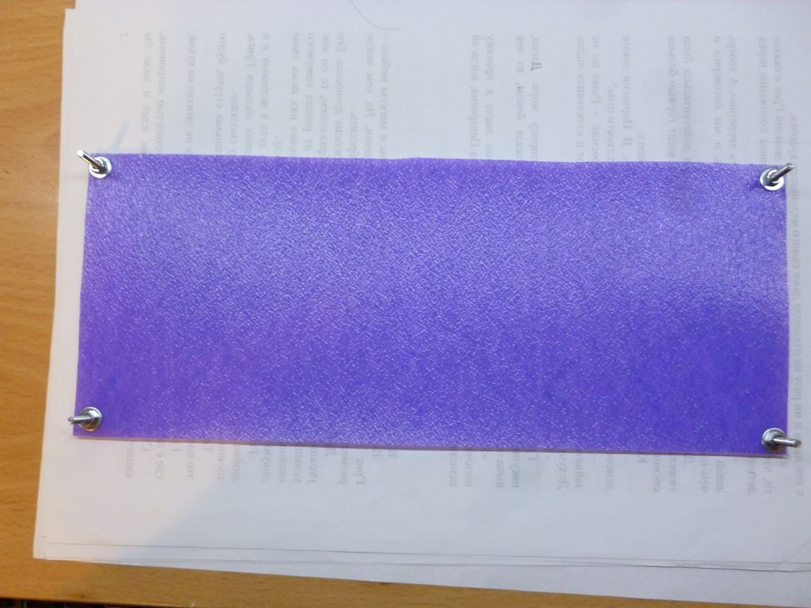
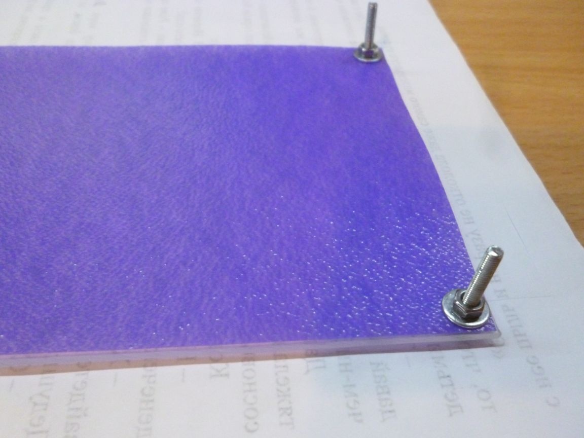
First, insert the bolts into our transparent rectangle, put on the light filter on the back side, then the washers and tighten with nuts.
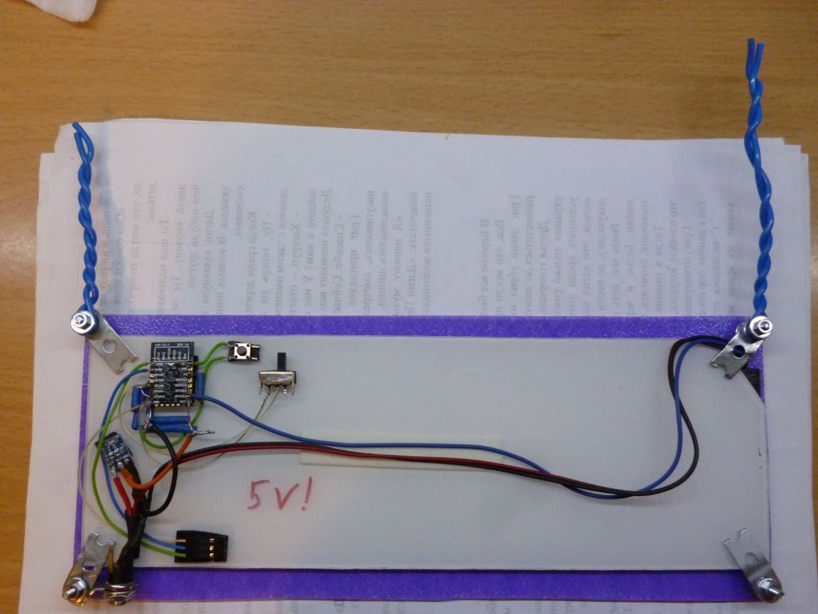
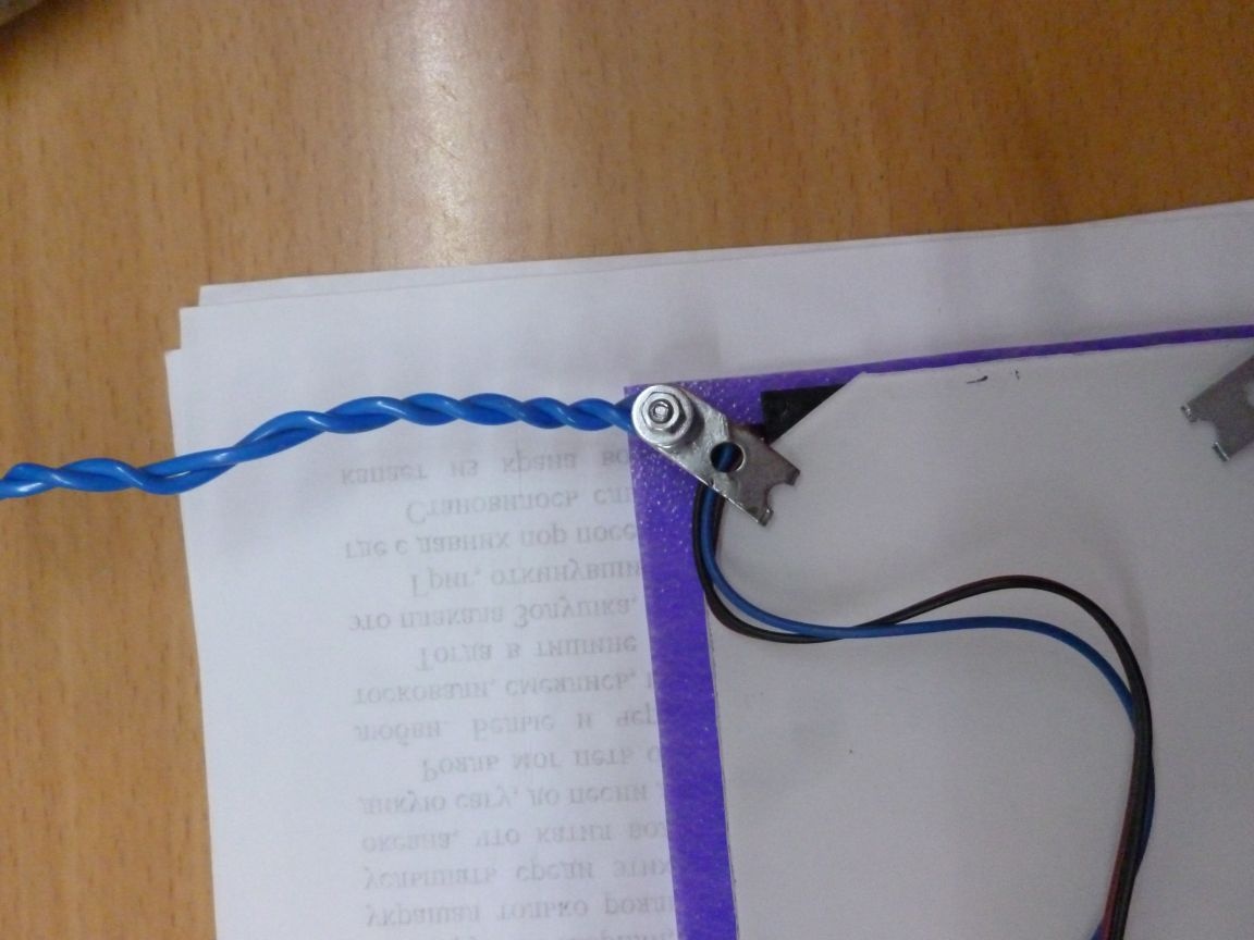
We install our base with LEDs down. For fixation, I used metal plates from a children's iron constructor. We fasten them with nuts on our bolts. Instead, you can use a wire bent into a loop. Or cut out plastic mounts.
As a result, we obtain the following construction:
We make loops of wire so that our watches can be broadcast.
Step 4 nutrition
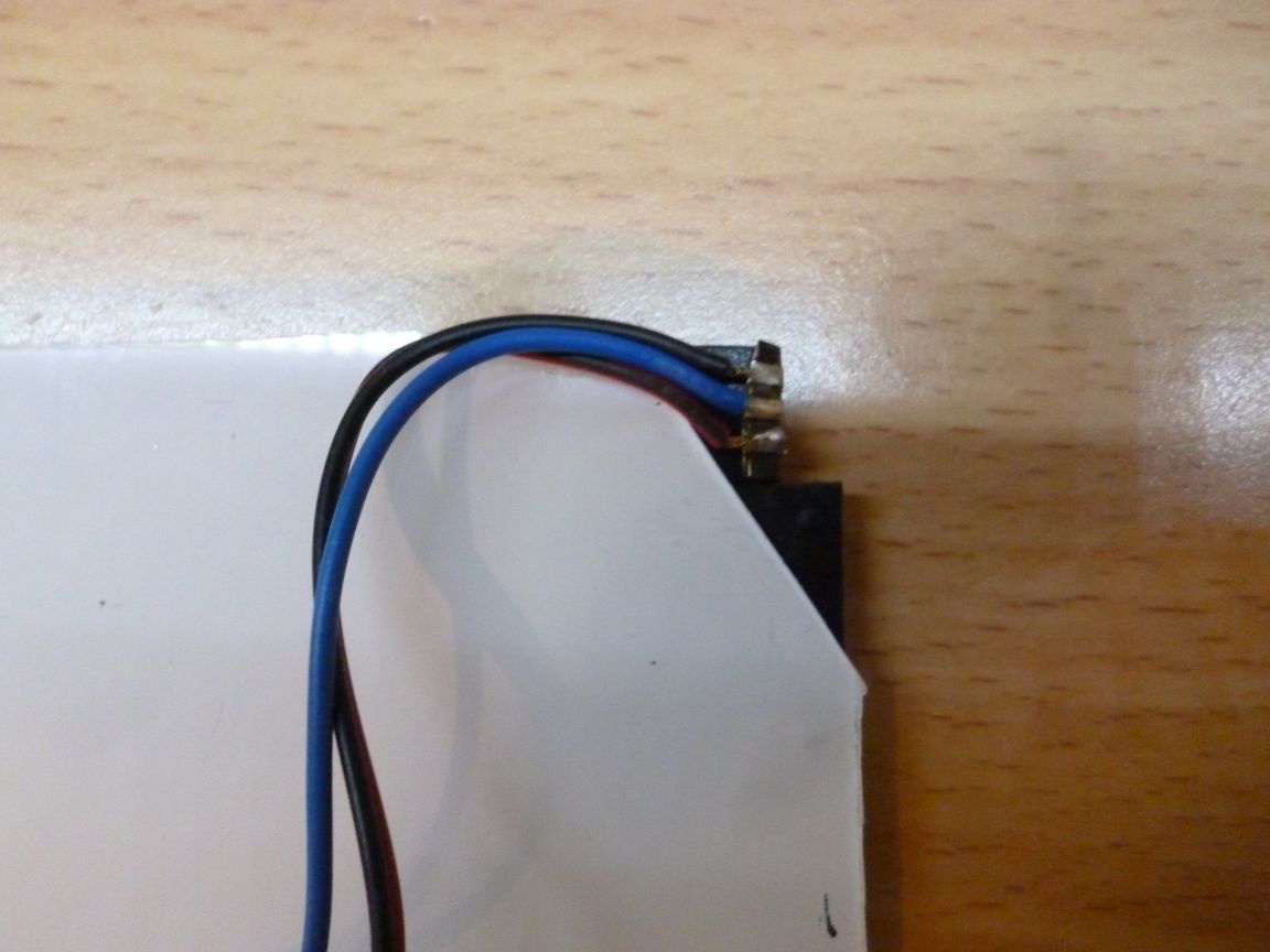
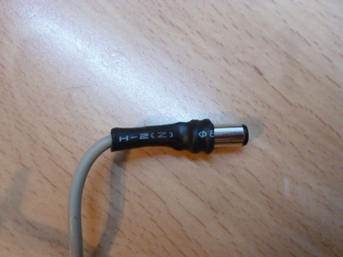
The WS2812 LED strip is powered by 5 volts. Therefore, for power, we need a stabilized power supply of 5 volts. I remind you that all actions must be performed on a device disconnected from the network. I use a redesigned phone charger. You need to cut off the wire at the plug for the phone, strip the wires and solder our plug to them. Red wire - plus solder to the center, black - minus to the external contact. Isolate.
Step 5 firmware
To write the firmware I use Arduino IDE with the add-on for ESP installed. We switch the clock to firmware mode and load our firmware. Do not forget to reboot the ESP 8266 before uploading the firmware. After starting, since the access point to which you want to connect is not specified, ESP will become the access point itself. We are connected to a new point. If you use a computer for access, the clock will be visible in the network infrastructure. Double-click and get to the clock settings. If you use the phone, then through the browser we type 192.168.1.1 and we see the web-interface for setting the clock. Here you can enter the time manually, specify the access point to which you want to connect, as well as the name of the clock and the name and password of the access point that the ESP raises. All changes, except time, take effect after a reboot. You can also restart the module via the web interface.