

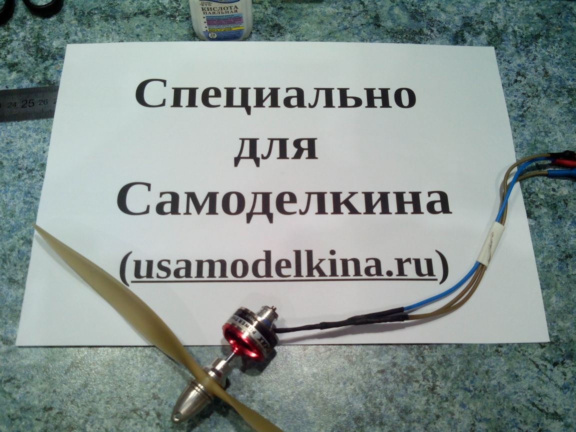
This article describes in detail the process of rewinding an electric brushless motor in home conditions. At first glance, this process may seem time-consuming and long, but if you look, then one rewind of the engine will take no more than an hour.
Engine rewound
Materials:
- Wire (0.3 mm)
- Varnish
- Shrink (2 mm and 5 mm)
Instruments:
- scissors
- Nippers
- soldering iron
- Solder and acid
- Sandpaper (file)
- Lighter
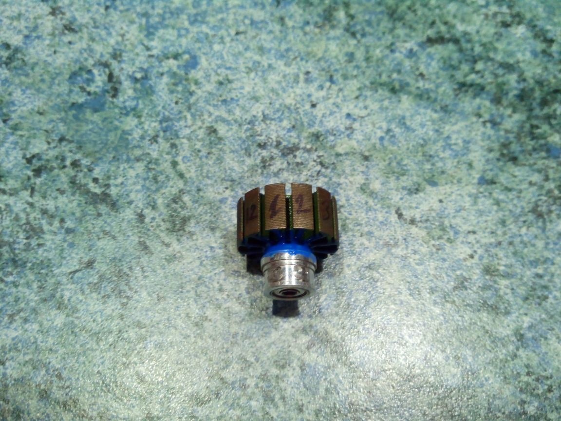
Step 1. Preparation of the motor and wire.
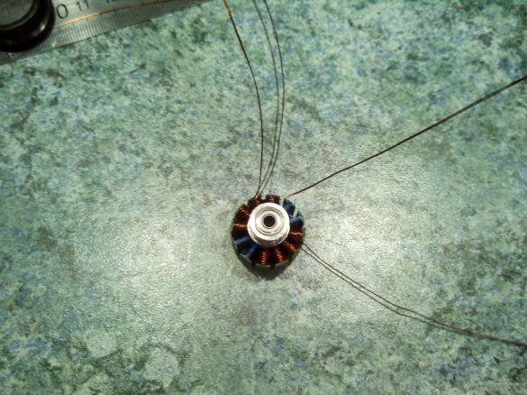
Remove the lock washer from the motor shaft and remove the stator.
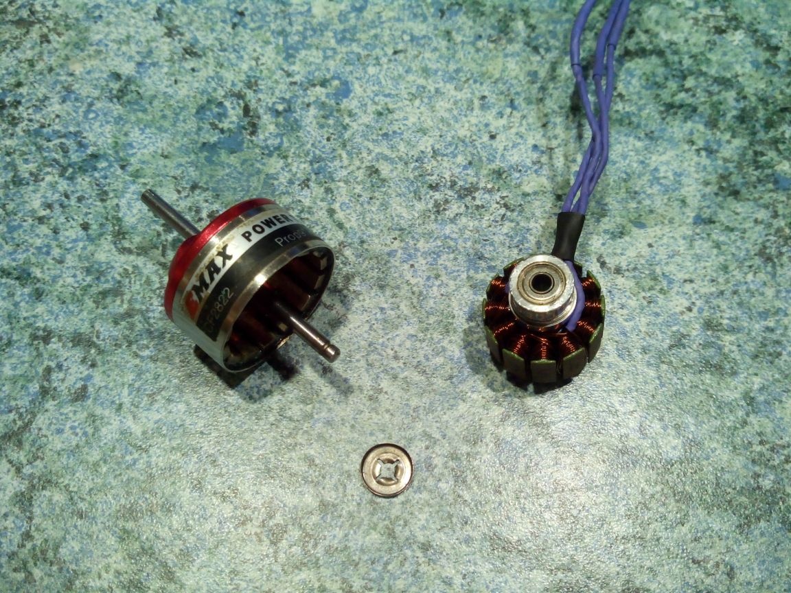
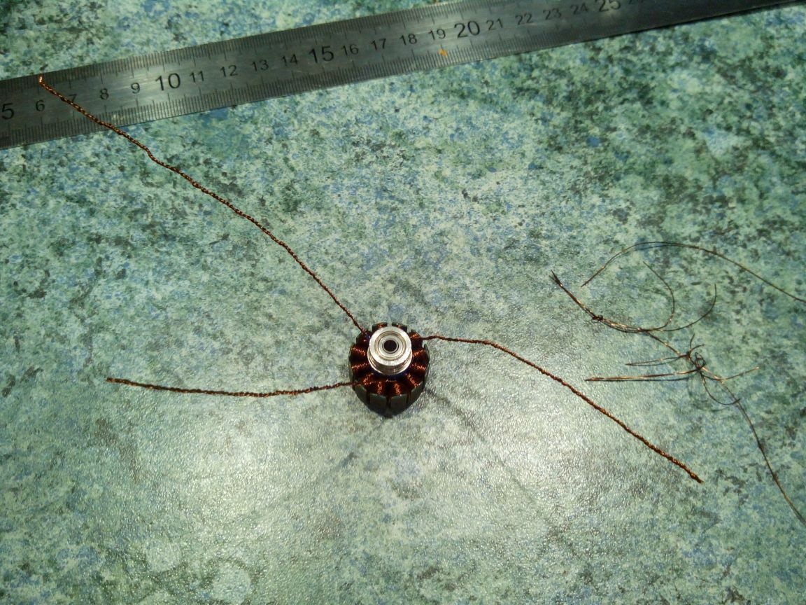
We wind the old winding from the stator. I recommend counting the number of turns on one tooth. The diameter of the old wire can be found by winding 10 turns on a pencil, measure the width of this winding with a ruler and divide by 10.
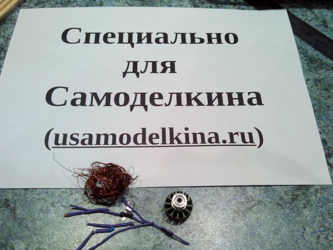
We carefully examine the stator's teeth for abrasions of the protective enamel. If necessary, gloss them with varnish (you can even nail polish).
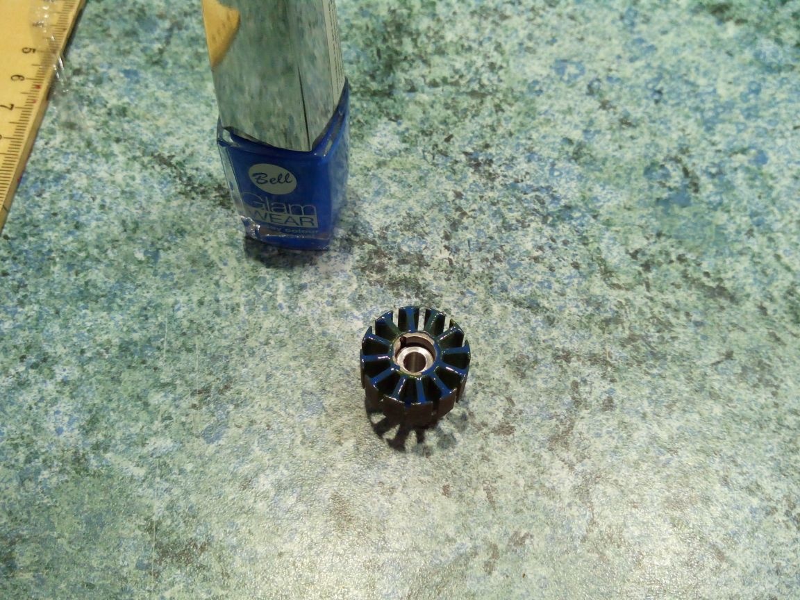
We use a felt-tip pen or marker for the disks to number the stator teeth so as not to mix and wind the wire on the wrong tooth.
In this case, a wire with a diameter of 0.3 mm will be wound in two cores of 16 turns per tooth. This is approximately 50 cm of double-folded wire per tooth + 20 cm to the findings.
Since one wire is wound around 4 teeth with two leads, and there are only 12 teeth, we need three double wires about 2.5 meters long. Better let it be with a margin than not enough pairs of turns for the last tooth.
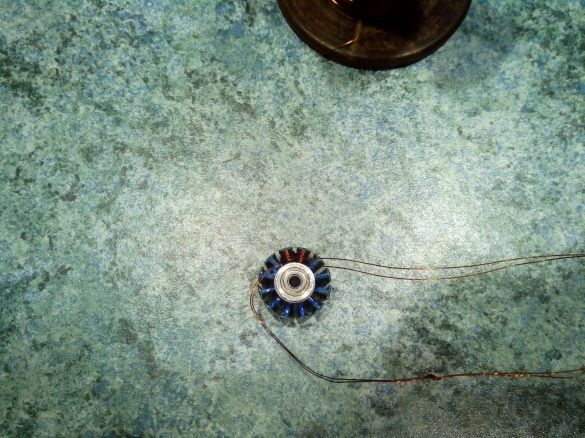
Step 2. Winding the stator teeth.
Winding will be divided into three stages, according to the number of wires. In order not to get confused in the conclusions of the wires, you can mark them with pieces of electrical tape or patch with inscriptions.
I deliberately do not attach separate photos of each wrapped tooth - they will say much more and show color schemes.
Wire number 1:
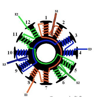
Winding pattern
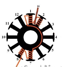
Leave about 10 cm of wire to create the output (S1).
We wind the first wire (in the diagram - Orange) per tooth №2 clockwise arrow. The denser and smoother the turns, the more turns the stator will fit on the teeth.
After winding 16 turns, lay the wire to the tooth №1 and wrap counter-clockwise arrows are also 16 turns.
Then we extend the wire to the tooth №7 and wrap 16 turns clockwise arrow.
Then we lay the wire to the tooth №8 and wrap 16 turns counter-clockwise arrows.
Leave 10 cm of wire to create the output (E1), the rest can be cut off.
That's it, the first wire is wound.
Wire number 2:
Leave about 10 cm of wire to create the output (S1).
We wind the first wire (in the diagram - Orange) per tooth №2 clockwise arrow. The denser and smoother the turns, the more turns the stator will fit on the teeth.
After winding 16 turns, lay the wire to the tooth №1 and wrap counter-clockwise arrows are also 16 turns.

Then we extend the wire to the tooth №7 and wrap 16 turns clockwise arrow.
Then we lay the wire to the tooth №8 and wrap 16 turns counter-clockwise arrows.
Leave 10 cm of wire to create the output (E1), the rest can be cut off.
That's it, the first wire is wound.
Wire number 2:
Winding pattern
Leave about 10 cm of wire to create the output (S2).
We wind 16 turns of the second wire (in the diagram - green) per tooth №6 clockwise arrow.
Lay the wire to the tooth №5 and wrap 16 turns counter-clockwise arrows.
Then we extend the wire to the tooth №11 and wrap 16 turns clockwise arrow.
Then we lay the wire to the tooth №12 and wrap 16 turns counter-clockwise arrows.
Leave 10 cm of wire to create the output (E2), cut off the rest.
The second wire is wound.
Wire number 3:
Leave about 10 cm of wire to create the output (S2).
We wind 16 turns of the second wire (in the diagram - green) per tooth №6 clockwise arrow.
Lay the wire to the tooth №5 and wrap 16 turns counter-clockwise arrows.
Then we extend the wire to the tooth №11 and wrap 16 turns clockwise arrow.
Then we lay the wire to the tooth №12 and wrap 16 turns counter-clockwise arrows.
Leave 10 cm of wire to create the output (E2), cut off the rest.
The second wire is wound.

Wire number 3:
Winding pattern
Leave about 10 cm of wire to create the output (S3).
We wind 16 turns of the second wire (in the diagram - blue) per tooth №10 clockwise arrow.
Lay the wire to the tooth №9 and wrap 16 turns counter-clockwise arrows.
Then we extend the wire to the tooth №3 and wrap 16 turns clockwise arrow.
Then we lay the wire to the tooth №4 and wrap 16 turns counter-clockwise arrows.
Leave 10 cm of wire to create the output (E3), cut off the rest.
The third wire is wound.
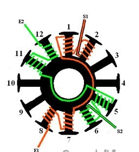
Step 3. Connection of the winding leads.
Leave about 10 cm of wire to create the output (S3).
We wind 16 turns of the second wire (in the diagram - blue) per tooth №10 clockwise arrow.
Lay the wire to the tooth №9 and wrap 16 turns counter-clockwise arrows.
Then we extend the wire to the tooth №3 and wrap 16 turns clockwise arrow.
Then we lay the wire to the tooth №4 and wrap 16 turns counter-clockwise arrows.
Leave 10 cm of wire to create the output (E3), cut off the rest.
The third wire is wound.
Step 3. Connection of the winding leads.
Connection diagram
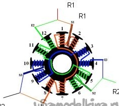
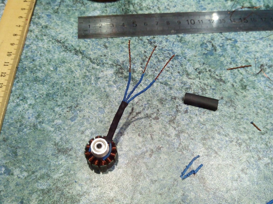
Conclusion S1 and E2 (teeth №2 and №12) twist at the base of the teeth, making a tail 5-7 cm long.
Similarly, twist the findings of S2 and E3 (teeth №6 and №4), as well as the findings of S3 and E1 (teeth №10 and №8)

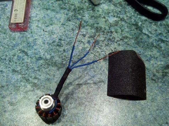
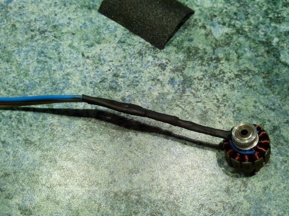
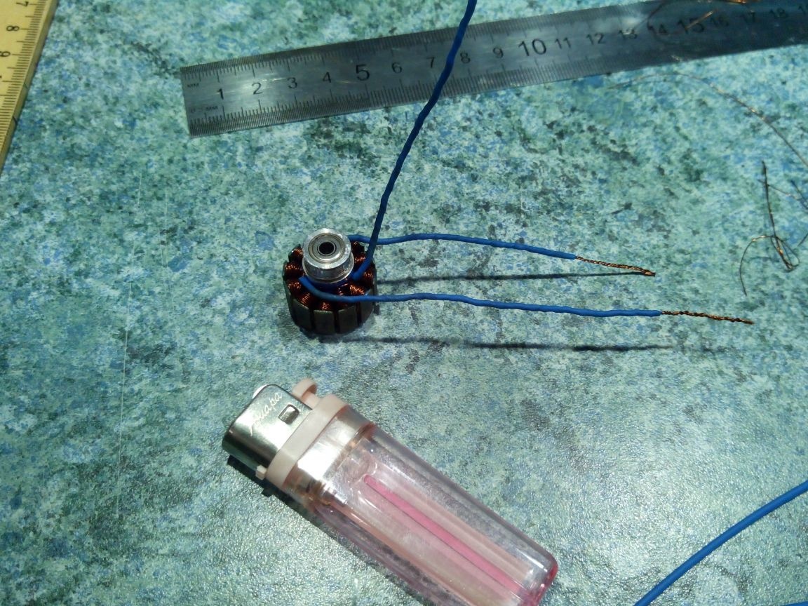
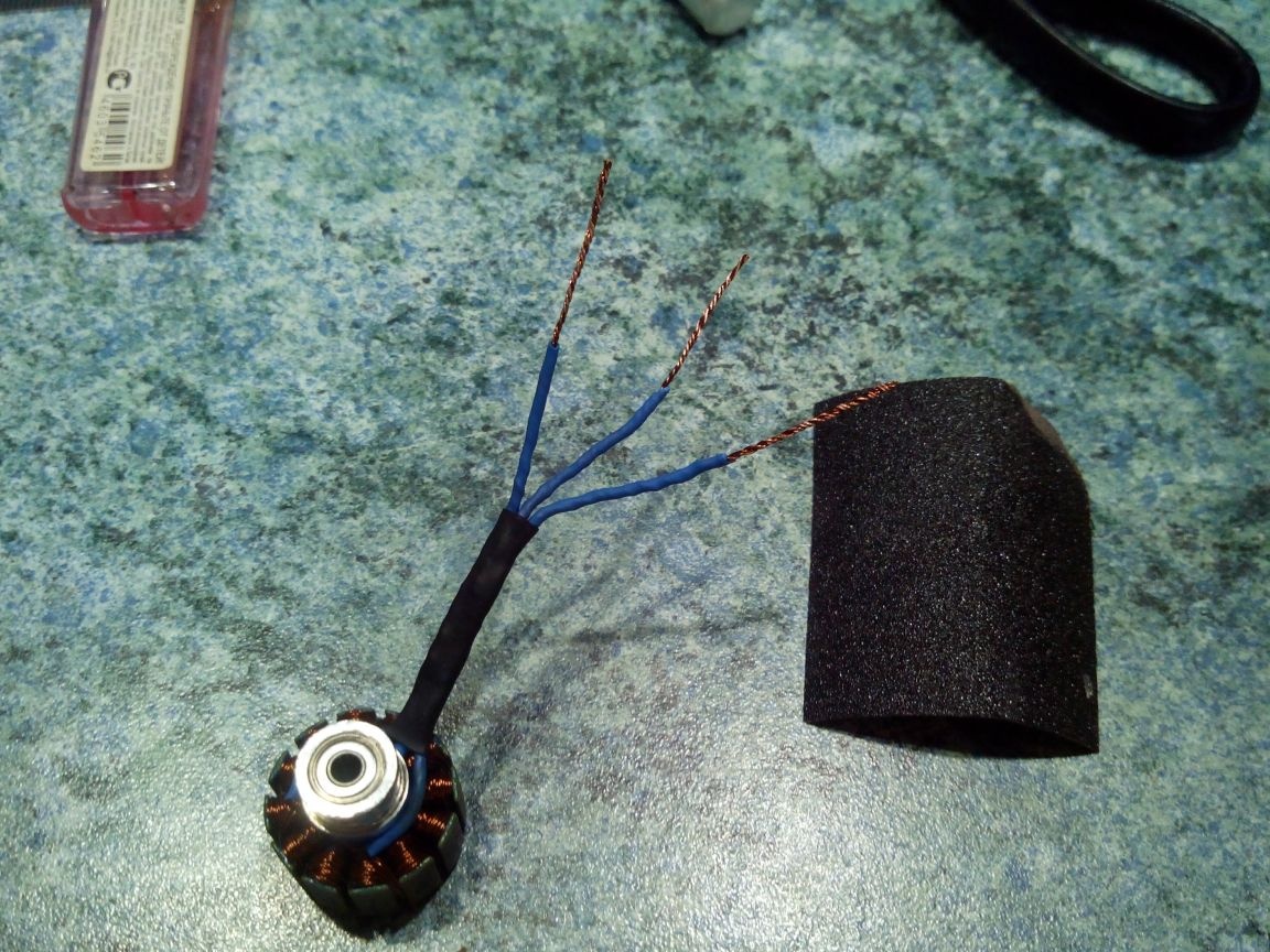
Thin heat shrink along the entire length and to the very bottom we pull on the findings. Then gently heat it with a lighter.
We collect the resulting three conclusions together and pull together a shrink of a larger diameter, pulling it also to the very base.

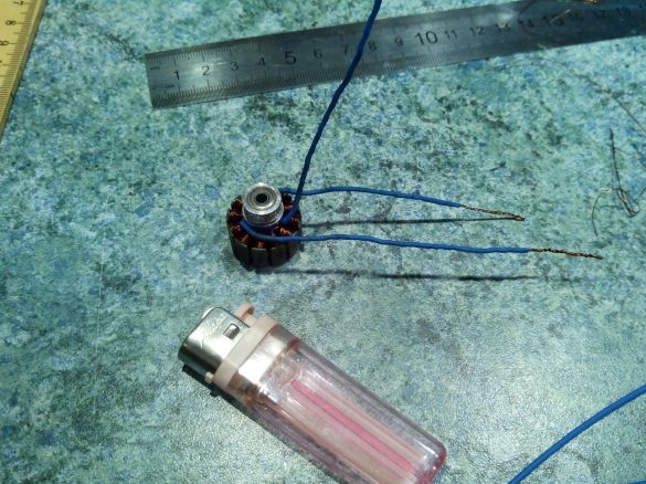
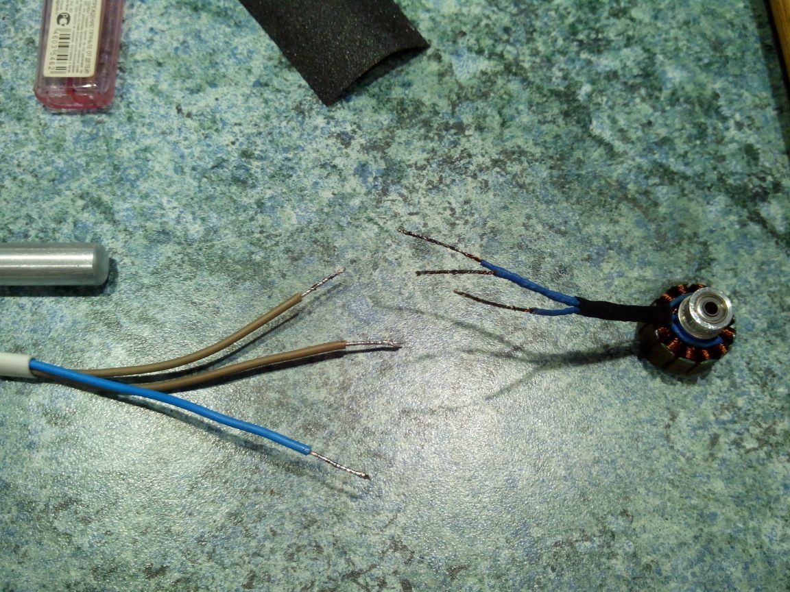
Step 4. Soldering the connectors.
We clean the ends of the conclusions with sandpaper or a file.
Using a soldering iron using soldering acid, we tack the ends of the terminals and the ends of the wires with connectors.

We solder the wires, close them individually with heat shrink, and then we pull all the wires together with another heat-shrink tubing.
We insert the stator into the rotor and fix it with a lock washer.

Everything, the engine is ready. It remains only to connect it to the regulator and the battery and check.
Conclusion S1 and E2 (teeth №2 and №12) twist at the base of the teeth, making a tail 5-7 cm long.
Similarly, twist the findings of S2 and E3 (teeth №6 and №4), as well as the findings of S3 and E1 (teeth №10 and №8)
Thin heat shrink along the entire length and to the very bottom we pull on the findings. Then gently heat it with a lighter.
We collect the resulting three conclusions together and pull together a shrink of a larger diameter, pulling it also to the very base.
Step 4. Soldering the connectors.
We clean the ends of the conclusions with sandpaper or a file.
Using a soldering iron using soldering acid, we tack the ends of the terminals and the ends of the wires with connectors.
We solder the wires, close them individually with heat shrink, and then we pull all the wires together with another heat-shrink tubing.

We insert the stator into the rotor and fix it with a lock washer.
Everything, the engine is ready. It remains only to connect it to the regulator and the battery and check.