» Electronics » Power supplies »Power supply 1 ... 20 V with current protection

Power supply 1 ... 20 V with current protection


When setting up various electronic devices requires a power supply unit (PSU), in which there is an adjustment of the output voltage and the ability to control the level of operation of the protection against overcurrent over a wide range. When the protection is activated, the load (connected device) should be automatically disconnected.

A search on the Internet gave several suitable power supply circuits. He stopped at one of them. The circuit is easy to manufacture and commission, consists of accessible parts, fulfills the stated requirements.

The power supply proposed for manufacture is based on the operational amplifier LM358 and has the following characteristics:
Input voltage, V - 24 ... 29
Output stabilized voltage, V - 1 ... 20 (27)
Protection operation current, A - 0.03 ... 2.0


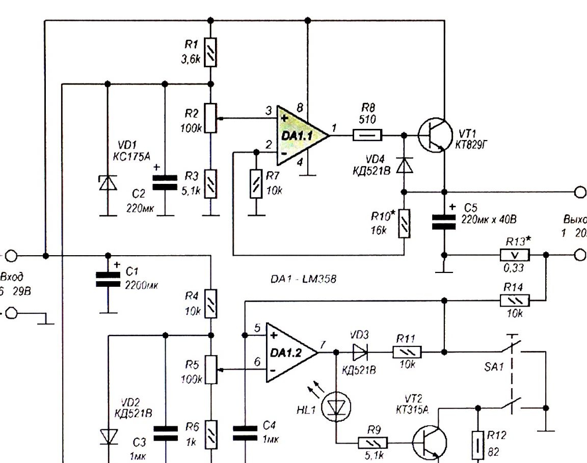
Photo 2. Power supply circuit


An adjustable voltage regulator is assembled on an operational amplifier DA1.1. The amplifier input (terminal 3) receives the model voltage from the engine of the variable resistor R2, the zener diode VD1 is responsible for its stability, and the voltage is supplied to the inverting input (terminal 2) from the emitter of the transistor VT1 through the voltage divider R10R7. Using a variable resistor R2, you can change the output voltage of the PSU.
The overcurrent protection unit is made on the operational amplifier DA1.2, it compares the voltage at the inputs of the op-amp. Input 5 through resistor R14 receives voltage from the load current sensor - resistor R13. The inverting input (pin 6) receives an exemplary voltage, for the stability of which the VD2 diode with a stabilization voltage of about 0.6 V is responsible.

While the voltage drop created by the load current on the resistor R13 is less than the exemplary, the output voltage (pin 7) of the DA1.2 op amp is close to zero. In the event that the load current exceeds the permissible set level, the voltage at the current sensor will increase and the voltage at the output of the op amp DA1.2 will increase almost to the supply voltage. In this case, the HL1 LED turns on, signaling the excess, the transistor VT2 opens, bypassing the Zener diode VD1 with the resistor R12. As a result, the transistor VT1 closes, the output voltage of the PSU decreases almost to zero and the load switches off. To turn on the load, press the button SA1. The protection level is adjusted using a variable resistor R5.

BP manufacturing

1. The basis of the power supply, its output characteristics are determined by the current source - the used transformer. In my case, a toroidal transformer from a washing machine was used. The transformer has two output windings on 8v and 15v. By combining both windings in series and adding a rectifier bridge on the KD202M medium power diodes at hand, I got a DC voltage source 23v, 2a for a power supply.


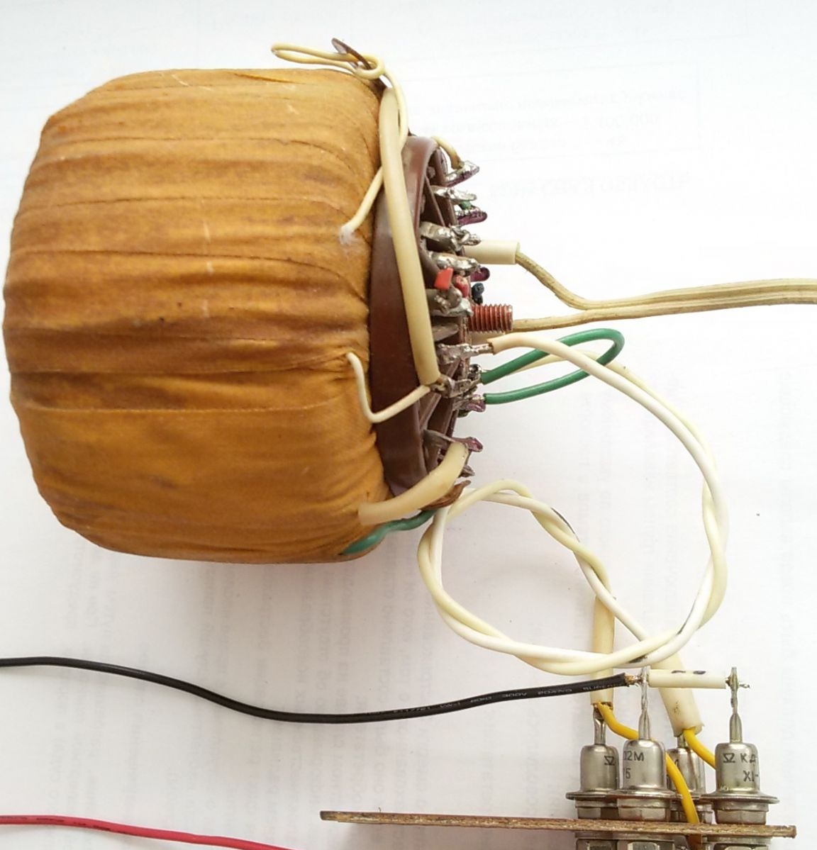
Photo 3. Transformer and rectifier bridge.

2. Another determining part of the PSU is the instrument body. In this case, a children's slide projector interfering in the garage. Having removed the excess and having processed in the front of the hole to install the indicating microammeter, we obtained a blank for the PSU case.


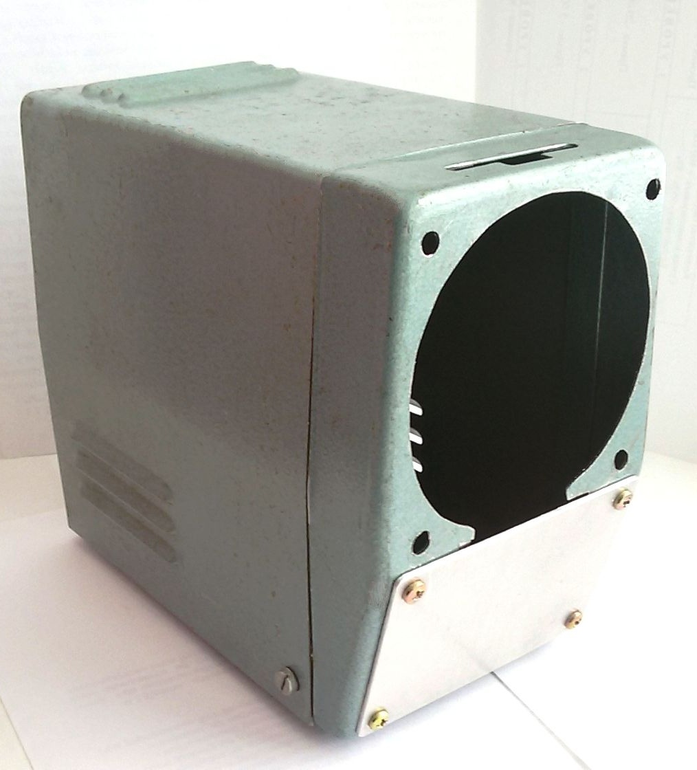
Photo 4. BP case blank

3. The electronic circuit was mounted on a universal mounting plate measuring 45 x 65 mm. The layout of the parts on the board depends on the dimensions found in the component farm. Instead of resistors R6 (setting the operating current) and R10 (limiting the maximum output voltage), trim tab resistors with a 1.5 times larger nominal value are installed on the board. At the end of the PSU settings, they can be replaced by permanent ones.


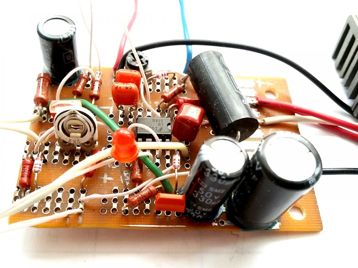
Photo 5. Mounting plate

4. The assembly of the circuit board and external elements of the electronic circuit in full for testing, tuning and adjusting the output parameters.


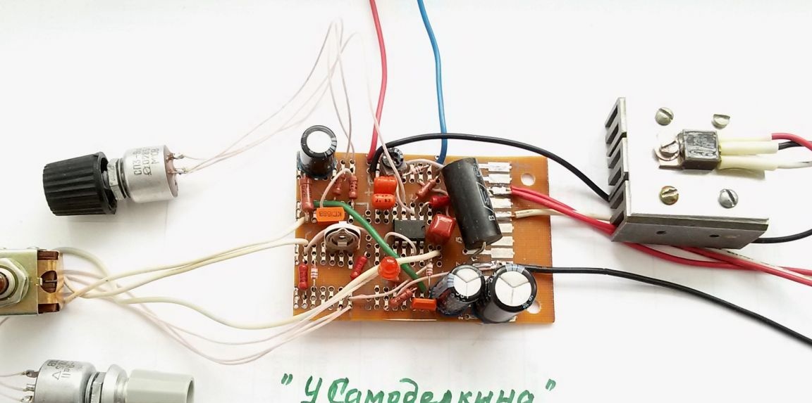
Photo 6. PSU control unit

5. Fabrication and adjustment of the shunt and additional resistance to use a microammeter as an ammeter or a BP voltmeter. Additional resistance consists of series-connected constant and tuning resistors (pictured above). A shunt (pictured below) is included in the main current circuit and consists of a wire with low resistance. The wire cross section is determined by the maximum output current. When measuring the current strength, the device is connected parallel to the shunt.


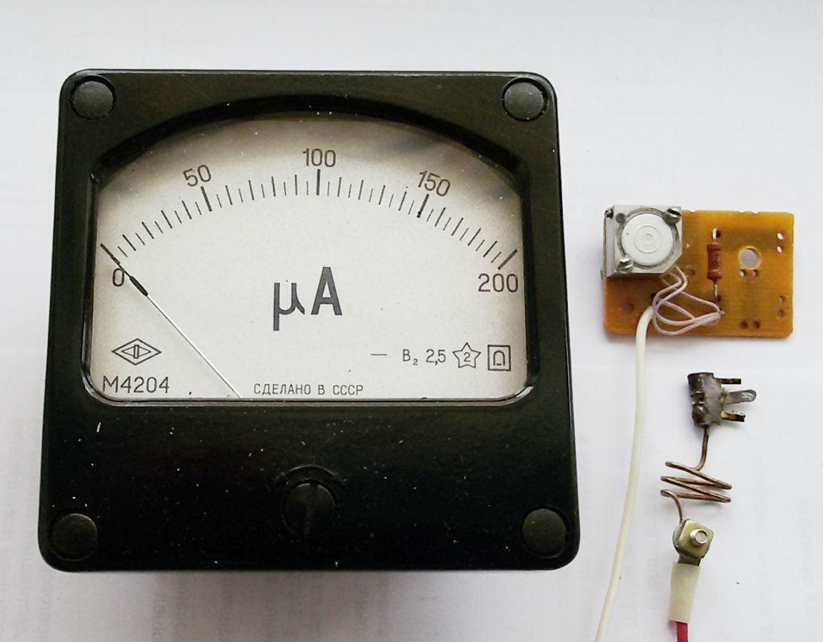
Photo 7. Microammeter, shunt and additional resistance

Adjustment of the length of the shunt and the value of the additional resistance is carried out with an appropriate connection to the device with monitoring for compliance with a multimeter. Switching the device to the Ammeter / Voltmeter mode is performed by the toggle switch in accordance with the scheme:

Power supply 1 ... 20 V with current protection

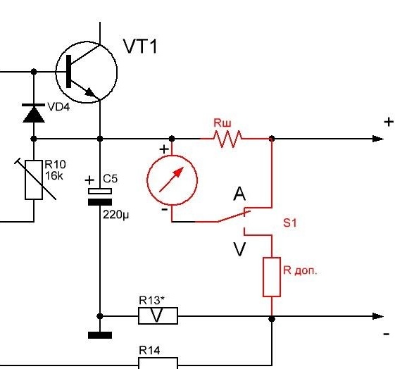
Photo 8. Scheme of switching the control mode

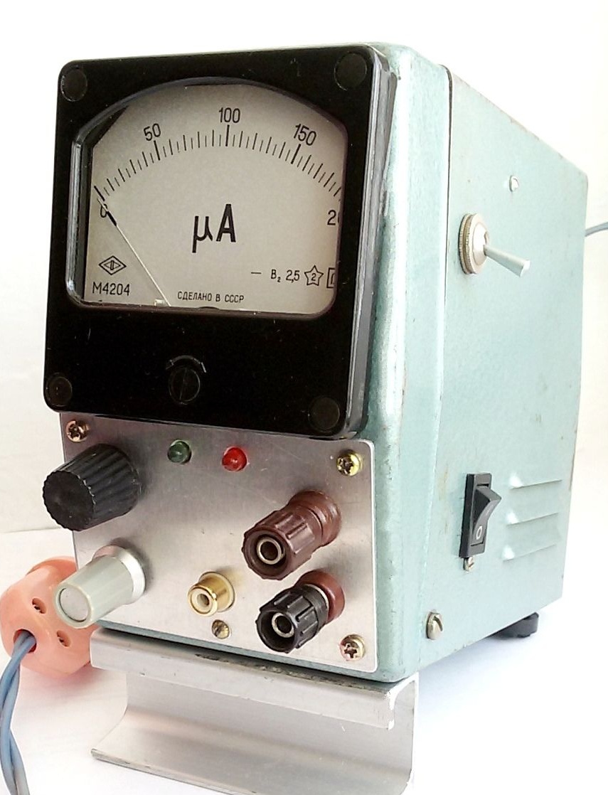
6. Marking and processing of the front panel of the PSU, installation of remote parts. In this embodiment, a microammeter is placed on the front panel (toggle switch for A / V control mode to the right of the device), output terminals, voltage and current regulators, operation mode indicators. To reduce losses and in connection with frequent use, a separate stabilized 5-volt output is additionally output. For this, the voltage from the transformer winding to 8V is supplied to the second rectifier bridge and a typical circuit at 7805 with built-in protection.


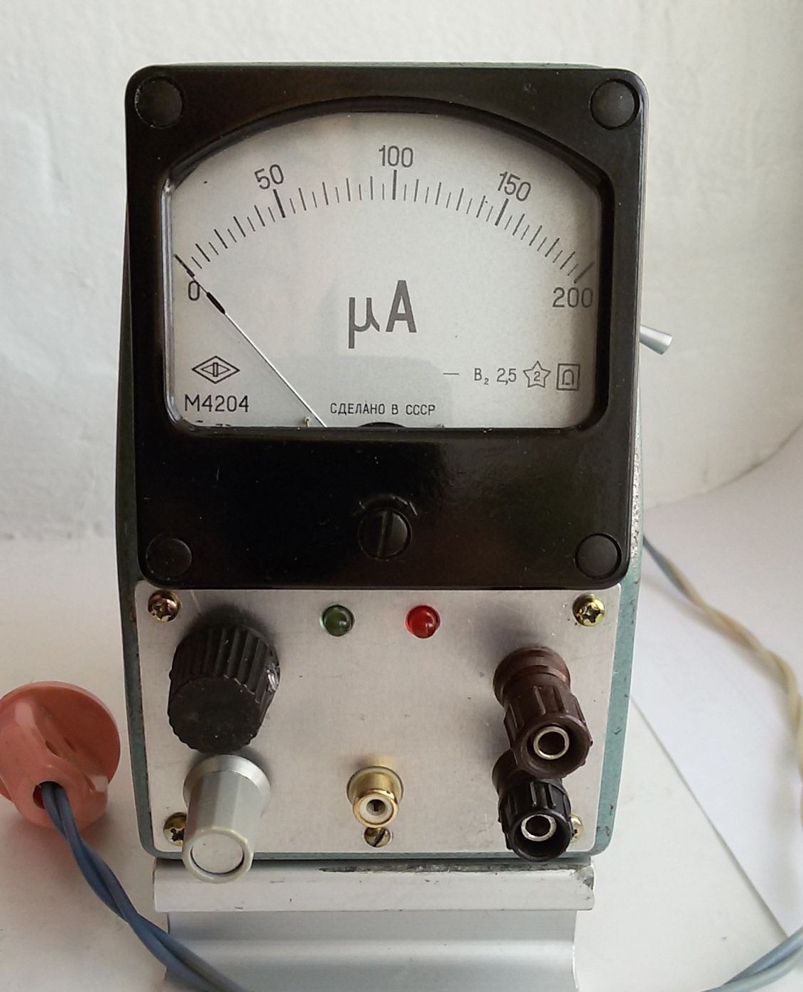
Photo 9. Front panel

7. Assembly of the power supply. All power supply elements are installed in the housing. In this embodiment, the radiator of the control transistor VT1 is an aluminum plate 5 mm thick, mounted in the upper part of the housing cover, which serves as an additional radiator. The transistor is mounted on the radiator through an electrically insulating gasket.


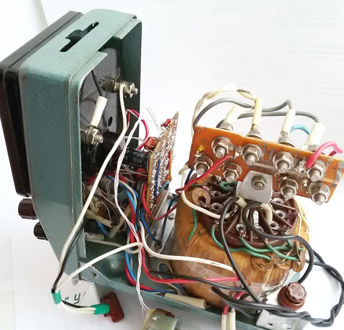
Photo 10. Assembling a PSU without a cover


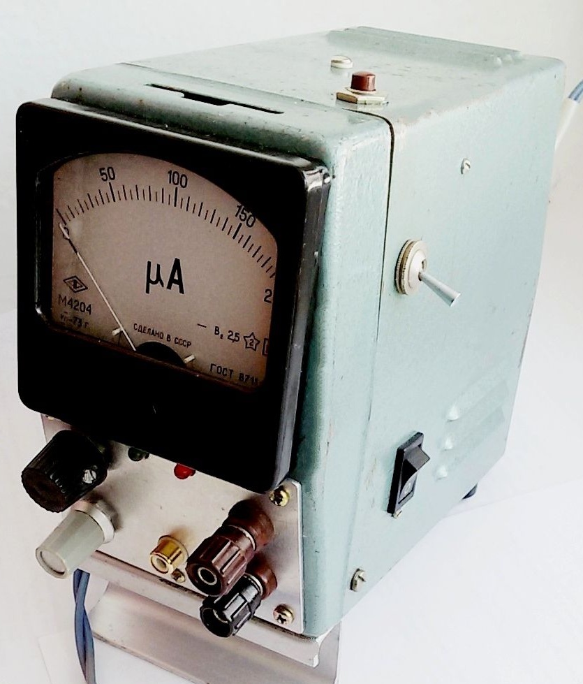
Photo 11. General view of the power supply.

Details:

The operational amplifier LM358N incorporates two op-amps.

Transistor VT1 can be replaced with any of the series КТ827, КТ829. Transistor VT2 any of the KT315 series. The Zener diode VD1 can be used by anyone with a stabilization voltage of 6.8 ... 8.0V and a current of 3 ... 8 mA. VD2-VD4 diodes from the KD521 or KD522B series. Capacitors C3, C4 - film or ceramic. Oxide capacitors: C1 - K50-18 or similar imported, the rest - from the K50-35 series. Fixed resistors of the MLT series, variables - SP3-9a.

Establishing a power supply - the variable resistor R2 engine is moved to the upper position according to the scheme and the maximum output voltage is measured, set to 20 V, selecting resistor R10. After that, the load is connected to the output and measurements of the protection operation current are made. To reduce the level of protection operation, reduce the resistance of the resistor R6. To increase the maximum level of protection operation, reduce the resistance of the resistor R13 - load current sensor.
9.2
8.4
7.8

Add a comment

    • smilesmilesxaxaokdontknowyahoonea
      bossscratchfoolyesyes-yesaggressivesecret
      sorrydancedance2dance3pardonhelpdrinks
      stopfriendsgoodgoodgoodwhistleswoontongue
      smokeclappingcraydeclarederisivedon-t_mentiondownload
      heatirefullaugh1mdameetingmoskingnegative
      not_ipopcornpunishreadscarescaressearch
      tauntthank_youthisto_clueumnikacuteagree
      badbeeeblack_eyeblum3blushboastboredom
      censoredpleasantrysecret2threatenvictoryyusun_bespectacled
      shokrespektlolprevedwelcomekrutoyya_za
      ya_dobryihelperne_huliganne_othodifludbanclose
19 comments
Author
Thank you for the offer, I agree with you.
So, I drew something. I think you will understand.
Quote: lihvin
Although, if you transfer the connection points of the device for a shunt (in voltage mode), then this "problem" will be solved.
In this case, the arrow of the device in the (Ammeter) mode will go in the negative direction.

No matter where she goes, I thought you could solve it yourself. Put a little more complicated switch and the whole business then. Instead of 3 legs, 6 pins, medium per device. The same type is possible, only 6.
Author
Although, if you transfer the connection points of the device for a shunt (in voltage mode), then this "problem" will be solved.
In this case, the arrow of the device in the (Ammeter) mode will go in the negative direction.
The important thing is not loss of electricity, they are really insignificant, but an increase in the output resistance of the voltage source, and, therefore, an increase in the dependence of the output voltage on the current.
A simple example. They set the output voltage to 10 V without load, then connected the load taking 1A, for example, a 10 Ohm resistor.
If Rout = 0, then the output voltage has not changed.
If Rout = 0.33 (addition from a current-measuring shunt), then the output voltage became 9, 67 V.
If there is a simple opportunity to make the device more accurate, then why not use it?
Each change in the load current leads to a reaction of the source and a change in its voltage, which, in turn, leads to a corresponding change in current, that is, there is a slight fluctuation in the supply voltage to calm down.
Although, if you transfer the connection points of the device for a shunt (in voltage mode), then this "problem" will be solved.
Quote: Ivan_Pokhmelev
Less current loss, more precisely maintaining the output voltage.

Come on?! Is it so important for this appliance? Anyway, plus or minus 75mV will play a significant role in business?
Less current loss, more precisely maintaining the output voltage.
Quote: Ivan_Pokhmelev
Quote: lihvin
And I did not dare to hang the device on the current sensor (with an additional body kit), fearing the mutual influence of the device, additional. resistance and current protection regulator.

And in vain. That is exactly what you had to do.

And what is the problem actually? What does this give, what is the advantage?
Quote: lihvin
And I did not dare to hang the device on the current sensor (with an additional body kit), fearing the mutual influence of the device, additional. resistance and current protection regulator.

And in vain. That is exactly what you had to do.
Author
[quote = Ivan_Pokhmelev] If you do not understand what is at stake, answer at least these questions: what is the resistance of Rш and the head of a microammeter.

Thank you for the offer, but I can also calculate Rш according to the formula, but after the calculation, it is still necessary to adjust the shunt under the microammeter (checked repeatedly). I was just lucky and no calculations were needed, because in 10 minutes I was able to select (controlling by the tester) the necessary length of the shunt from the older length (see photo 7). And I did not dare to hang the device on the current sensor (with an additional body kit), fearing the mutual influence of the device, additional. resistance and current protection regulator.
If you do not understand what is at stake, answer at least these questions: what is the resistance of Rш and the head of the microammeter.
And R13 is selected due to, as you rightly pointed out Pronin, the wrong choice opamp.
Author
Quote: Ivan_Pokhmelev

2. How is it a “single shunt”, huh? R13 - what do you think? It is necessary to remove the voltage for the ammeter from it.

Resistor R13 is a current sensor and is selected - (*)! for stable operation of the overcurrent protection unit in the range of 0.03 ... 2.0A. (Description of the BP. - only 17 lines).
And the shunt, as you know, is adjusted to the existing microammeter.
Different goals - different resistors.
Today I complete (found the case) a new one. I decided to use electronic blocks ready with Ali.
Indicator in one,
current and voltage ...
The adjustment unit is 0.8-30 V 12A.

Transformer option. A cooler will be installed for cooling in automatic mode. I’ve already prepared everything, it remains to find time for the project.
I have a lot of questions for this home-made product both in design and in the scheme (some of them have already been voiced), and ...
For example, the rationality of using a voltage of 20 volts at a current of 2A ?!
Does such a combination occur at all? Personally, I decided to make a ready-made power supply unit (industrial design), expanding its capabilities. The unit produces an adjustable voltage of up to 15 volts, with a cut-off current of 1.5 A.

He expanded his capabilities, installed a current divider. Derived testimony A on the device
For a long time I also wanted to make a similar scheme. Only with a breakdown into 2 voltage ranges to reduce the voltage drop across the regulating transistor and, accordingly, the power dissipation.
According to this scheme, it can be noted that the current protection adjustment was unsuccessfully made. At the input of the LM358 op amp, voltages near 0 are applied (with unipolar op amp supply). For this mode, Rail-to-Rail op amps must be used, not general applications. And resistor R5 needs to be on the order of kOhm.
1. C'mon, the “second hand” - there the block width is not more than 80 mm, it is perfectly pressed with one hand if the button were on the right, besides, someone said:
the button is rarely used

2. How is it a “single shunt”, huh? R13 - what do you think? It is necessary to remove the voltage for the ammeter from it.
Author
Quote: Ivan_Pokhmelev

1. The reset button is not ergonomically located.
2. What is the second shunt for?


1. Another location of the reset button requires the use of a second hand to keep the PSU from shifting when the button is pressed, which is inconvenient. Pressing down eliminates this. The location of the button on the front panel will interfere with other elements. Since the button is rarely used, it is removed from the work area.
2. On add. the circuit has only one shunt - for an ammeter. There are no other shunts in the circuits.
1. The reset button is not ergonomically located.
2. What is the second shunt for?

We advise you to read:

Hand it for the smartphone ...