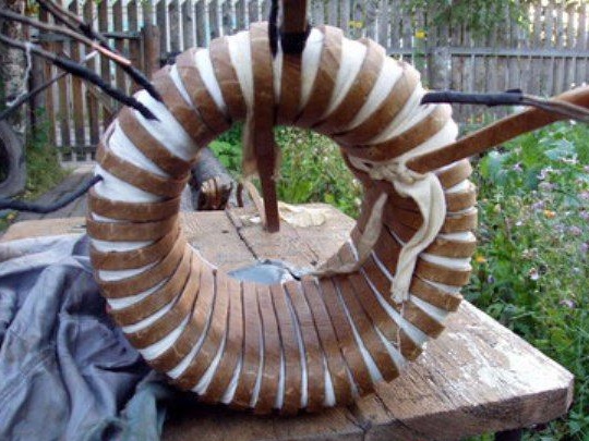
If you decide to do electric welding do it yourself, but don’t know how easy it is to do this, you can take a closer look at this project. Here the welding transformer is assembled from the motor stator. The design is good because almost everything is already available in the engine to create welding, you just need to make some improvements to the magnetic circuit and wrap the transformer correctly.
As for the technical characteristics, asynchronous motors with a capacity of about 4 kW are suitable for such purposes, they are often used at different enterprises.
Materials and tools for homemade:
- an electric motor with a capacity of 4 kW;
- wrenches, pliers, chisels, screwdrivers and other tools to disassemble the engine;
- kiper tape;
- sledgehammer.
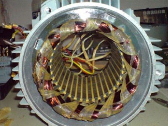
The process of manufacturing electric welding:
Step one. We disassemble the electric motor
According to the author, such an engine is quite easy to understand. You only need to stock up with wrenches. Using them, you need to unscrew a couple of nuts, which are pulled together by two engine covers with each other and the stator housing. If the engine is already rusty, then sometimes it is not so easy to unscrew these nuts, in which case you can use a grinder and just cut the studs. Well, after that you will need to use a hammer or sledgehammer to knock the covers off the engine.
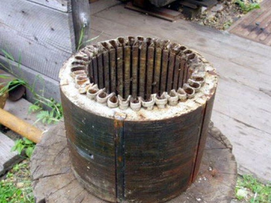
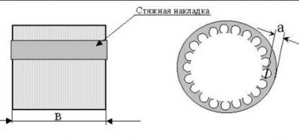
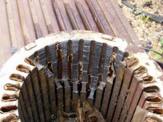
After disassembling, the rotor will need to be pulled out of the stator; it will not be needed for home-made work. The stator is a set of steel plates, they form a magnetic circuit. There is a winding on the magnetic circuit. The stator dimensions of the motors, as well as the geometry, may vary. To create electric welding, it is best to choose engines with a large diameter and a small length.
The magnetic core ring is of the greatest value in the stator; everything else will only interfere. The magnetic core is usually pressed into a cast iron or aluminum housing. The wires pass in the grooves of the magnetic circuit, they must be removed. This is best done when the magnetic circuit is still in the housing.To remove the wires, you need to take a chisel and chop them off at the end with a sharp chisel on one side of the stator. Well, then they can be pulled out in the form of loops with the help of pliers, having previously been pry off with a screwdriver.
To remove the wires was easier, they can be burned with a blowtorch. Just do not heat the metal of the magnetic circuit too much, otherwise it may lose its technical characteristics.
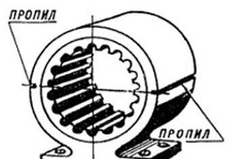
The cast iron body can be split with a sledgehammer. In order for it to split as it should, longitudinal cuts can be made on it. But in this matter, it is important not to overdo it, otherwise you can bend the magnetic circuit.
Step Two Magnetic core preparation
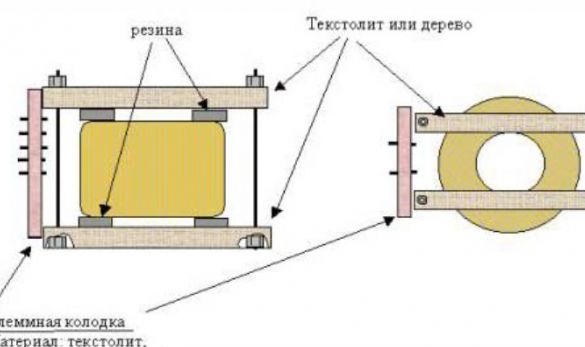
After the case is removed, you need to carefully inspect the magnetic circuit, you need to determine how it is fastened. It happens that the plates are simply laid in the case and fastened with a lock washer. If this is the case, then such a structure can crumble during operation, it is best to pull it with studs or fasten in another accessible way. And sometimes, the design is made in the form of a finished package. If the package of the magnetic circuit is too large, then it can be reduced, since the welding machine will be too heavy. If the engine is large, then it is quite possible that even two electric weldings can be made from it.
As for the grooves of the magnetic circuit, there are several opinions. Some clog the grooves with transformer iron, but our author does not recommend this, as this greatly reduces the efficiency and increases the current consumption. What can be done is to completely cut the grooves with a chisel. The good thing is that the transformer will become lighter. But since the procedure is quite painstaking, most of these grooves do not touch at all.
Step Three Insulation and winding
When the magnetic circuit is already prepared, you will need a keeper tape, with the help of it you need to carefully insulate the casing by wrapping several layers. Particular attention should be paid to the sharp edges in the grooves, since it can easily break through the insulation. To avoid such problems, it is best to first put some kind of dielectric material on the sharp edges, and then wrap the magnetic core with tape.
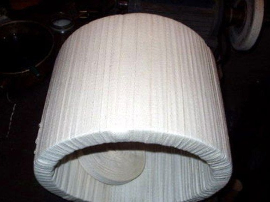
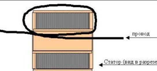
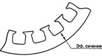
After this, you can proceed to winding the primary winding. Since the diameter of the stator ring is about 150 mm, a rather large wire can be laid in it without worrying that there will not be enough space. Due to the fact that the magnetic circuit has grooves, the cross-sectional area here will gradually change, inside the groove this value is the smallest. The number of turns must be calculated based on this lowest effective value.
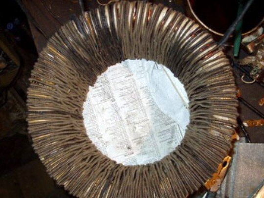
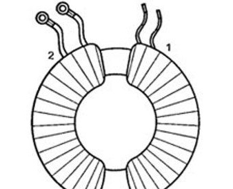
The author winds the primary winding directly along the entire ring of the magnetic circuit. Then the whole thing is again isolated from above with the help of a keeper tape.
Well, the secondary winding is wound on top of the primary. So that the transformer can be adjusted if necessary, the secondary winding must be wound so that it does not overlap the ends of the primary. Then it can be rewound or jacked up if necessary.
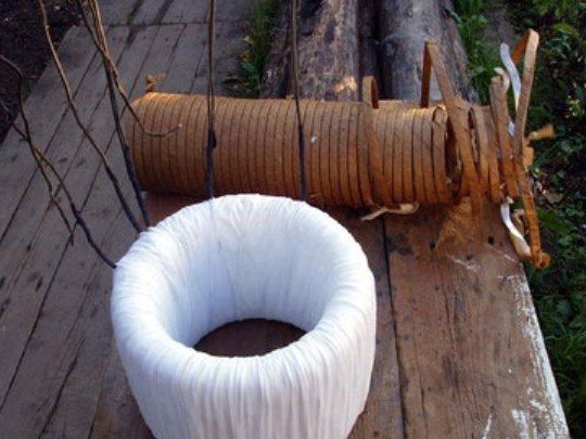

If necessary, the transformer coil can be spread over two shoulders. Then each shoulder can be accessed at any time. But with this design, welding will lose power. As for the technical characteristics of such a homemade product, the welding can cook without problems with an electrode of 4 mm, if it is done correctly, and cut with an electrode of 3 mm. And all this from an ordinary outlet.
This unit consumes during operation up to 10A. With an electrode of 3 mm, you can cook as much as you like, the transformer does not heat up. And if you burn ten pieces by 4 mm, then the transformer will warm up to about 50 degrees.
Winding calculation
For the primary winding, you will need a wire with a diameter of about 2-2.5 mm.The secondary winding is made of a 8x4 mm tire, this applies to copper, for aluminum the cross section should be 15 percent more.
To calculate the number of turns, the formula is used: 48 / (a x c), where (a x c) is the area in square millimeters.
The voltage for the primary winding needs to be selected 210V, since it sits under load. After the value of 180V is reached, every 10V it will be necessary to make bends. They will be needed if welding will need to be used in a place with low voltage.
As for the secondary winding, for a stable arc at idle, it should give out 55-65V.

