

Good day to all! In this article I would like to tell how using Arduino, a set of LEDs and an ultrasonic sensor, you can assemble a device that determines the distance from the observer to the object, in other words, rangefinder. And so let's go!
What do we need:
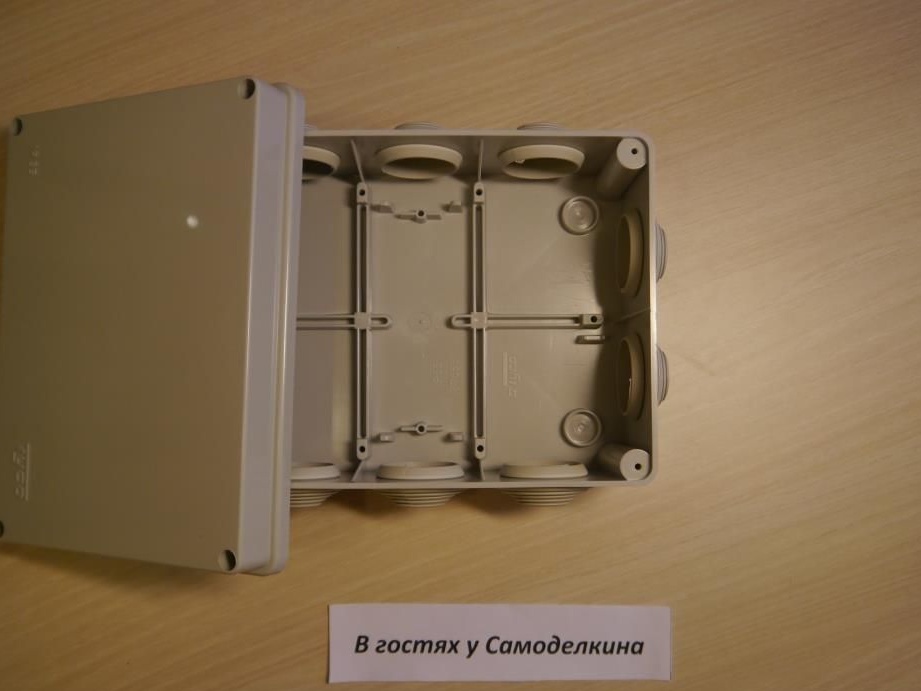
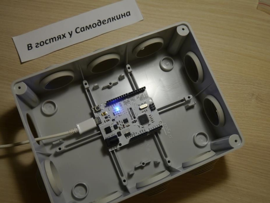
Plain box. It is desirable to be small in size, since it will contain only one microcontroller.
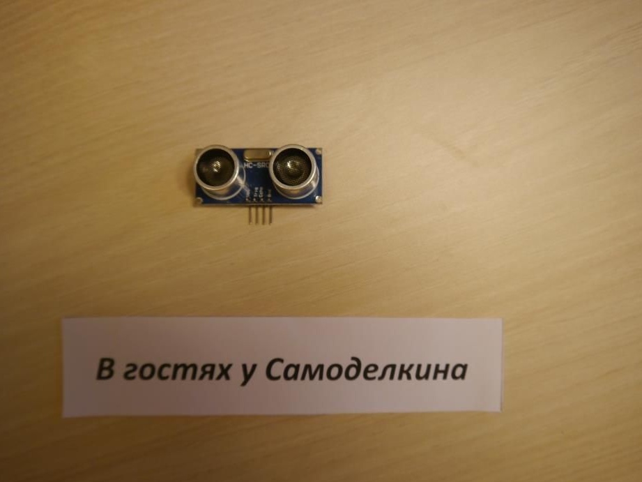
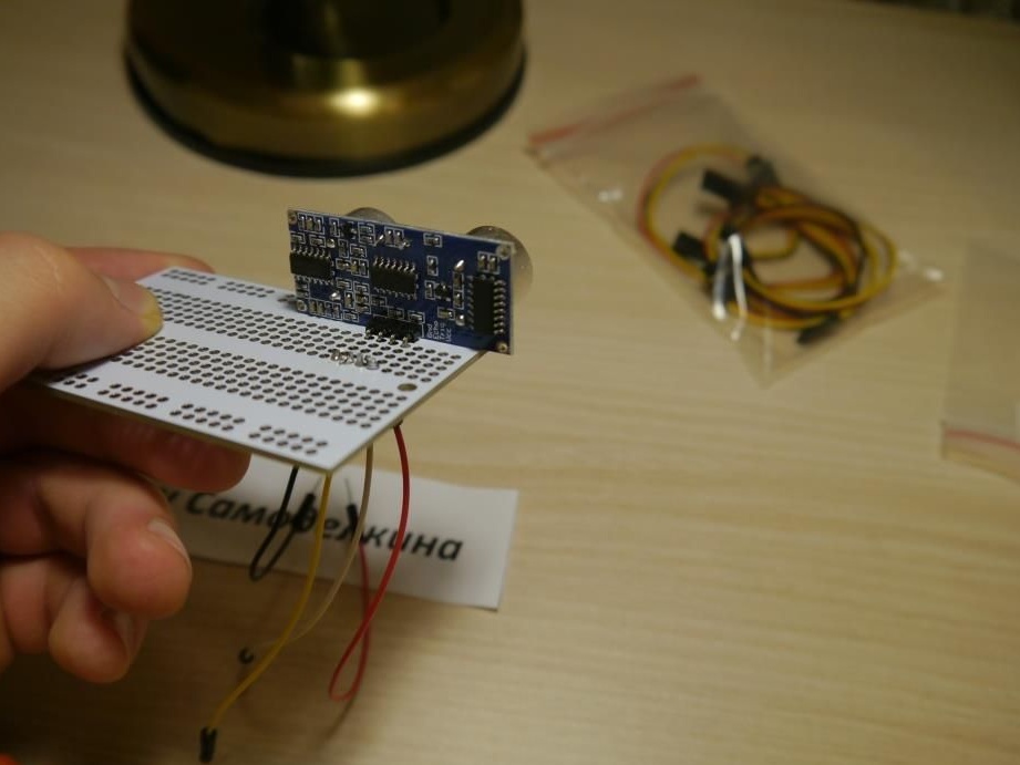
Via ultrasonic transducer HC-SR04 we can determine the distance.
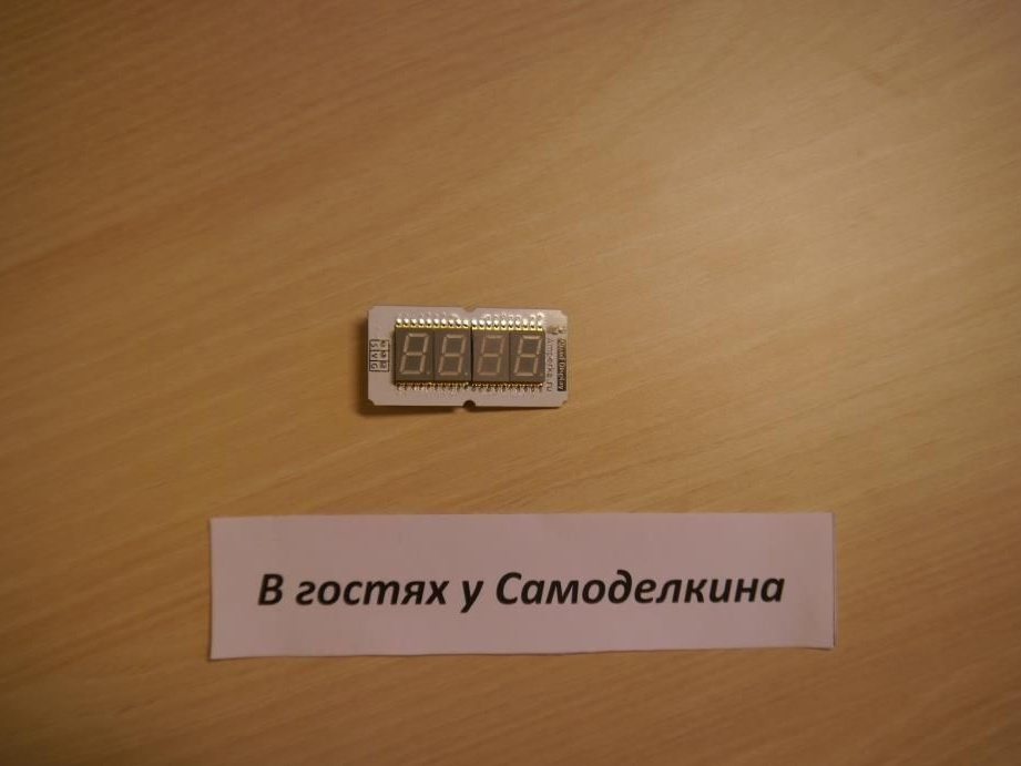
Four digit indicator we need to output the obtained values.
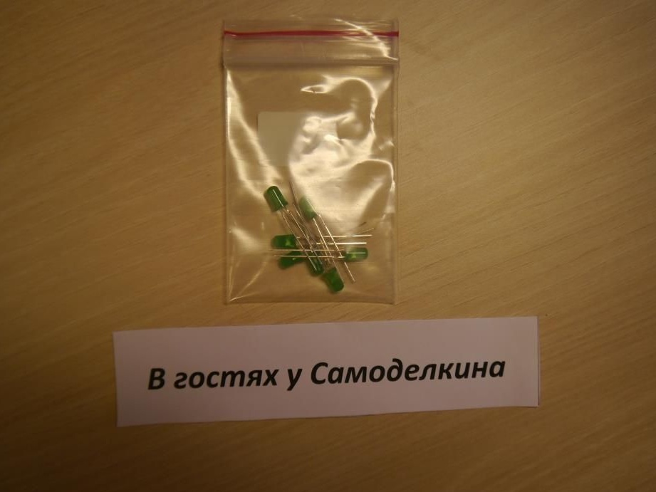
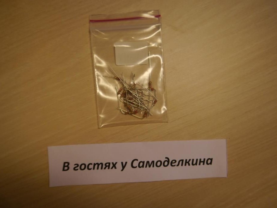
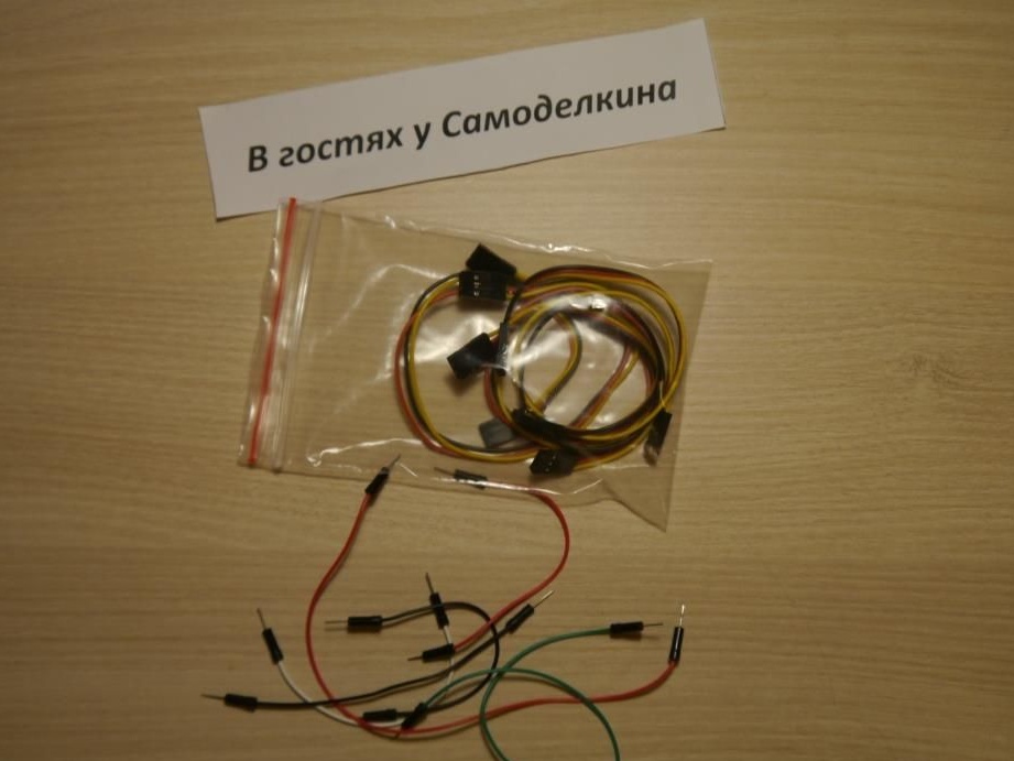
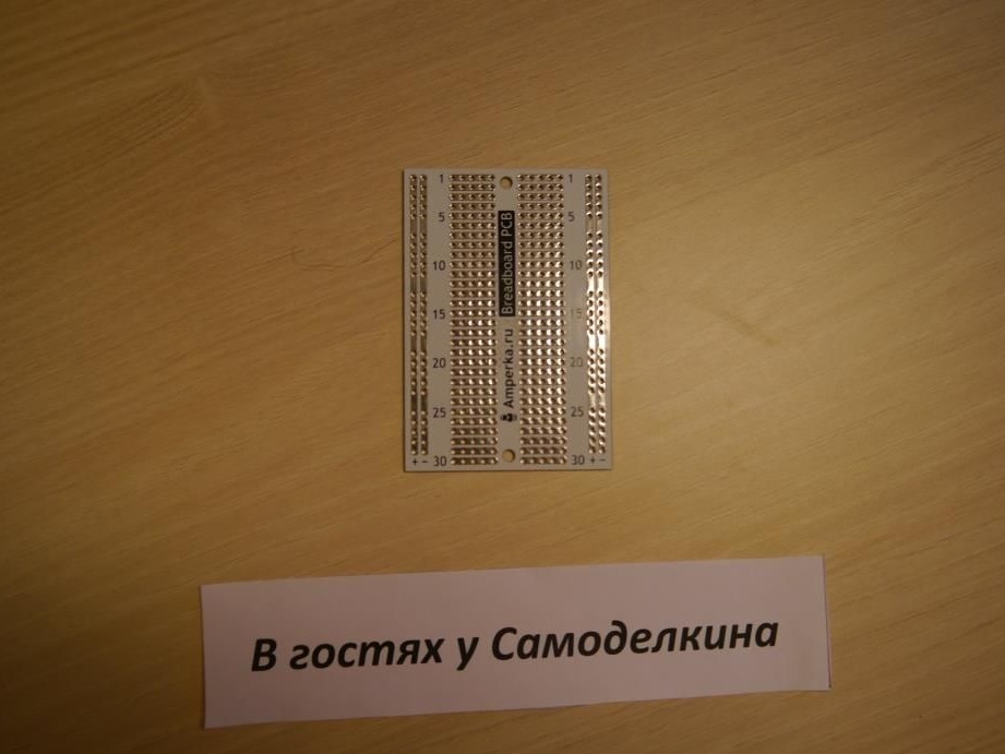
Set LEDs any colors (I used green, as they are brighter), resistors at 220 ohms wires or jumpers as well breadboard.
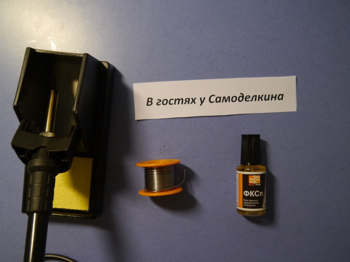
So that the components of our device are securely fastened, I will solder them.
For this we need soldering iron, flux, solder, and breadboard for soldering.
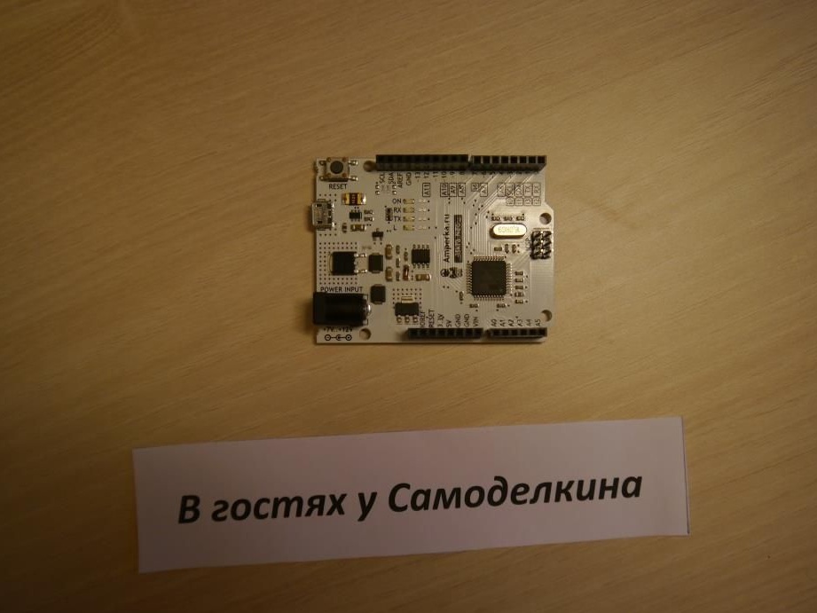
And of course, without Arduino we can not do! (You can choose any microcontroller, I preferred Arduino Leonardo or its equivalent Iskra Neo)
Of the tools we need a soldering iron, as I said above, knife and nippers.

Now let's start assembling the device.
Step # 1
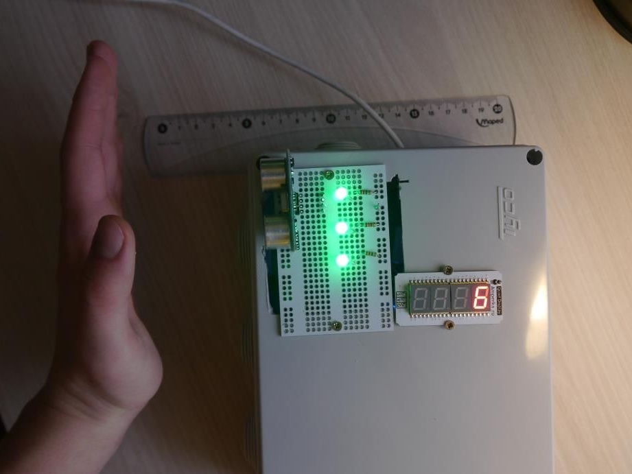
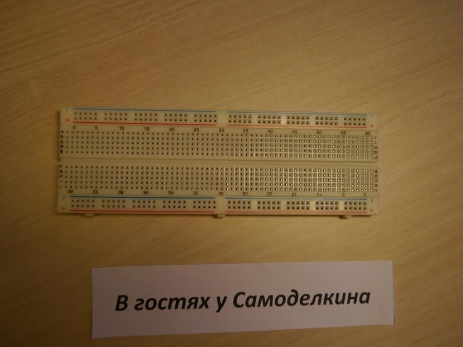
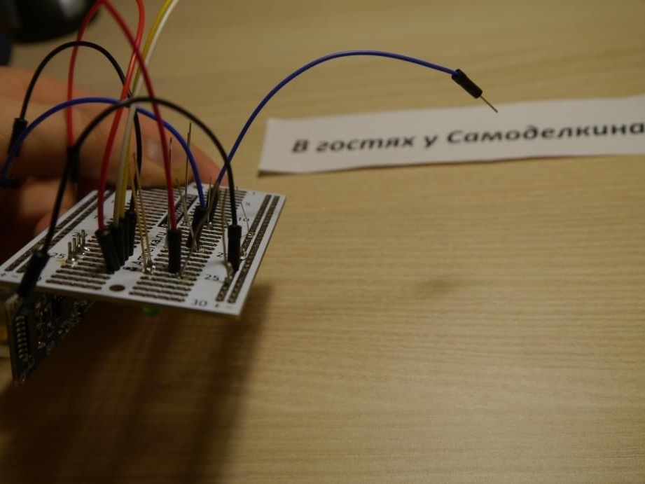
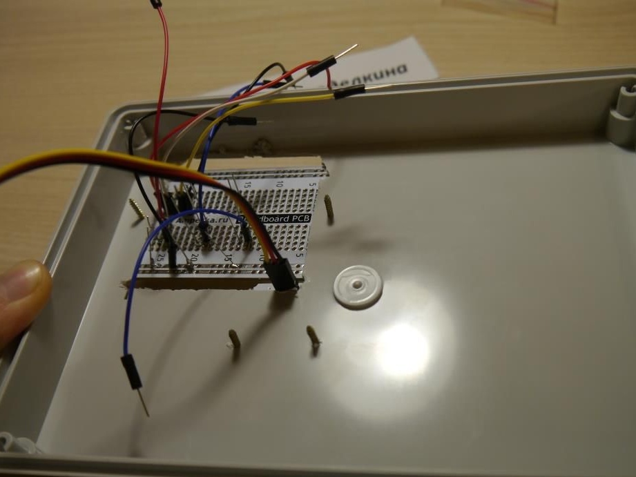
To get started, using a breadboard, we will assemble a prototype of our future device. It will look something like this ..

Do not worry! There is nothing terrible in this mess of wires!
The HC-SR04 sensor has four pins: plus, minus (which we stick into the 5V and GND of the controller), Trig and Echo (we insert the arduino pins into 12 and 11, respectively)
The four-digit indicator has 3 wires: power, ground and signal. The latter is connected to the 9 pin Arduino.
We connect three LEDs to 6, 5 and 4 contacts of the controller in series with resistors. Do not forget about the polarity. Current flows from a longer leg to a shorter one.
That's all, when we assembled our device on a breadboard, uploaded the sketch (it will be at the end of the article) and made sure that everything works, feel free to start soldering.
Step number 2
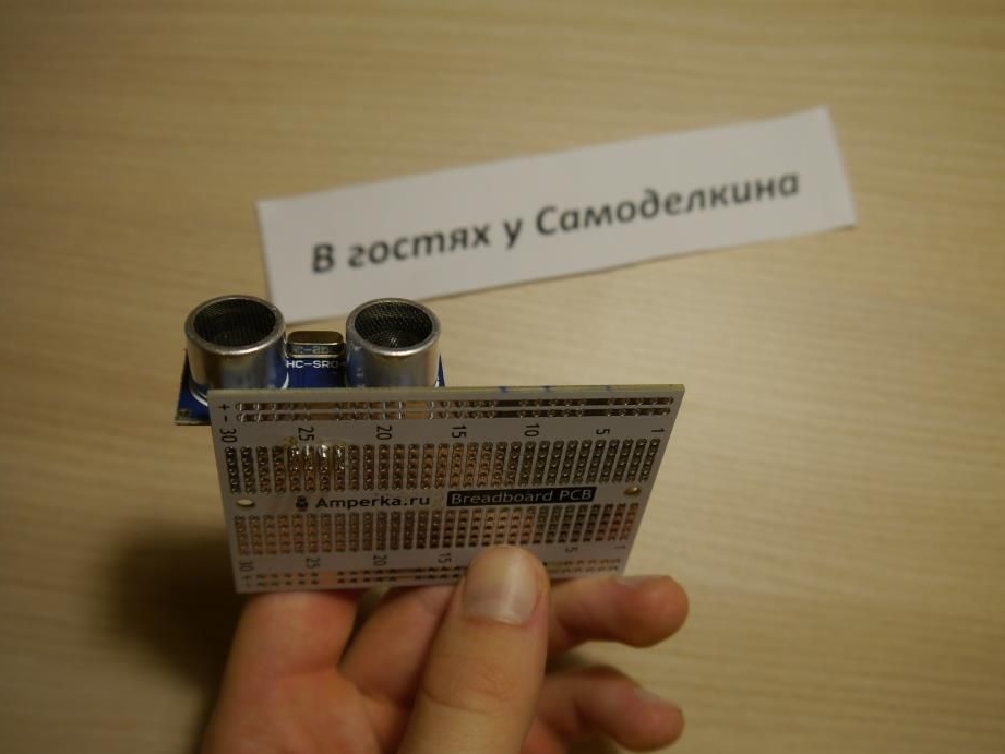
First, solder the ultrasonic sensor to the breadboard. I used a small breadboard in size, as the number of elements does not exceed 7.
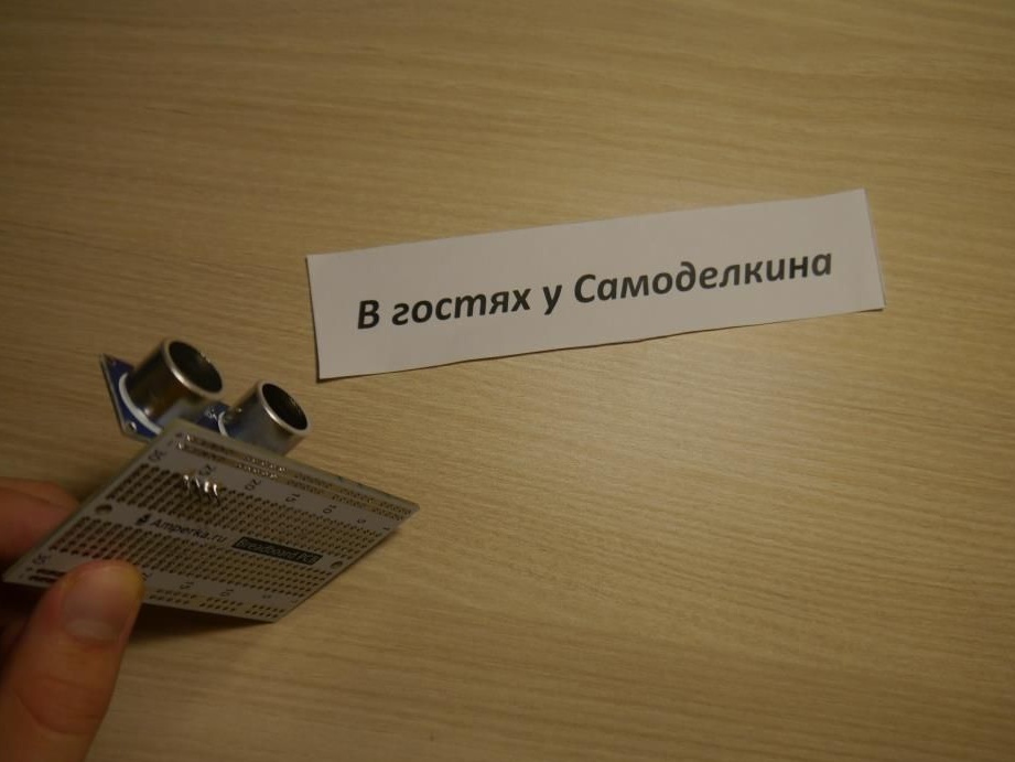
After that, with the help of nippers, bite off the legs (I apologize for the tautology), making them shorter so that they do not interfere and look prettier!
After that, solder the four wires against the sensor contacts.
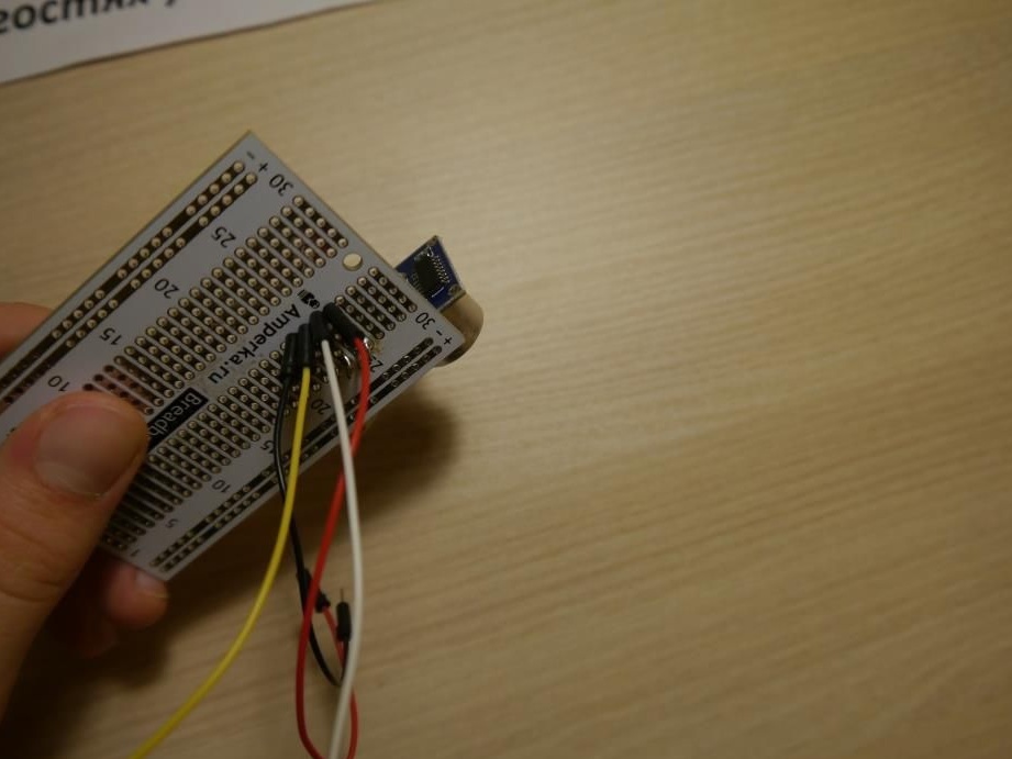
Also do not forget about the nippers!

Step # 3
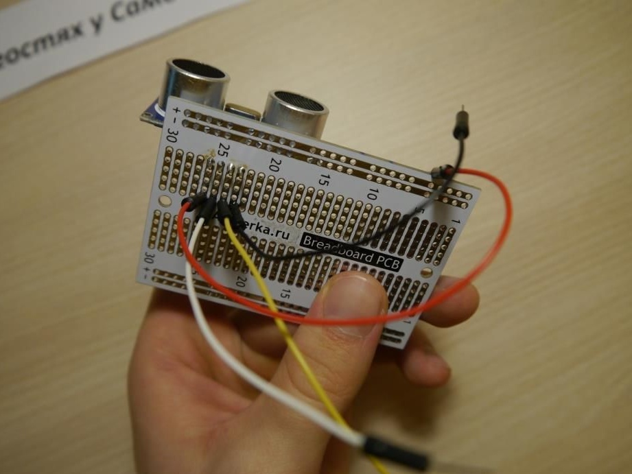
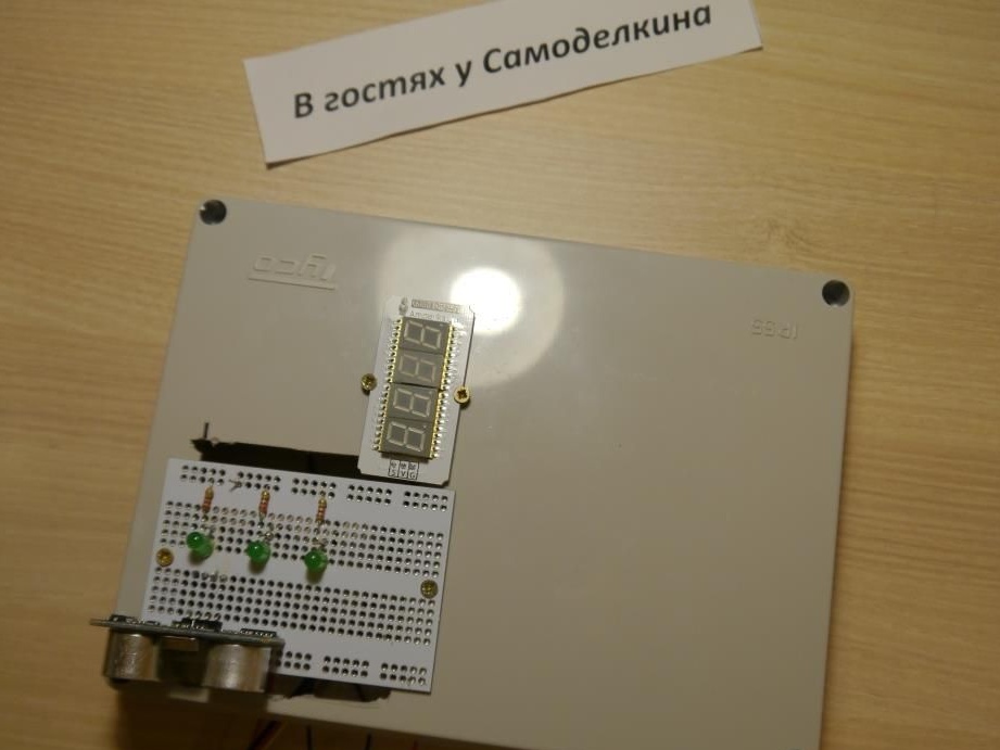
The sensor is in place, it remains to solder the three LEDs together with the resistors.
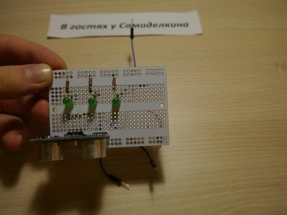
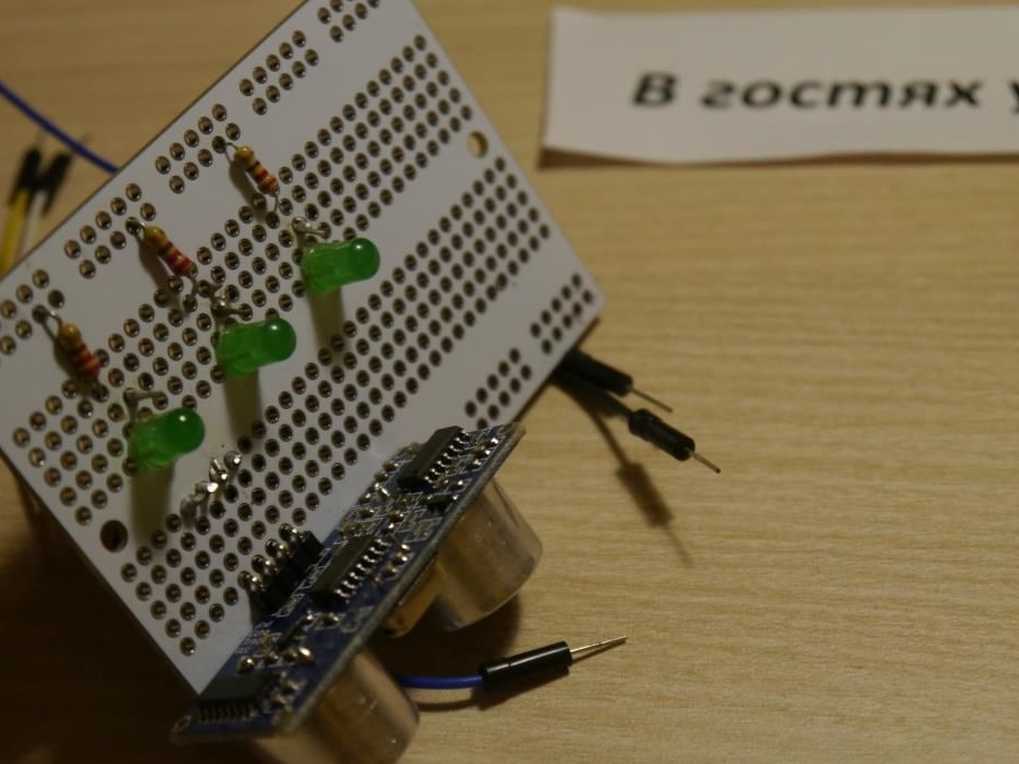
On the reverse side, it looks like this:
Step # 4
On the side of the box, cut a round hole for food.
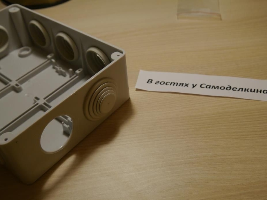
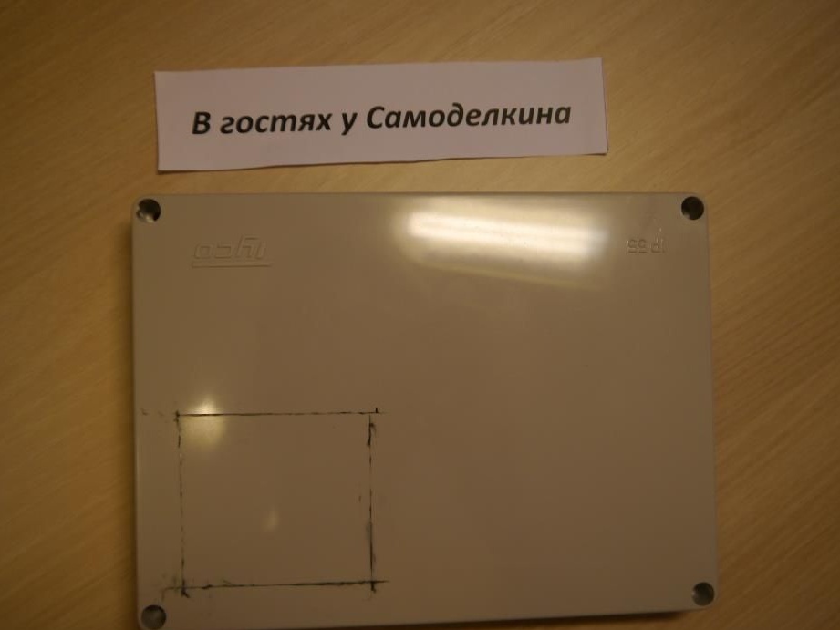
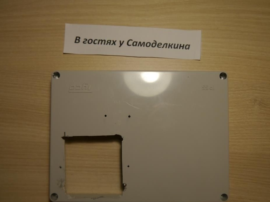
On the lid, you need to cut a cavity to the size (slightly smaller in length) of your breadboard, and also drill holes for screws.
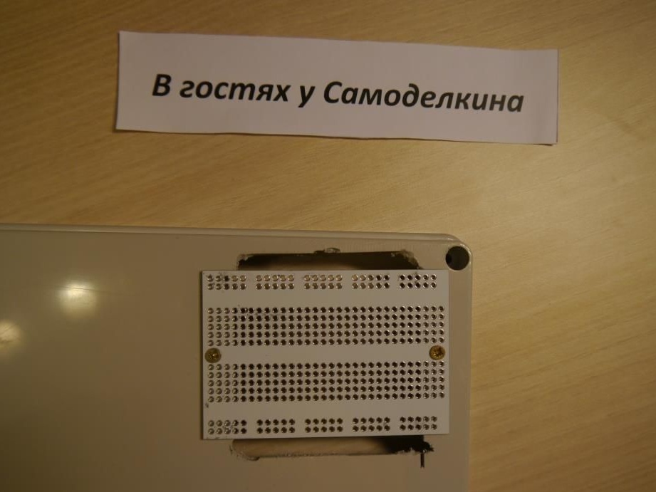
Now, if we screw an empty breadboard without elements on it (I did it just for demonstration ..), we get something like the following:
Step # 5
So, to make it more convenient, I propose to first connect the wires to the arduino, and only then screw the breadboard to the box lid. Also, do not forget about our indicator, which I placed above the layout.

Everything on this device assembly is finished!
It remains only to download the next sketch and enjoy the toy!
#include
#include
NewPing sonar (12.11, 400);
int a, j, b;
unsigned long t = 0;
int masiv [] = {1,0,0,0,1,0,0,0,1};
void setup ()
{
 for (int i = 4; i & lt; 7; i ++)
 {
   pinMode (i, OUTPUT);
 }
 displayClear (9);
 for (int i = 4; i & lt; 7; i ++)
 {
   digitalWrite (i, 0);
 }
  }
void loop ()
{
  j = 7;
  for (int i = 0; i100) tone (2,70);
    digitalWrite (j, masiv [i]);
    while (millis () & lt; = t + b)
    {
    delay (50);
    a = sonar.ping_cm ();
    displayInt (9, a);
    b = a;
    }
    t = millis ();
    if (j == 4) j = 7;
    if (i == 8)
    {
     digitalWrite (4.1);
     while (millis () & lt; = (t + b) + (b * 2))
     {
    delay (50);
    a = sonar.ping_cm ();
    displayInt (9, a);
    b = a;
     }
     digitalWrite (4.0);
     t = millis ();
    }
  }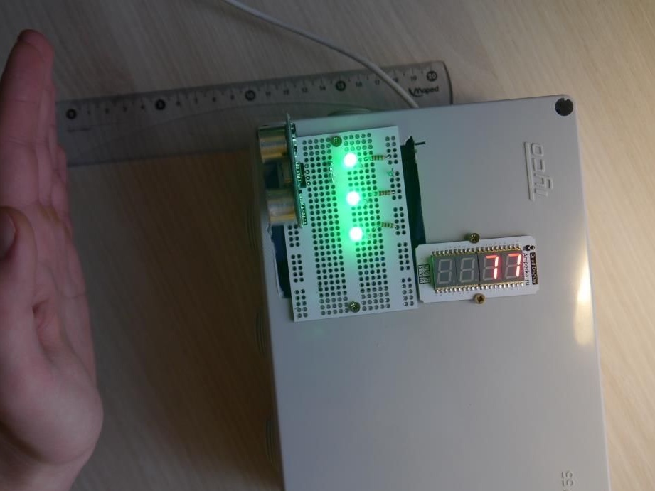
A few words program code. Thanks to him, our three LEDs will flash alternately one after another, and the speed of their blinking will depend on the distance to the object, which is calculated by the ultrasonic sensor. But in order to make the LEDs blink, it is not entirely logical to use the delay () function, since when it is used, the controller freezes and no calculations are performed. There are several ways to solve this problem. In particular, one of them is the use of the millis () function, which returns a number in milliseconds from the moment the controller works. And how do we delay a conditional 100 milliseconds? To do this, I created an essentially empty cycle, the exit from which will be only after these 100 milliseconds, and then the program proceeds to turn on / off the LEDs.
Well that's all! Thank you for reading this article to the end. I hope you not only liked her, but also inspired a new sea crafts and inventions!