» Electronics » Arduino »Universal tracked chassis for the robot

Universal Tracked Chassis for Robot


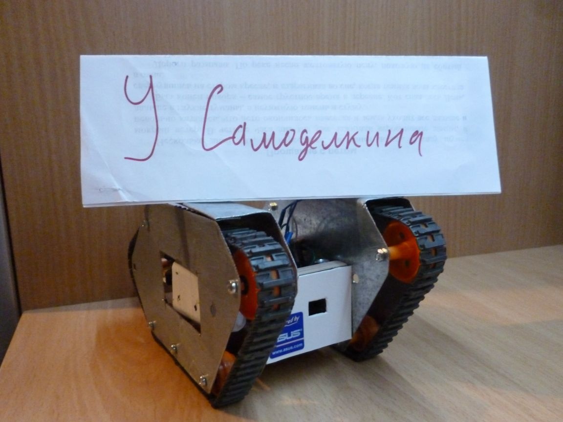
In my free time I practice all kinds of Arduino projects. Quite often for the implementation of a project requires robot - A platform that meets a number of requirements: free movement, the ability to install additional equipment and expand capabilities, as well as moderate cost. Here is such a robot platform or, simply, a caterpillar chassis I will do. Of course, I am posting the instruction to you for trial.

We will need:

- Tamiya 70168 dual gearbox (can be changed to 70097)
- Tamiya 70100 set of rollers and tracks
- Tamiya 70157 platform for attaching the gearbox (can be replaced with a piece of plywood 4 mm)
- Small pieces of galvanized sheet
- Plywood 10 mm (a small piece)
- Arduino Nano
- DRV 8833
- LM 317 (voltage stabilizer)
- 2 LEDs (red and green)
- Resistors 240 Ohms, 2x 150 Ohms, 1.1 kOhms
- Capacitor 10v 1000uF
- 2 single row combs PLS-40
- 2 PBS-20 connectors
- Inductor 68mkGn
- 6 NI-Mn 1.2v 1000mA batteries
- Connector dad-mom two pin to wire
- Wires of different colors
- solder
- Rosin
- soldering iron
- Bolts 3x40, 3x20, nuts and washers for them
- Bolts 5x20, nuts and reinforced nuts to them
- drill
- Drills for metal 3 mm and 6 mm

Step 1 cut the metal.
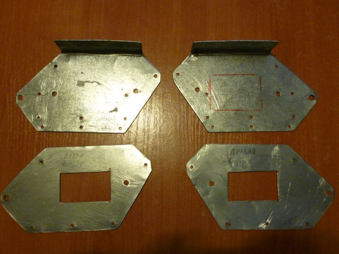
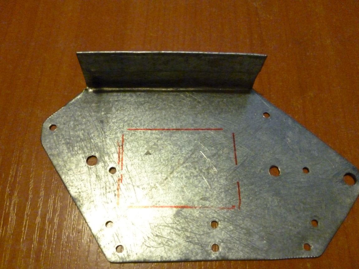
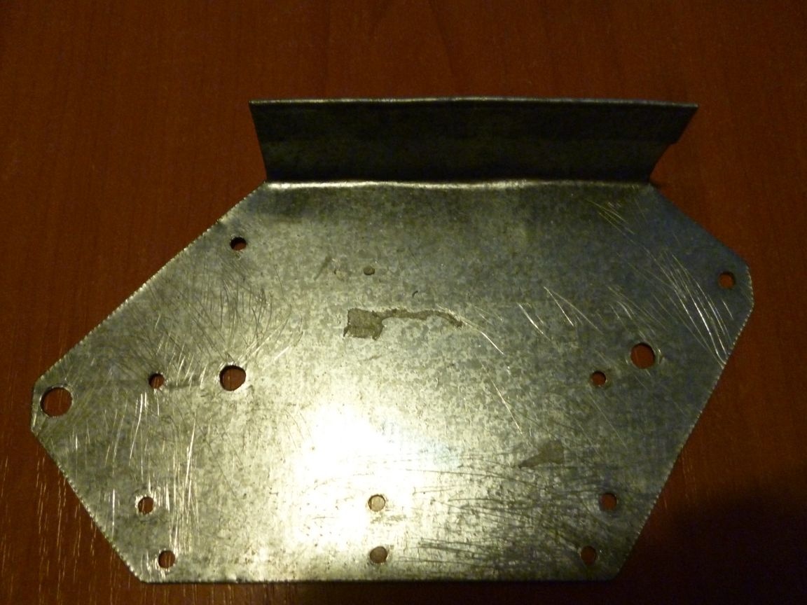
First, we need to cut from sheet metal (preferably galvanized) to cut four parts. Two parts per track. For this scan, we cut out two details:


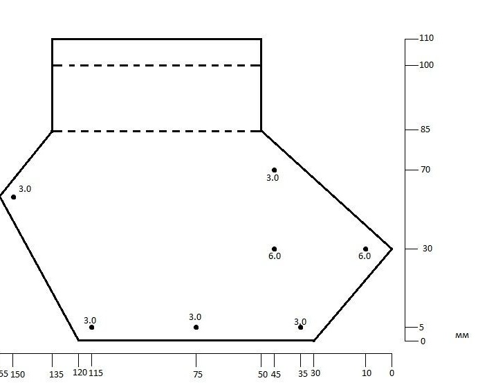
The dots indicate the places where it is necessary to drill holes, the diameter of the hole is indicated nearby. 3 mm holes are needed for hanging with a roller, 6 mm for passing wires through them. After cutting and drilling, you need to file through all the edges without leaving sharp corners. Bend along the dashed lines 90 degrees. Be careful! We bend the first part in any direction, and the second bend in the opposite direction. They must be symmetrically bent. There is one more nuance: it is necessary to drill holes for self-tapping screws that fasten our plates to the base. Do this when the base is ready. We put the blank on the base and mark the drilling places so that the screws fall into the center of the chipboard. We do two more details on the second scan:


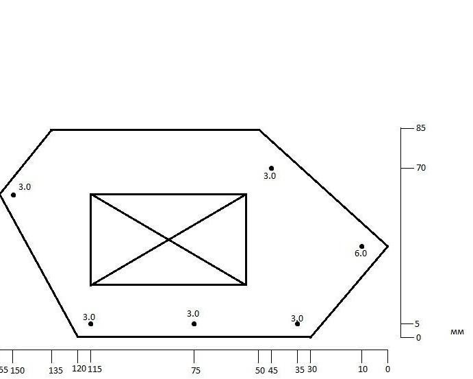
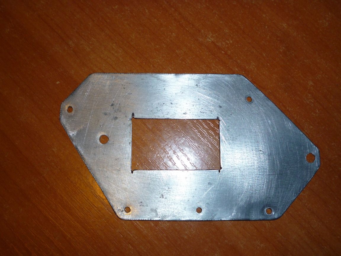
The inner rectangle must be cut. Next, we do the same thing, cut, drill, clean. And in the end we get the blanks:


Step 2 prepare the basis.
We assemble the gearbox according to the attached instructions. We fasten it to the site. If there is no platform, we cut a 53x80 mm rectangle from plywood 4 mm and fasten the gearbox to it. Take 10 mm plywood.Cut two rectangles 90x53 mm and 40x53 mm. Inside the small rectangle, we cut out another rectangle, so that we get a frame with a wall thickness of 8 mm.


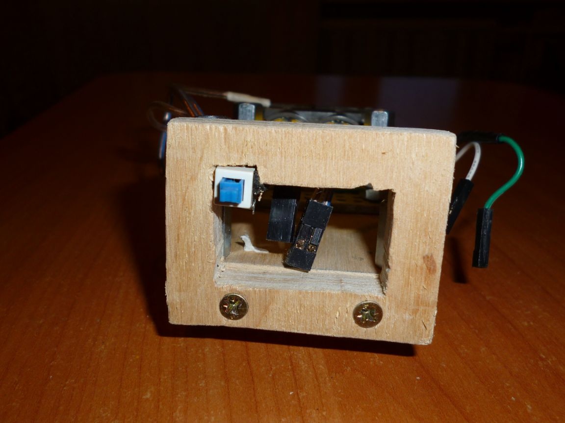
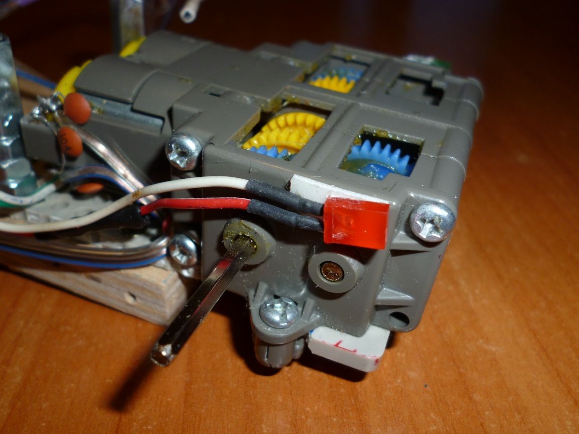
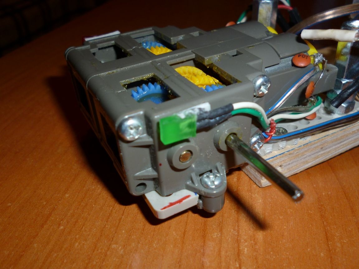
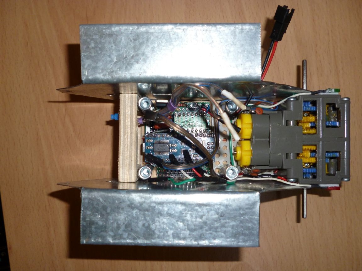
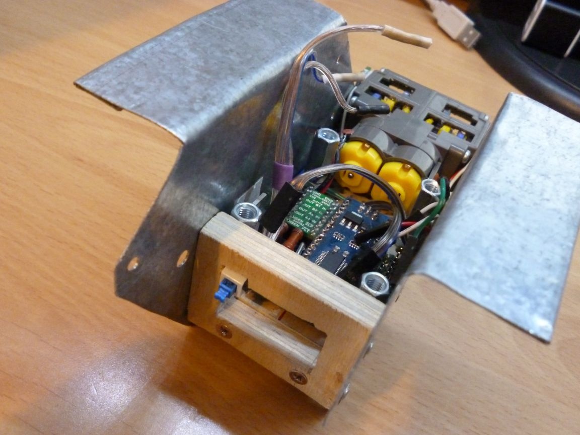
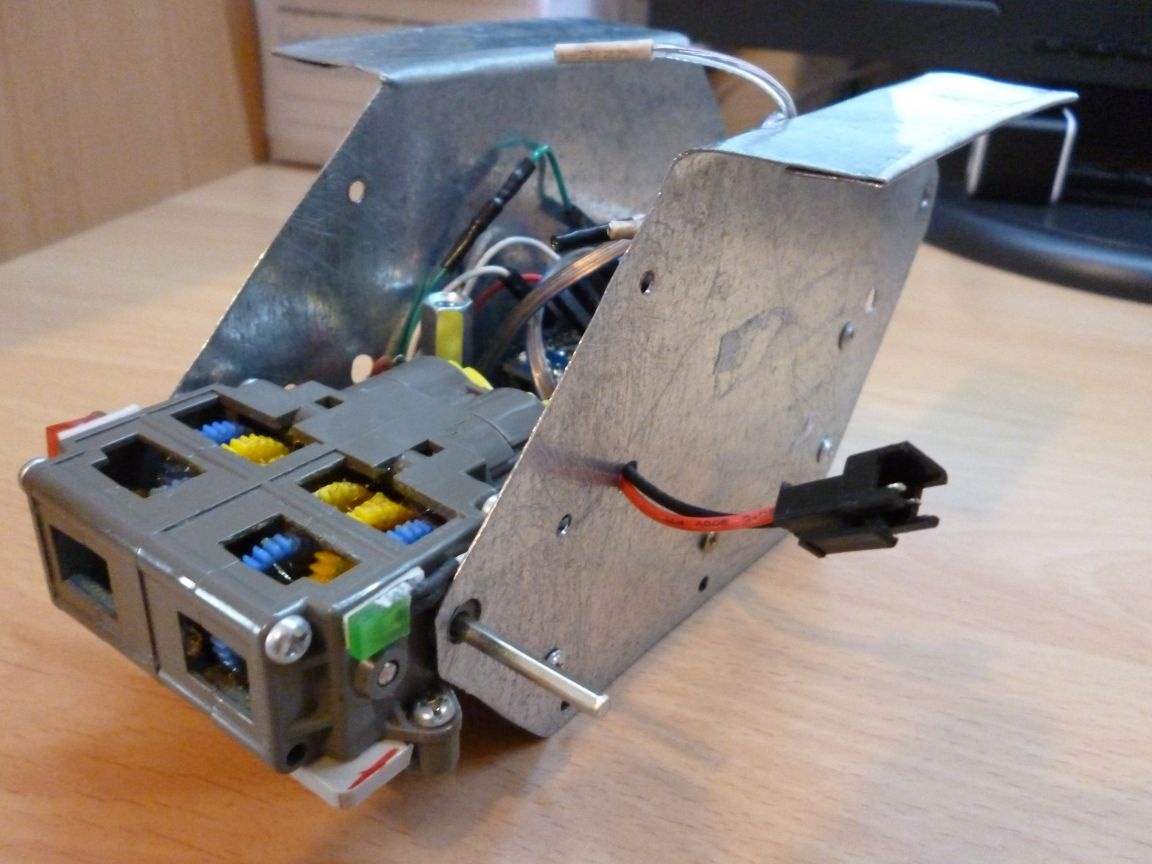
Twist everything as shown in the photo:


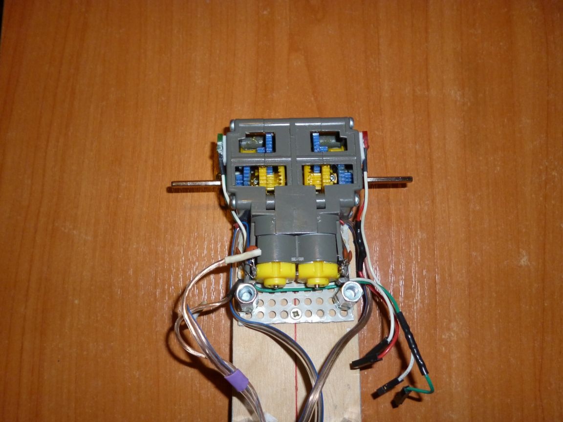
In the corners of the platform, drill holes of 6 mm and insert our 5x20 bolts into them; from above we wind reinforced nuts. They are needed for subsequent mounting of various mechanisms or boards. For convenience, we immediately glue the LEDs:


Step 3 is an electrician.
For control we will use Arduino Nano. DVR 883 engine driver. On the circuit board, we assemble everything according to the scheme.


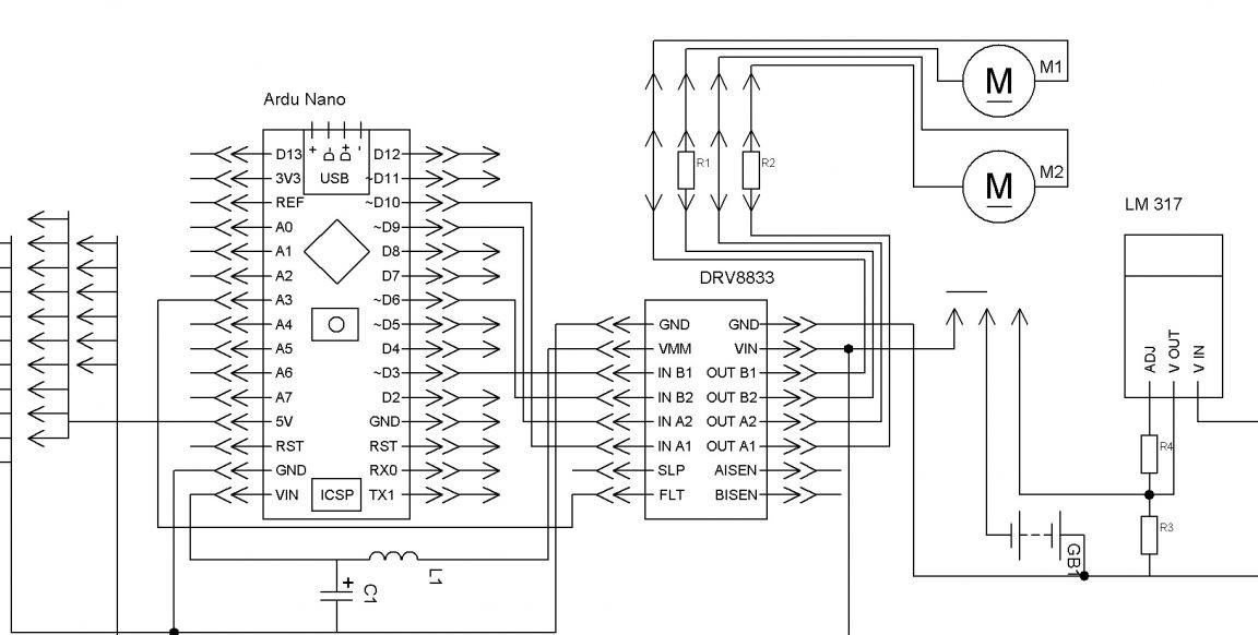
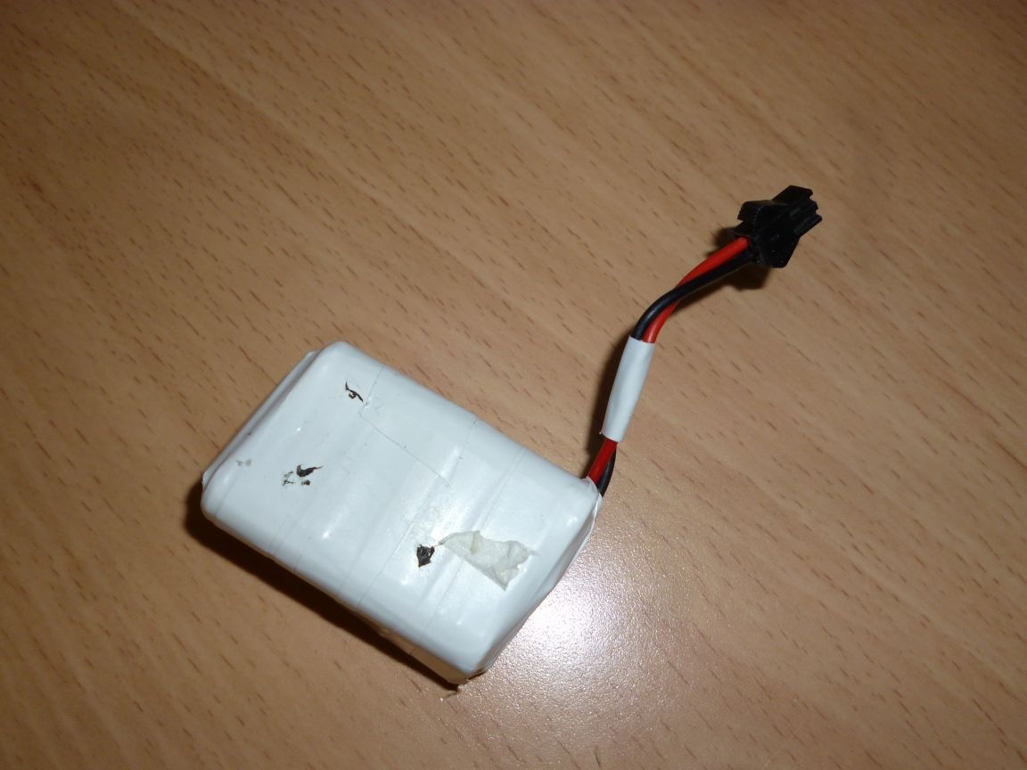
L1 is an inductor and C1 is needed to stabilize the Arduino voltage. Resistors R1 and R2 in front of the motors are current-limiting, their rating must be selected for specific motors. They work fine for me at 3 ohms. LM317 is needed to charge the batteries. The input can be supplied with voltage from 9.5 V to 25 V. R3 - 1.1 kOhm R4 - 240 Ohm. The “pins” on the left are used for subsequent connection of various devices (Bluetooth, 433 MHz communication module, IR, Servo, etc.). For power we will use 6 Ni-Mn 1.2v 1000mA batteries soldered in series and wound with electrical tape.


Step 4 we collect the basis.
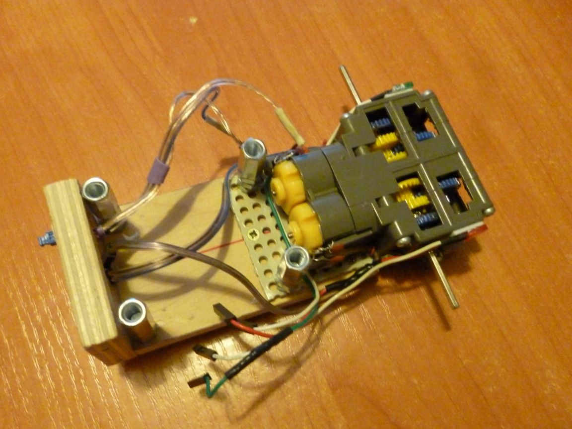
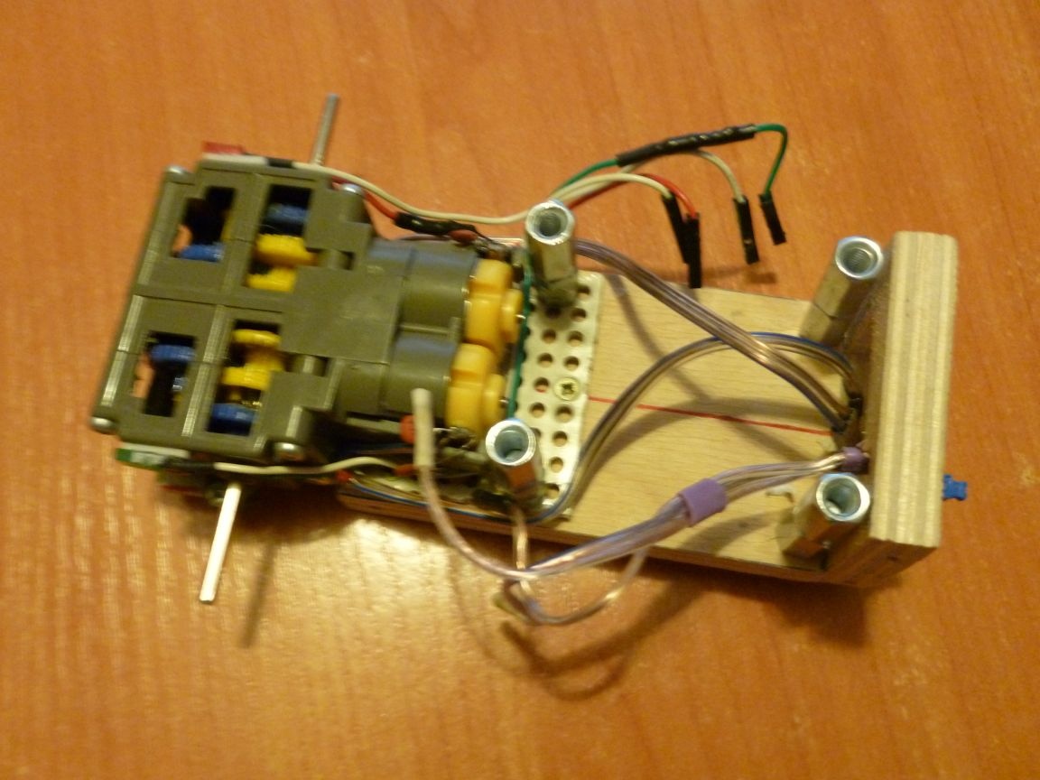
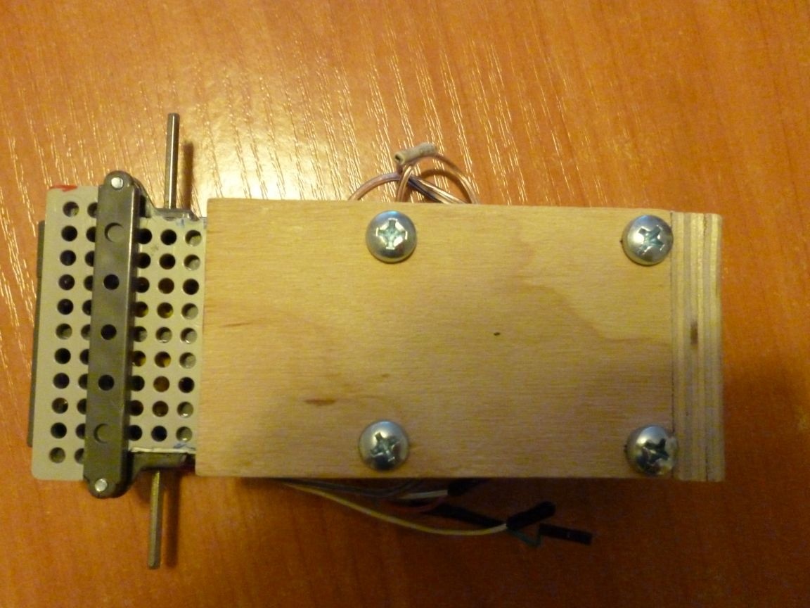
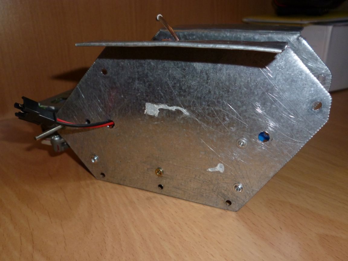
We take our base, on a double-sided tape we glue a board on it. The metal parts for the first scan need to be screwed onto small self-tapping screws to the base on the sides, bent outward. Be careful to screw it so that the extreme 6 mm hole is put on the output axis of the gearbox, the bottom of the part must be parallel to the base and symmetrical in relation to the second such part. The result should be:


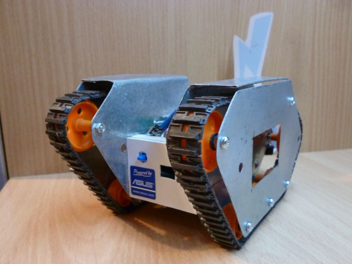
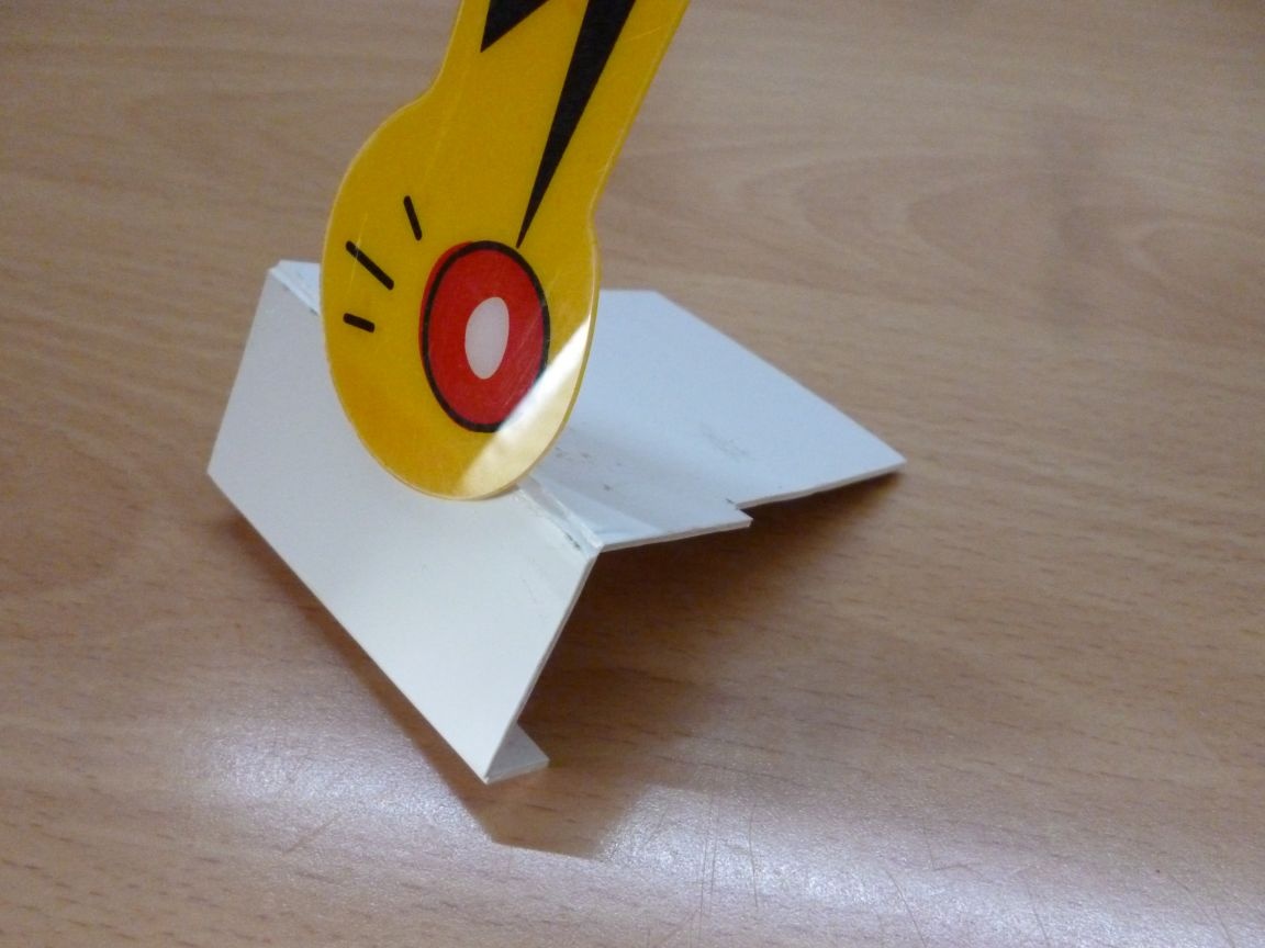
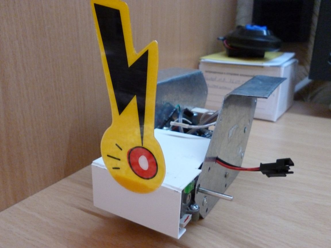
To give our homemade aesthetic look, add a couple of details. It's not obligatory. From white plastic, cut out a 110x55 mm rectangle and bend as shown in the photo. The tail is also optional, but I liked how it looks and shakes when moving:


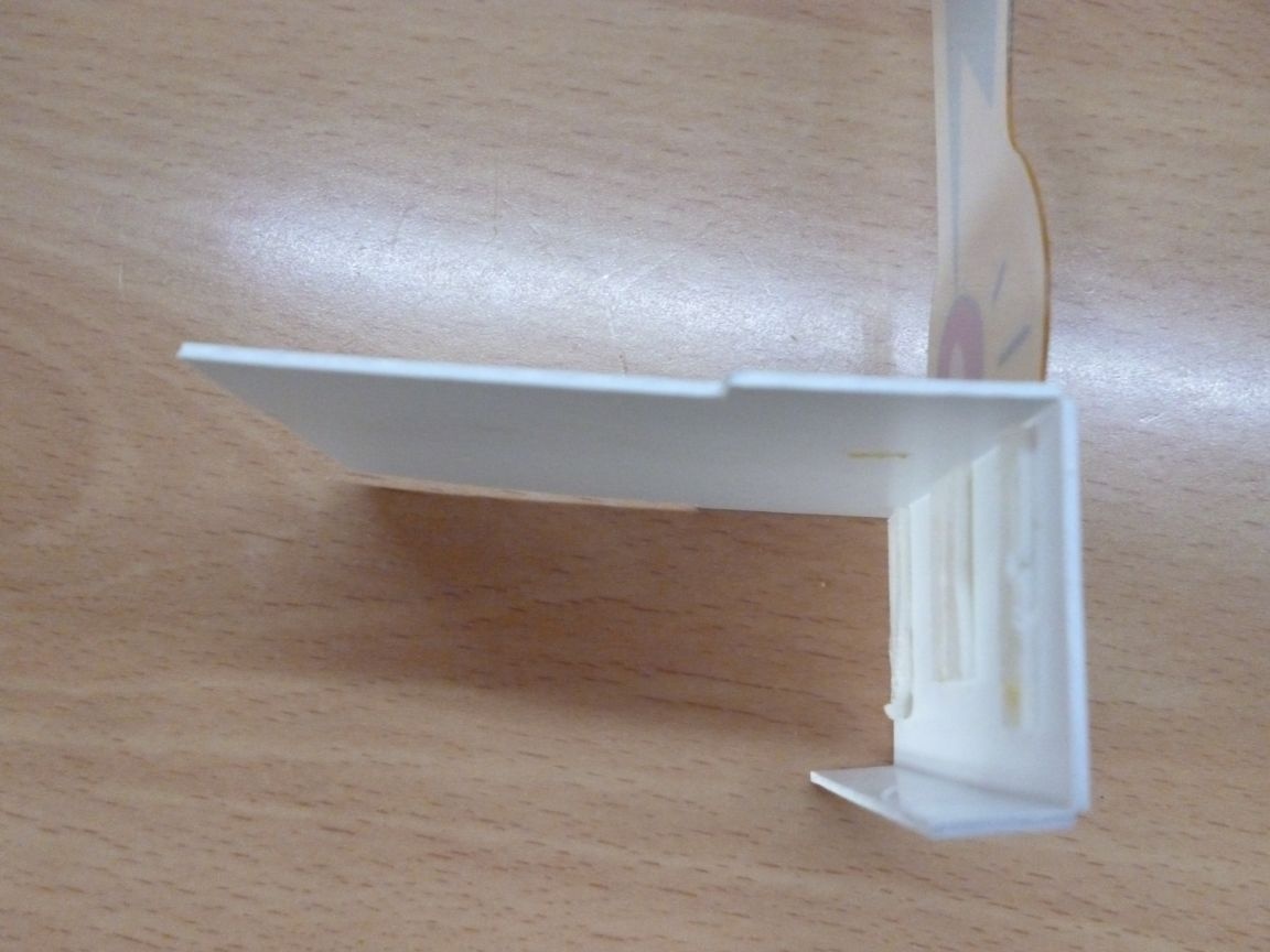
This cover covers the gearbox so that dirt does not get into it, and it makes so less noise. Next, we also cut a 52x41 mm rectangle from white plastic. We make holes for connecting the Arduino and the power button as in the photo:


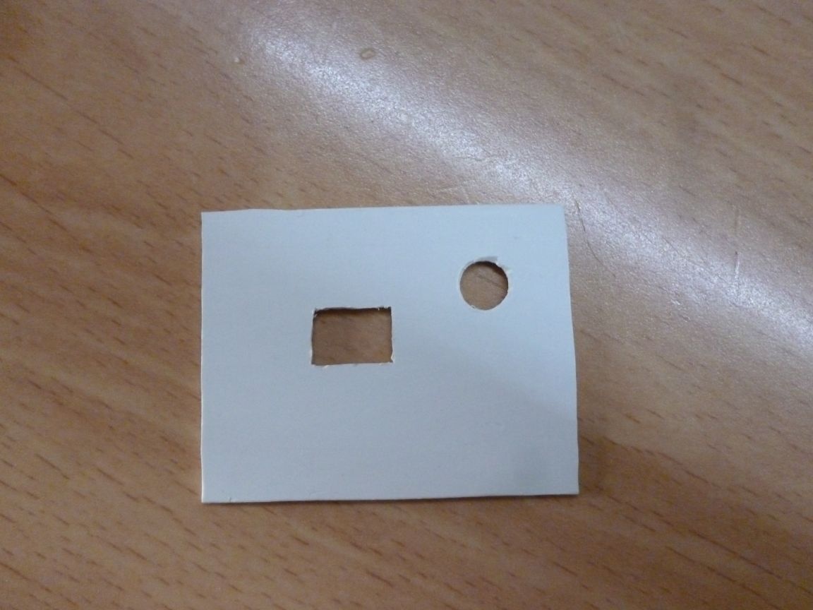
Glue it all on a double-sided tape:
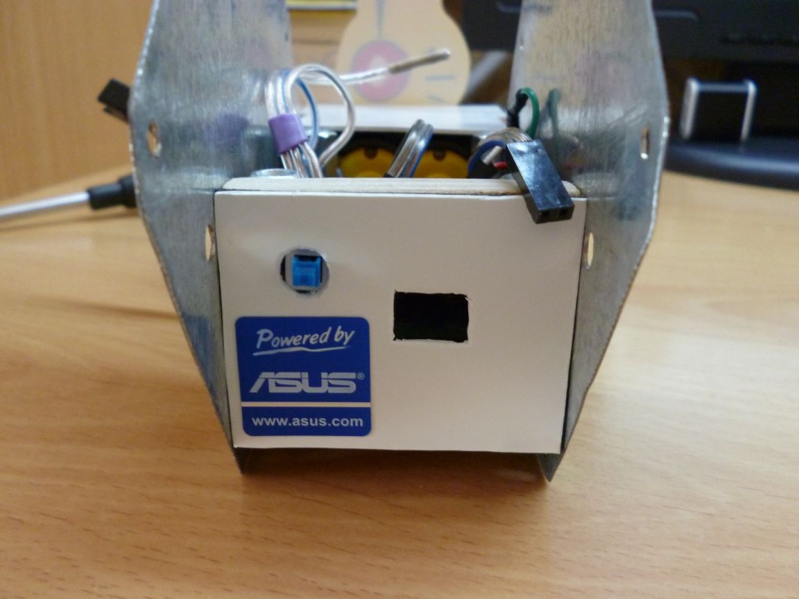

Sticker for beauty.


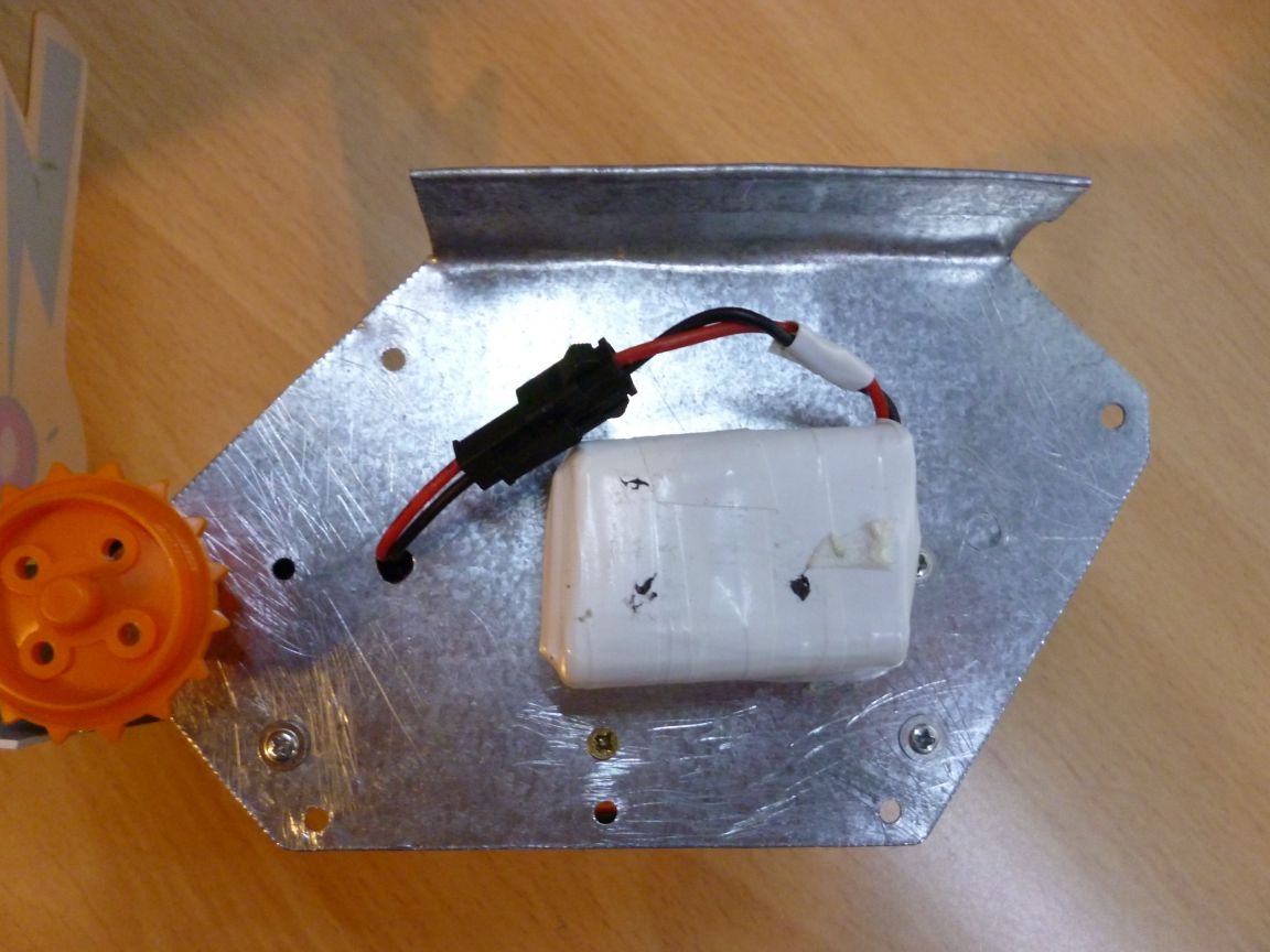
These two parts can be made from almost any material that is at hand. It can be thick cardboard (which can then be painted), fiberboard, thin plywood or a piece of plastic of any color. Do not forget about the batteries. Glue them on a double-sided tape on the right metal part of the base:


Step 5 Caterpillars.
Here we will need our second scan blanks. We insert bolts with a 3x20 semi-cylindrical head into the 3 mm hole. Put on the washers and tighten the nuts:


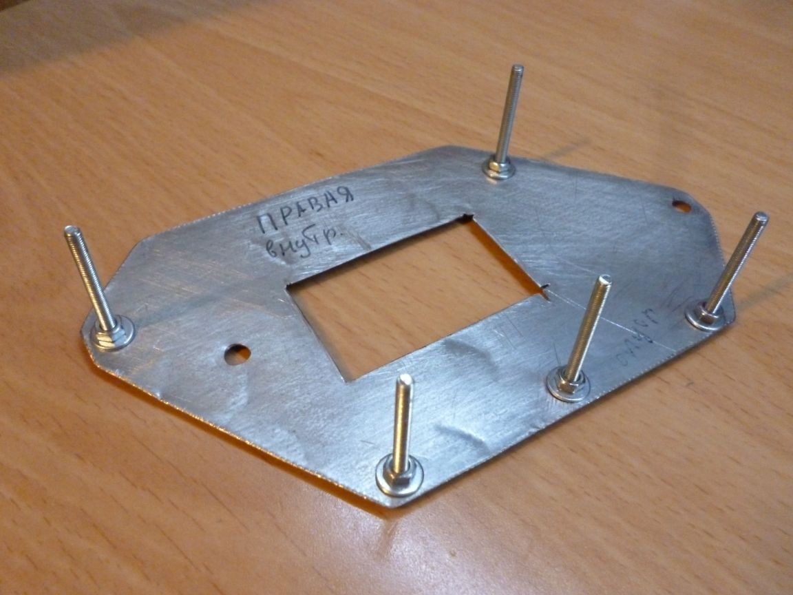
Washers must be worn before the rollers. I was not too lazy and ordered plastic washers. You can use ordinary metal, but then our tracks are very noisy. After the rollers, we tighten the nuts without tightening, so that the rollers rotate freely.


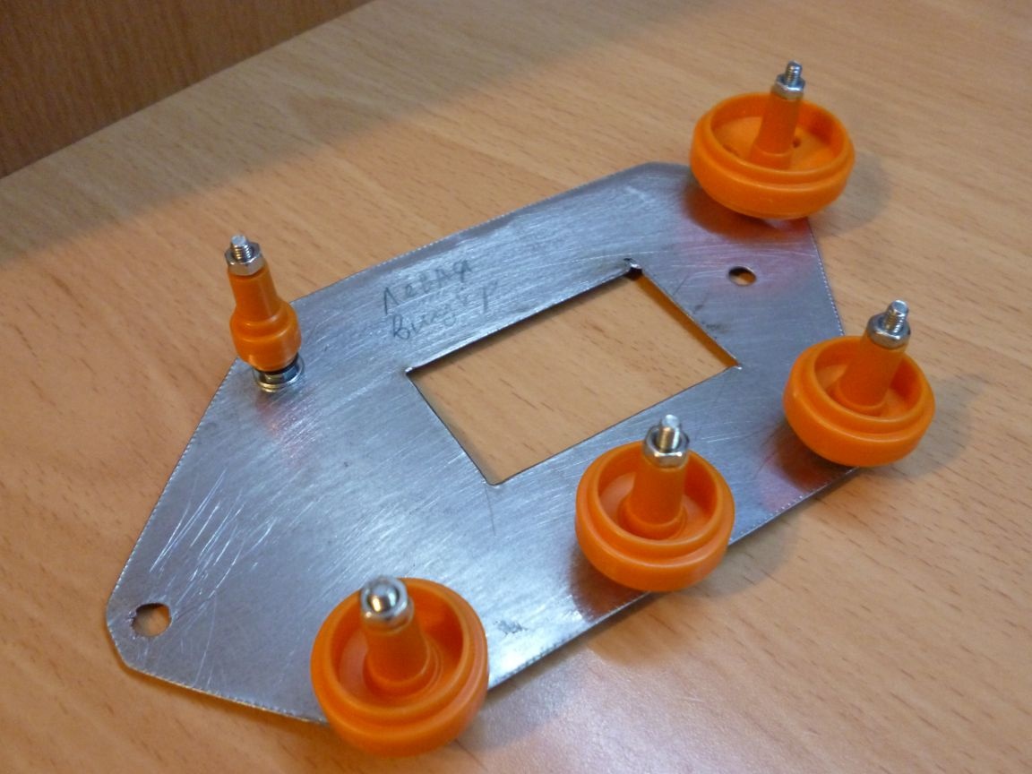
We put rubber tracks on the rollers. We put the plate along with the rollers on the base, making sure that the bolts fall into the holes. And tighten the nuts. We get an almost finished tracked chassis:
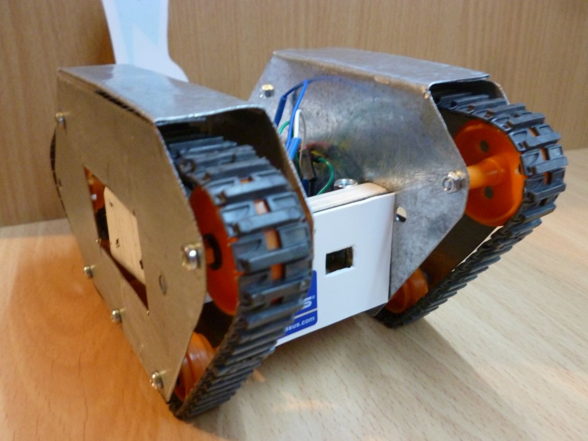

Step 6 firmware.
unitank.rar [5.3 Kb] (downloads: 127)

In my opinion, it is most convenient to write firmware in the Arduino IDE. The chassis we assembled is universal and firmware is required depending on the specific purpose. You can connect a Bluetooth module and use your phone or computer to control. It is also possible to connect an IR sensor and use an IR remote control. Another control option is the use of a 433 MHz module to communicate with the remote control. Based on the chassis, it is possible to make a robot following the line or any other autonomous one. I post firmware for Bluetooth, 433 MHz and IR.
Convenience
Total Voters: 71
9.4
9.2
8.6

Add a comment

    • smilesmilesxaxaokdontknowyahoonea
      bossscratchfoolyesyes-yesaggressivesecret
      sorrydancedance2dance3pardonhelpdrinks
      stopfriendsgoodgoodgoodwhistleswoontongue
      smokeclappingcraydeclarederisivedon-t_mentiondownload
      heatirefullaugh1mdameetingmoskingnegative
      not_ipopcornpunishreadscarescaressearch
      tauntthank_youthisto_clueumnikacuteagree
      badbeeeblack_eyeblum3blushboastboredom
      censoredpleasantrysecret2threatenvictoryyusun_bespectacled
      shokrespektlolprevedwelcomekrutoyya_za
      ya_dobryihelperne_huliganne_othodifludbanclose
27 comments
Quote: maxim0512
LM317 is needed since my 12 volt power supply
Yes, even at 100, if the current is limited, then Uxx (within reasonable limits) does not play a role.
Quote: maxim0512
Current set at 150 mA
But because of this, the voltage stabilizer is really useful: since there is a fast (current greater than 0.1C) charging, in order not to damage the batteries, it is necessary to stop charging, avoiding overcharging and, as a result, overheating.
Quote: maxim0512
you get to the bottom of an element that is not so important.

I didn’t get to the bottom, but indicated errors. Feel the difference.
Author
Ivan_Pokhmelev,
I also wanted to add, you got to the bottom of an element that is not so important. The power supply of the chassis can be arranged in different ways and does not matter. You can use lithium batteries and then the charging is completely different. You can just take the battery box and insert 5 AAA batteries. Or just an external power supply. You can remove this element in the diagram and the essence itself will not change.
Author
Ivan_Pokhmelev,
Yes, the chassis is battery powered. An external power source is only needed to charge the batteries. In this article, I did not describe the charge process in detail, since I have a home-made power supply unit and its manufacture is a separate issue. Only what is on the chassis board is described here. In general, batteries can be charged by disconnecting them from the chassis and connecting to the charger, but again, battery charging and charger are a separate issue.
The current is set to 150 mA (by connecting an ammeter and adjusting the power supply).
LM317 is needed because my power supply unit is 12 volts (and there is also a 9 volt which I also charge sometimes).
And what is the current limiting of this power supply? And if there is a current limitation to LM317, then why a voltage stabilizer? After all, you wrote:
Charging by closing 2 and 3 contacts. Operating mode 1 - 2.
, that is, the work is done not from an external source, but from the battery.
Author
I have a current limit on the power supply up to Lm317.
That is, it is not interesting to search for yourself? To understand on your own, read literature, improve qualifications, understand how to do it - do not want to?
Eh, youth ... All would have you uncle in the beak brought ... ((
Okay. )) While I'm kind, I’ll say: batteries are charged with current, not voltage. Shock, Karl!
Author
Speed ​​up the process - indicate more precisely the error you found. Work for the good of those who wish to repeat my construction.
Author
Speed ​​up the process - indicate more precisely the error you found. Work for the good of those who wish to repeat my construction.
maxim0512when time appears, figure out why you have charged the batteries incorrectly, otherwise you will continue to do the wrong thing.
Author
no, and didn’t start, I don’t have time yet
maxim0512, figured out why you have the battery charging incorrectly done?
Quote: maxim0512
You can’t spend your time, I don’t force it.

I do not do this for you, but for those who wish to repeat the design.
Wrong done. Again explain why?
Quote: maxim0512
I just asked the leash to clarify what exactly is my mistake, so I did not see it.
Of course, it is difficult, 2 resistors to check. ((
Author

Power is supplied to terminals +12 and -12. Charging by closing 2 and 3 contacts. Operating mode 1 - 2. I will correct the circuit.
Author
I just asked the leash to clarify what exactly is my mistake, so I did not see it. You can’t spend your time, I don’t force it.
Especially for those who do not want to admit their mistakes: is this really the same thing for them?


Why should I waste my time chewing on the most obvious things?
And, once again, how do you charge the batteries? You have skipped this part of the circuit.
Author
That is, the Russian language to indicate what you consider a mistake is impossible. So I think your claim is unfounded (unfounded).
Look again! Carefully! It is a pity that you do not want to compare the correct scheme with your own, erroneous. If everything works for you, then it’s soldered correctly, but it’s painted differently from how it is soldered.
And by the way, how do you charge the batteries? You have skipped this part of the circuit. ((
Author
I have already compared and do not see any errors. What you call the correct circuit diagram, the numbers indicate the numbers of the legs. I have on the LM317 circuit with the actual position. And most importantly, everything is soldered according to the scheme and works. When a voltage of 12 V is applied, the LM317 gives me 7.2 V, which I need for a charge.
legs
Compare 2 schemes and see.
Author
And in what exactly is it not true, specify more specifically
This scheme is correct, but not in the article.
LM 317 in itself is a voltage stabilizer of 1.25 V. And you can turn on the chip in different modes.
Author
LM 317 adjustable voltage and current regulator. The switching circuit is correct, only capacitors are missing. R4 in my diagram (R1 in the photo) between ADJ and Vout, R3 (R2) between ADJ and GND
LM317 - stabilizer voltage. And the switching circuit is drawn incorrectly, it does not correspond to either the voltage stabilizer mode or the current stabilizer mode.
Small, almost insignificant error - LM317 current stabilizer.

We advise you to read:

Hand it for the smartphone ...