
Before each owner of a private house, cottage or cottages sooner or later, the question of installing a water supply system certainly arises. I want to share my experience in creating a simple, inexpensive and efficient water supply system.
This system is made according to the original scheme and may seem a little complicated to many. But as the three-year experience of its trouble-free operation showed, many of the "excesses" were established for good reason.
When designing this water supply system, the customer set the following tasks:
The most economical water consumption from the well.
Minimum amount of wastewater (saving on sewage)
Protection of the pump against overloads and "dry" running.
Simplicity and ease of use and repair.
The ability to quickly repair the system by an untrained user.
Maximum standardization, availability and compatibility of all system nodes
No electronics
Low cost.
To create a water supply system I needed the following:
1. Well (already been)
2. The pump
3. Check valve 2 pcs
4. Metal-plastic pipes 32mm, 16 mm, approximately 50 meters each
5. Hydraulic accumulator per 100 liters
6. Electric water heater 100 liters
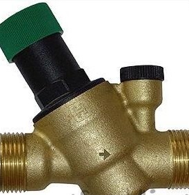
7. Honeywill Pressure Regulator
8. Pressure gauges 2 pcs
9. Coarse filter
10. Fine filter (10 microns)
11. Ball valve 1 \ 2 "8 pcs.
12. Pressure switch 2 pcs
13. Dry running relay
14. Dashboard lighting for 6 places
15. Automatic machines for 6 amperes 3 pieces
16. Indicator lamps for 220V, color, 3 pcs.
17. Water meter (used)
18. Flexible hose 1 \ 2 “2 meters
19. Fittings, adapters, clamps (as required)
There was already a water well at the customer’s site, but only builders used it, periodically lowering the trickle pump there and pumping water into barrels.
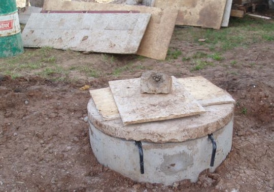
I had to start with the arrangement of the well.
The water supply well is located at a considerable distance from the house, about 8 meters. The well is made of concrete rings, the depth is 12 meters, the height of the water column is 1.2 m.
Plastic pipes of the water pipe with a diameter of 32 mm were laid underground, at a depth of 1.5 meters, insulated and additionally wrapped with a heating cable. Together with the pipes, an electric cable was laid in additional insulation to connect the pump. No photographs of this process were taken, because other specially hired people were engaged in this.
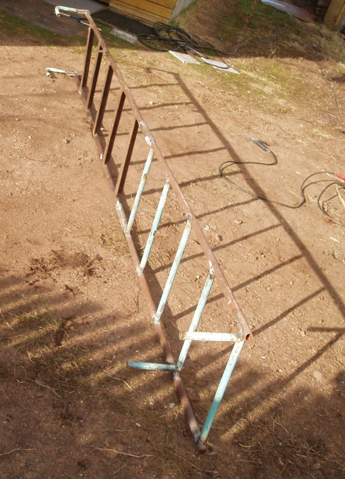
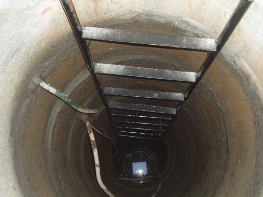
For the convenience of operation and maintenance of the pump, a home-made ladder was installed in the well, welded from pipe scraps, corners and fittings.
After that, a pump, a hydraulic accumulator, a pressure regulator, pressure gauges, pipes, fittings, adapters, pressure switches, and other spare parts necessary for installation were purchased.
Due to the fact that 99.9% of the pumps sold in our stores differ only in price tags and labels, and are made in the same factory in the Middle Kingdom, the pump was selected based on the following parameters: price, ease of connection, availability of protection and the maximum period guarantees.
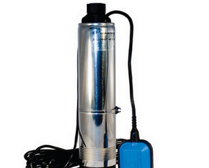
A 700W centrifugal submersible pump was purchased with an integrated water level sensor (frog) and a 3/4 ”connecting fitting. The maximum height of water rise is 50 meters. I don’t indicate the name and brand, I am an adversary of advertising.
About this one.
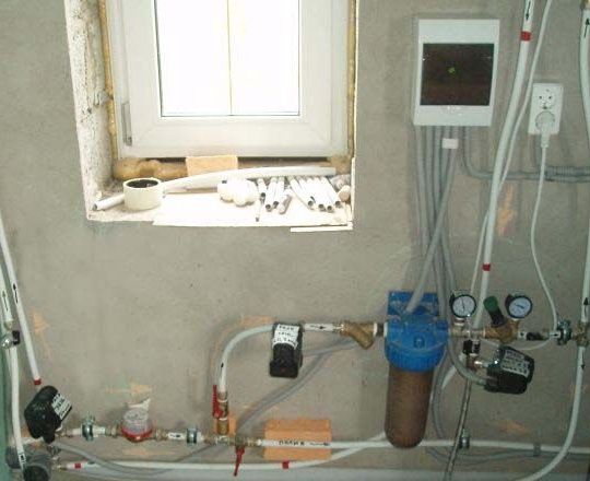
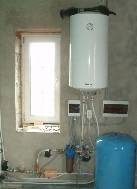
Installation of the system, it was decided to do directly on the wall in the utility room of the house.
Pipes and equipment are attached to the wall using clamps.
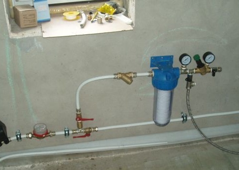
As you can see in the next photo, the entire water supply system is mounted in series, while the whole process of its operation is well traced. Markers marked with arrows marking the direction of the movement of water on the metapolar tubes. Subsequently, this greatly facilitates the operation of the system and its repair even by an untrained user.
On the pump itself, a check valve is installed in the well, which prevents the drainage of water from the pipes back into the well. Also, the pump has a water level sensor (frog), which turns off the pump, if the water level in the well drops below 50 cm.
Water from the well (see photo) enters the system input, where a protective relay is installed to limit the maximum pressure in the system. This relay is configured to shut off at a pressure of 5 kg / cm and is set so that the pump does not fail during overload (if the filter becomes clogged, the valve is accidentally closed).
Next comes the water meter. It would seem, why in a stand-alone system a counter? But it is needed, and installed in order to quickly control the amount of water pumped out of the well in a day.
As was established experimentally, the minimum debit of this well is 0.7..0.8 m3 per day in winter, and the maximum 2.0 ... 3.0 m3 of water in summer. What can you do, such a "waterless" place, you have to save.
Then, a non-return valve is installed on the pipe, followed by a “dry run” relay, which is activated when the pressure in the system is less than 0.5 kg \ cm, if a leak occurs in the system or air enters the pipes.
Next come the coarse filter (mesh) and the filter for fine water purification. Then a pressure gauge is installed showing the pressure in the accumulator, then a pressure switch, and a pressure regulator. A pressure gauge is installed behind the pressure regulator, showing the pressure in the supply line to consumers (sink, shower, etc.)
The pressure switch turns on the pump, it works if the pressure in the accumulator becomes less than 2.0 kg \ cm, and turns off at 4.0 kg \ cm.
The pressure regulator in this water supply system is a must. It is this device that allows you to economically use water, avoiding peak loads and draining the well. Without this device, for example, 100 liters of water was only enough for a short shower, and now you can use the water for several hours before the pump turns on and starts pumping water into the system. The pressure regulator is designed to maintain the minimum pressure necessary for their normal operation in the water pipes of consumers, regardless of the inlet pressure level.
Empirically, it was found that for the operation of the washing machine and for the shower, 1.5 kg / cm is enough, and this is more than enough for washing hands and the toilet. But now, no matter how wide the consumer’s tap is open, he will not be able to use the water jet more than the value set at 1.5 kg \ cm. It’s very convenient, you know, especially for city guests who do not know how to save water.
The electrical part of the water supply system is installed in a standard dash-rail with six positions, consists of three switches (conventional circuit breakers 6A) and three indicators.
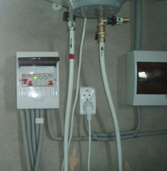
The photo clearly shows: the B1 power switch, the B2 pipe heating switch, the power indicator (green), the pump operation indicator (blue), the alarm indicator (red), and the forced B3 pump switch (in case of water pumping or watering).
Here is the wiring diagram of an autonomous water supply system.
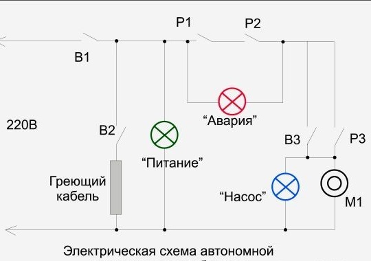
P1, P2 are the contacts of the protection relay and the dry-running relay. P3 - pressure switch, M1 - pump.
Installation of the water heater is carried out according to the instructions attached to it, according to the standard scheme and has no special features. The only addition is a tap for forcibly draining water from the water heater in case of repair or replacement of heating elements.
Over the entire period of operation, no repairs to the water supply system were required, except for the replacement under warranty of a rubber bulb in the accumulator. After curing, the old pear remained in reserve. There she is, on top of the water heater.