

Good day to all! This article will be devoted to lovers of electronics, robotics, as well as people with a non-standard look at the surrounding things!
So now I will try to describe the process of creation, assembly as clearly as possible the robot from e stuffing, namely, on Arduino! Go!
What we need:
Three-wire loop (3 pieces). It is advisable to take more authentic.
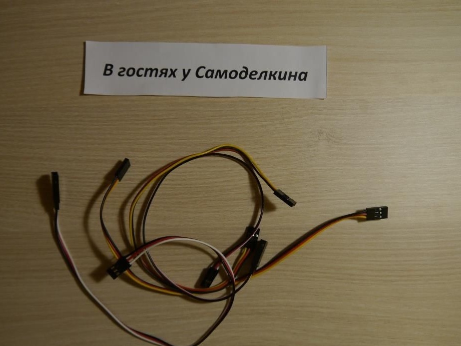
Ordinary wires
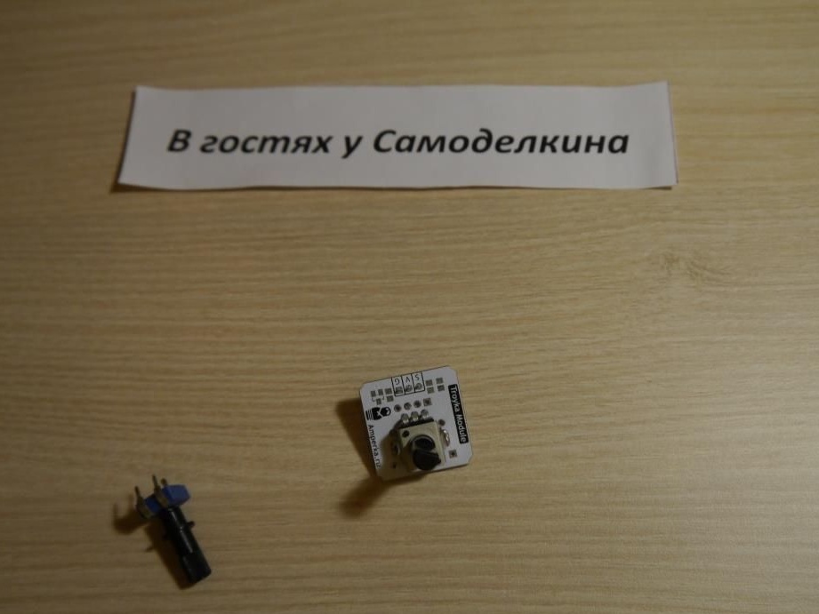
Potentiometers
Resistors (220 ohm)
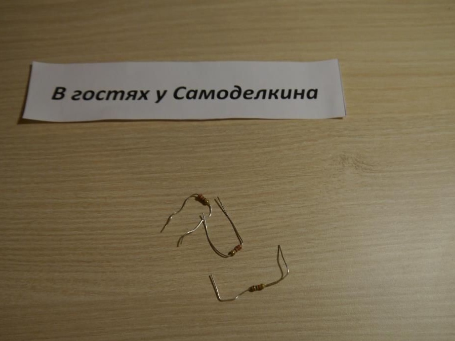
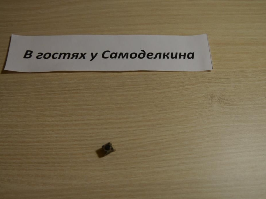
Button
Battery Compartment

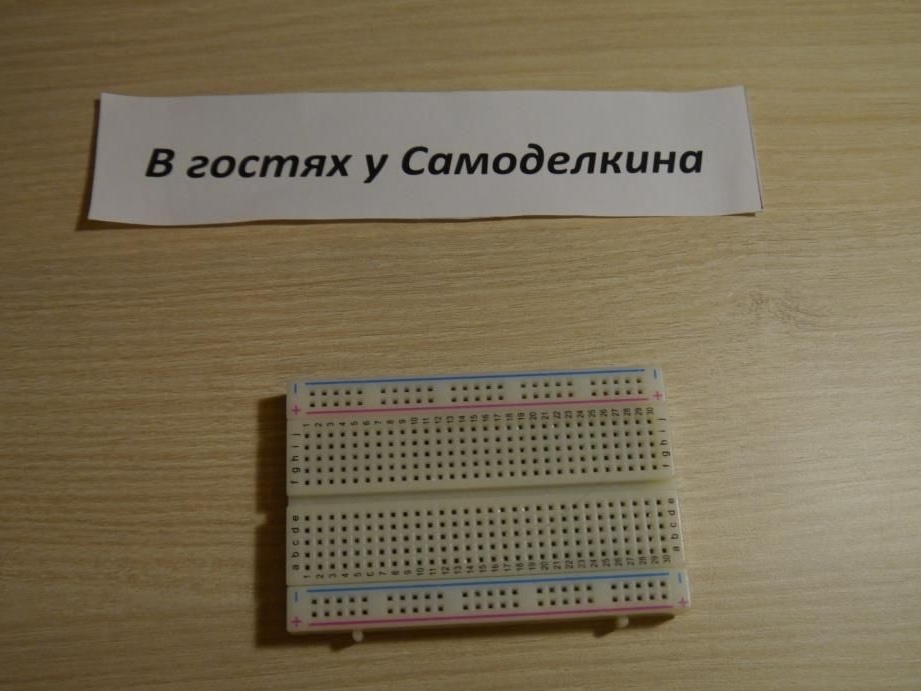
Bread board
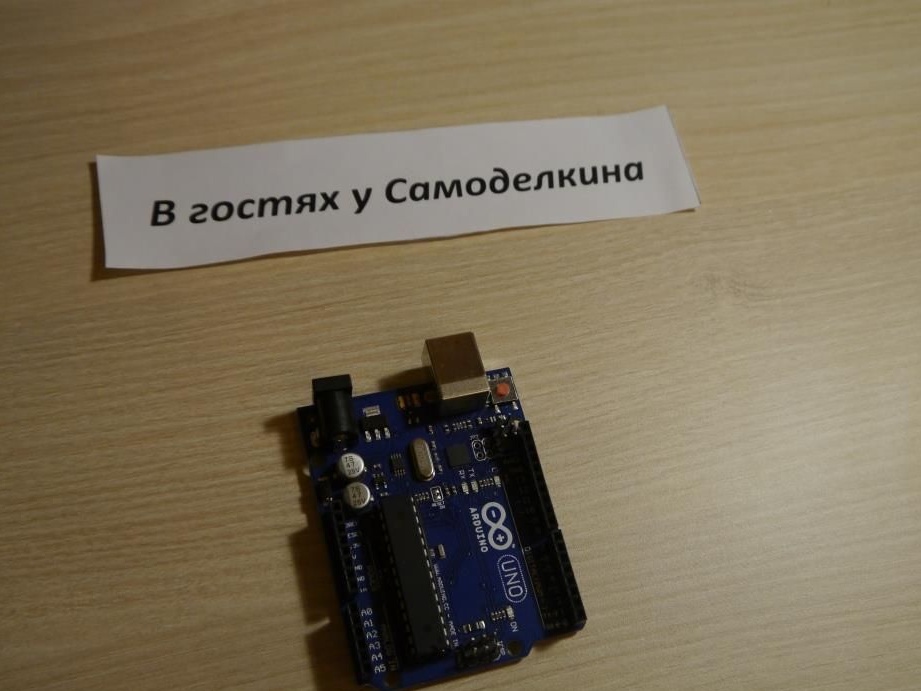
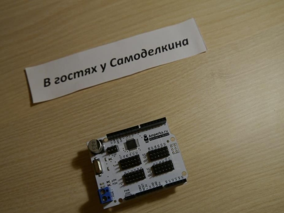
Well, of course, myself arduinka
And also an expansion board to it - something like MultiservoShieldto control a large number of servos
And any more constructor, which will be the basis of our robot, so it is advisable to choose "strong"
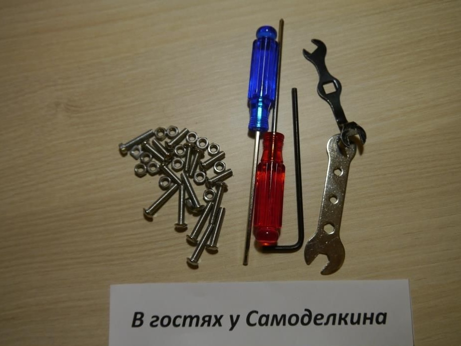
From the tools you will need:
A set of screwdrivers, keys, etc.
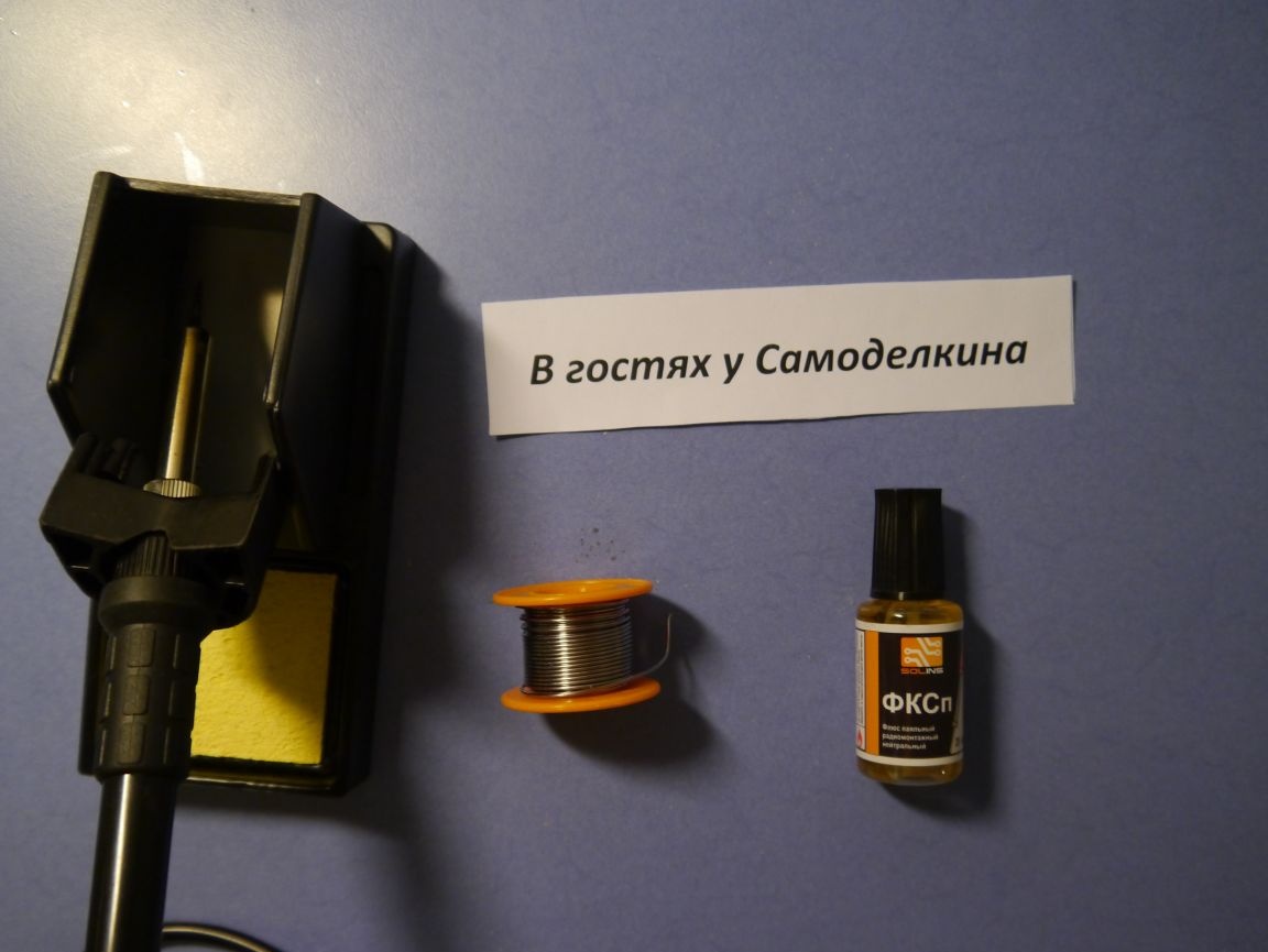
As well as a soldering iron, solder and flux
Well, let's get started!
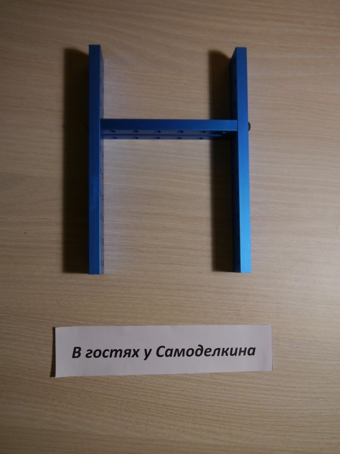
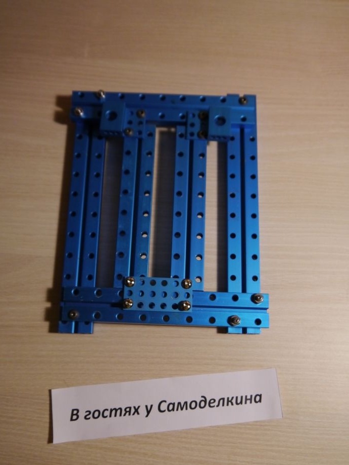
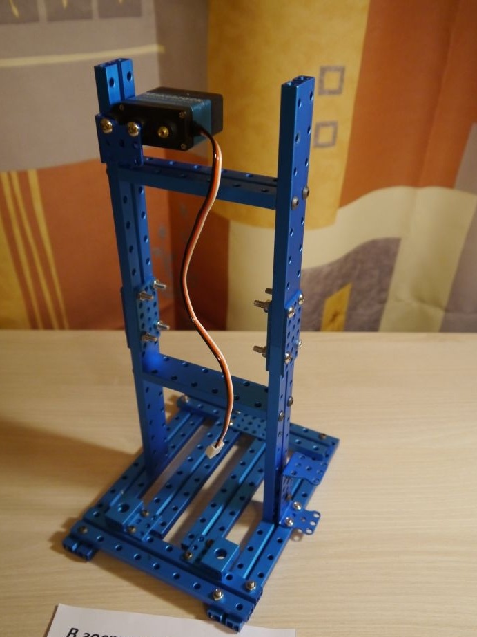
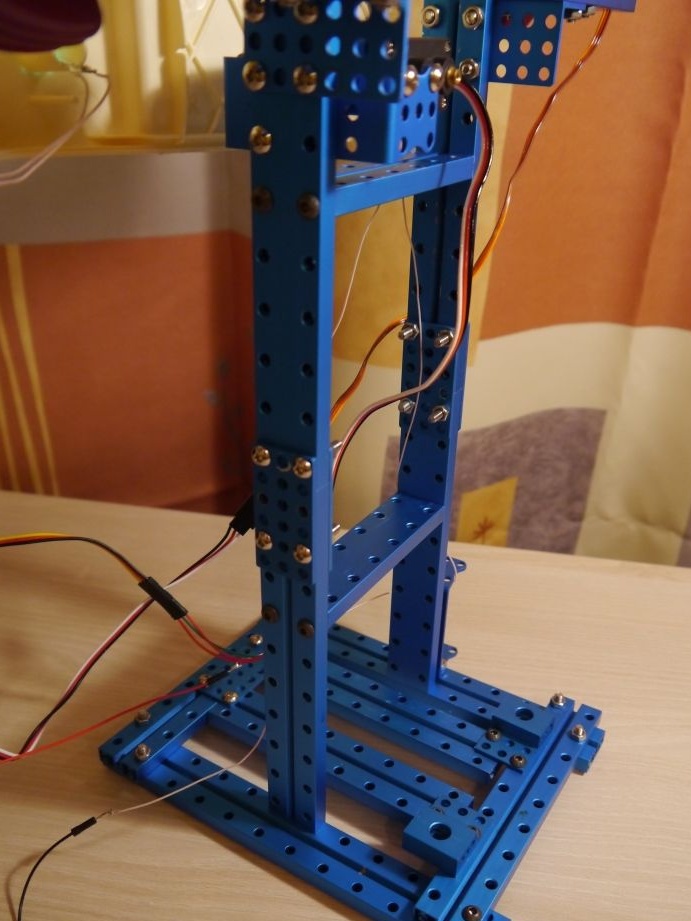
Step # 1. Fabrication of the main frame
To start, collect the "two letters H" It looks like this:
Then some construction on which our robot will stand. It’s not at all necessary as in the picture - at your discretion .. I did it this way:
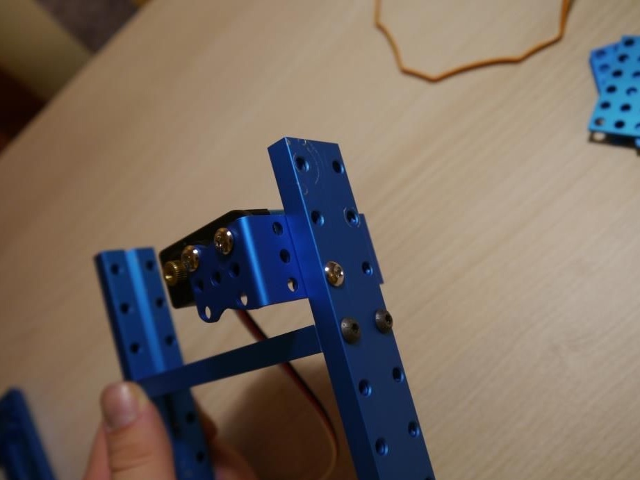
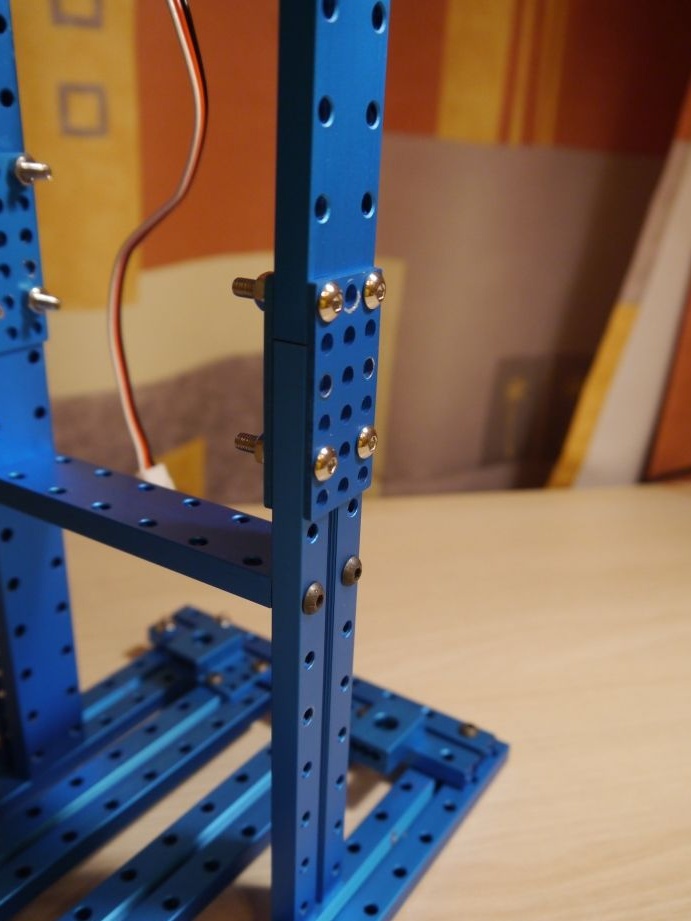
We install our "N" on the support
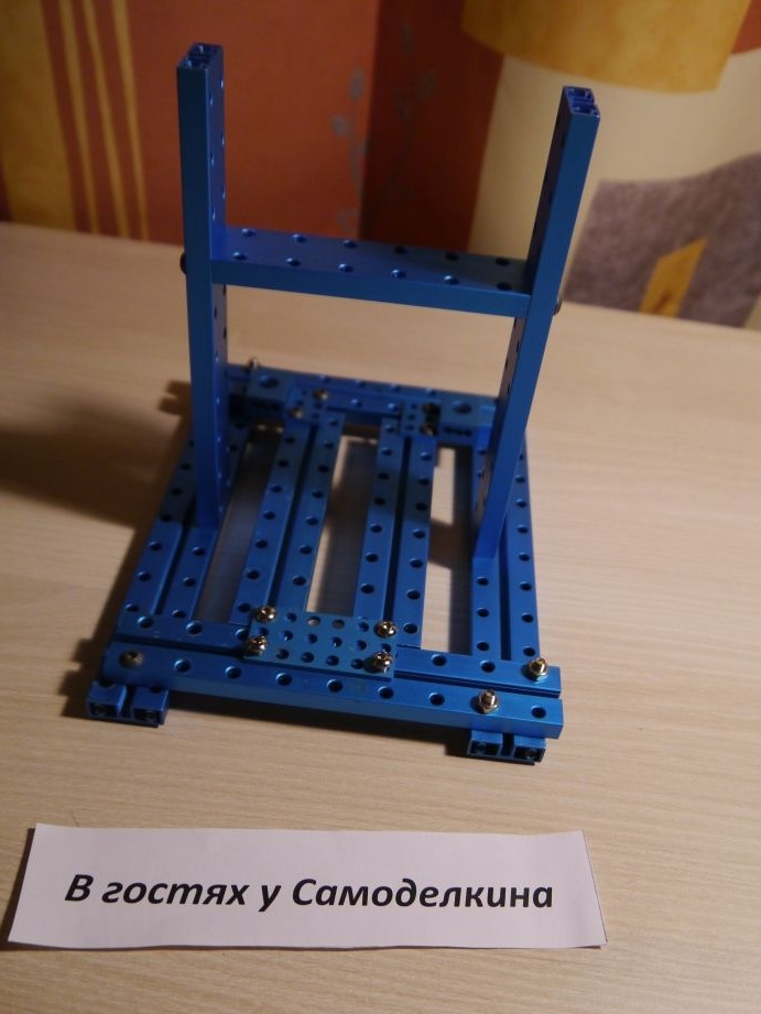
From below we tighten the bolts
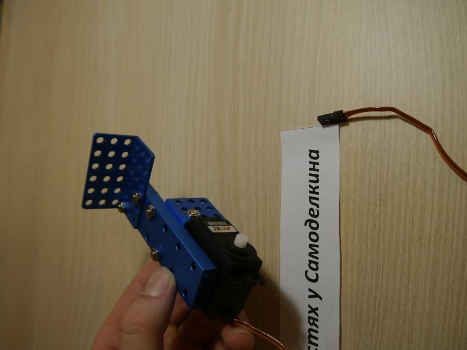
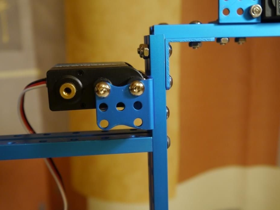
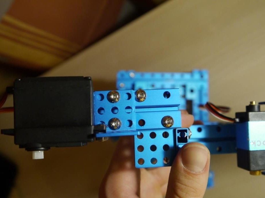
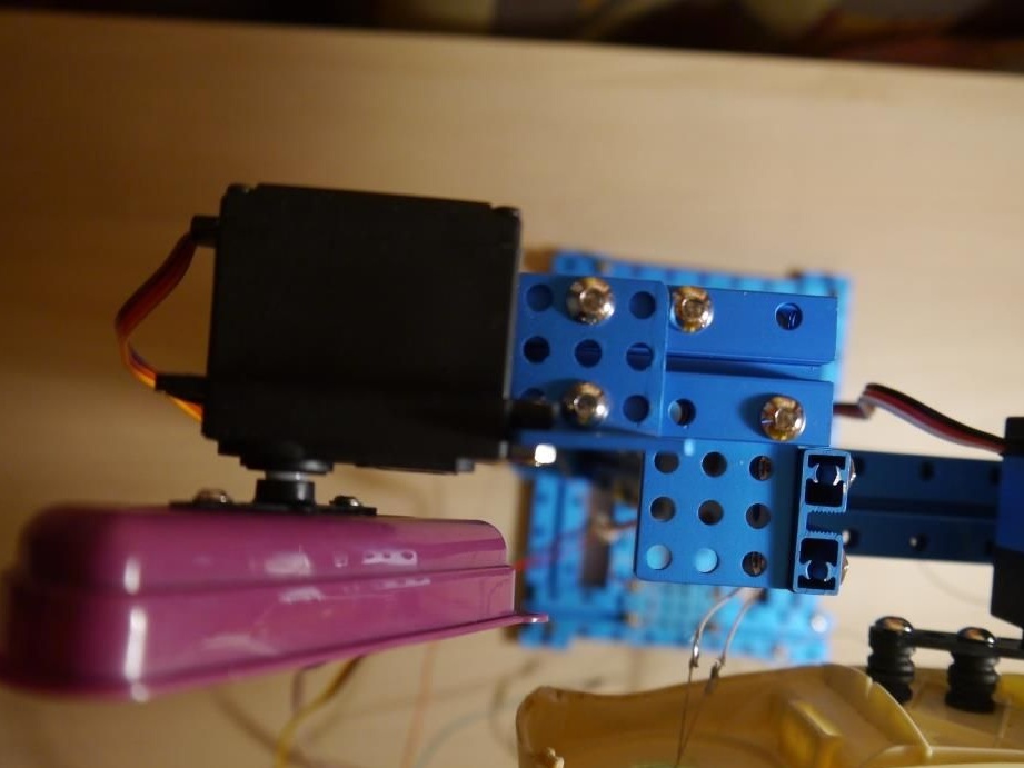
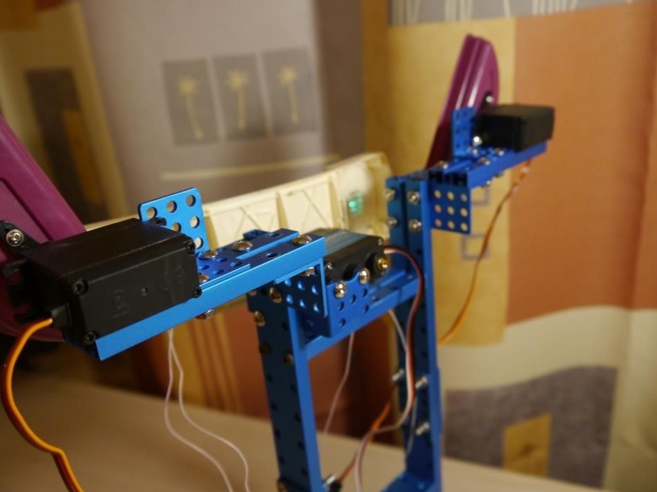
On the other "H" we fix the first servo, which is responsible for turning the heads of our future robot
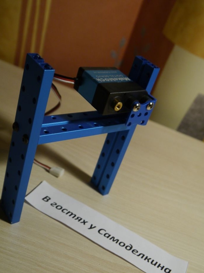
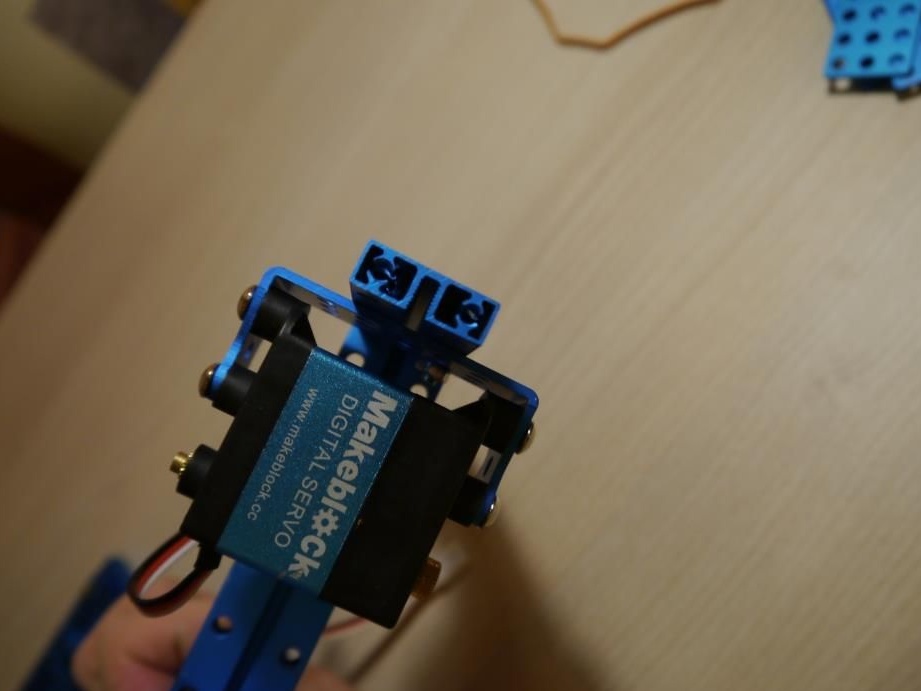
It turns out something like the following:
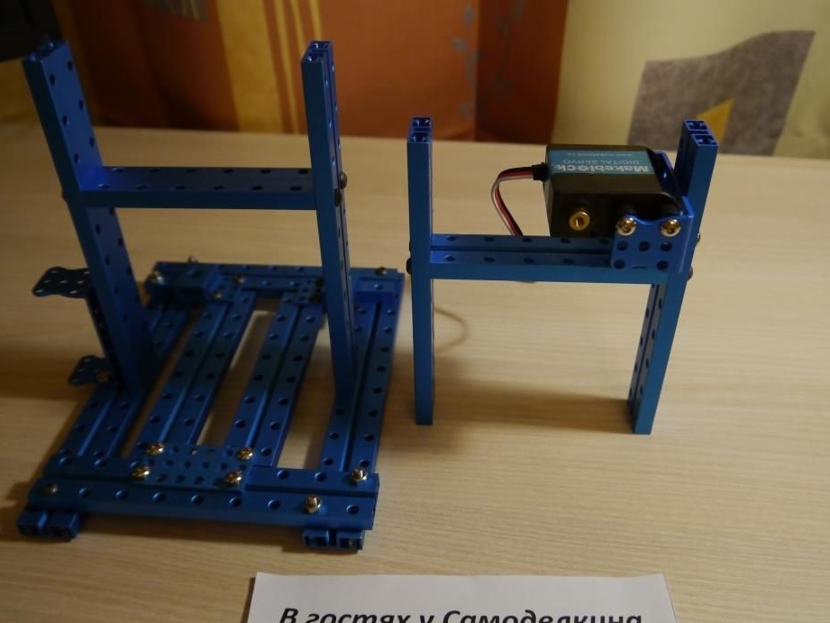
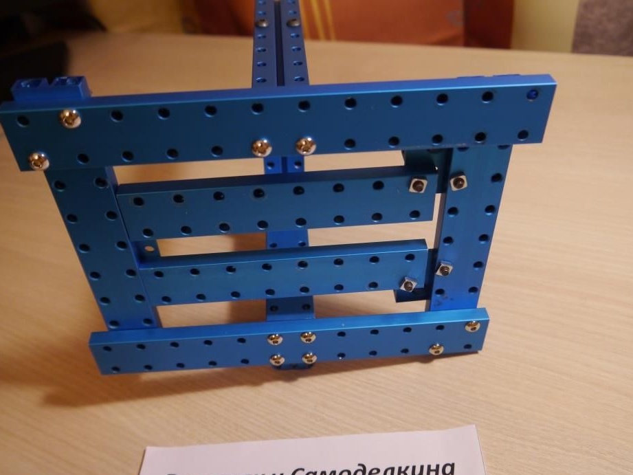
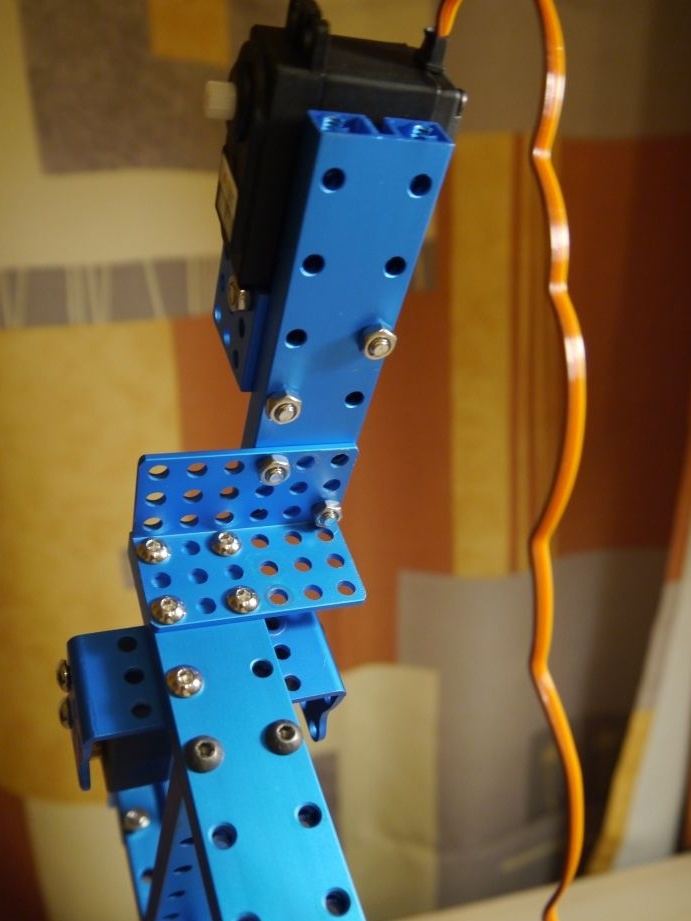
Almost the frame is ready! It remains to fasten these two structures with metal plates and give the robot height!
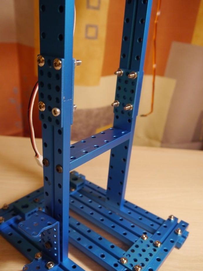
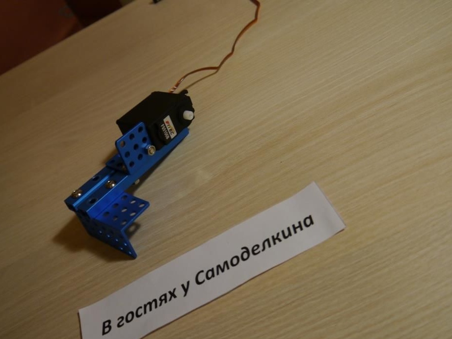
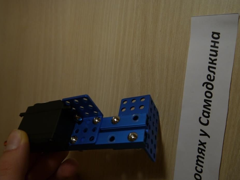
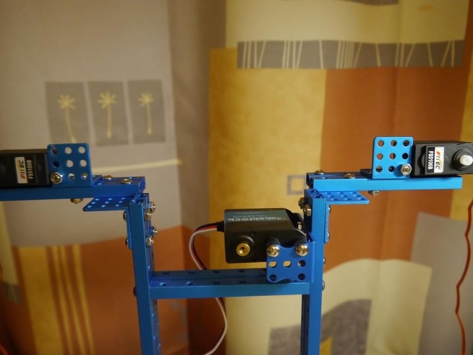
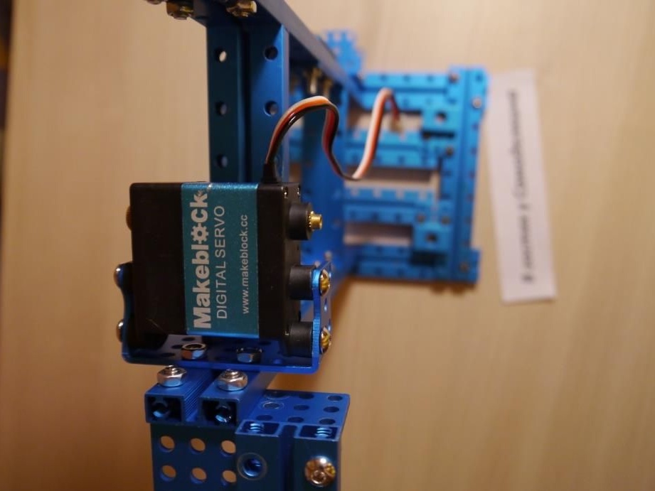
Step # 2: Making a frame for future robot ears
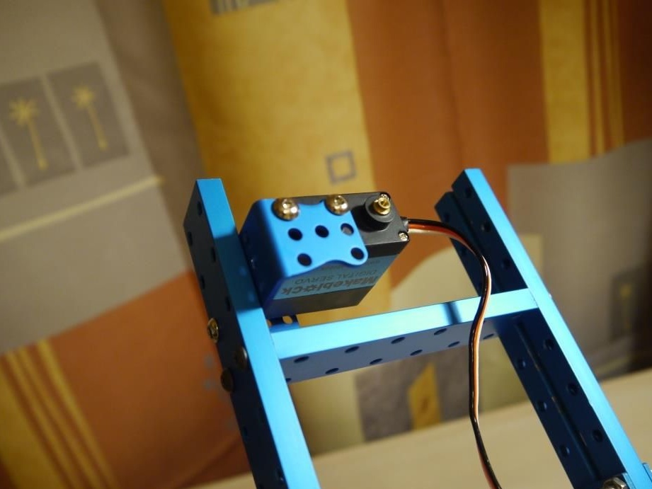
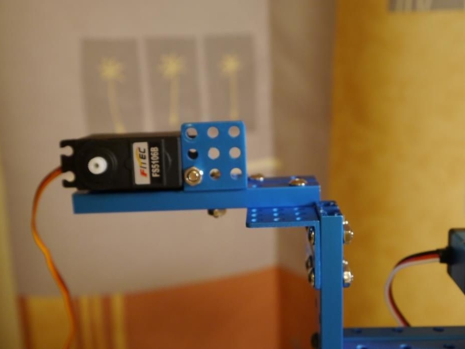
To do this, we need to assemble two similar structures and fix the servos on them, as shown in the figure:
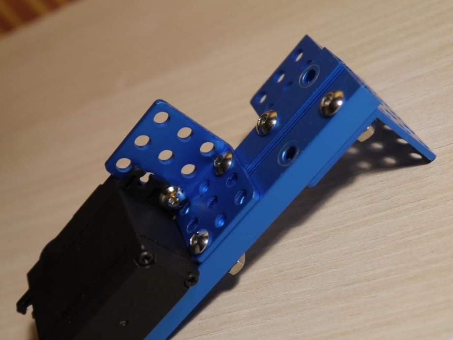
Then, using bolts and nuts, connect to the main frame. It will turn out the following:
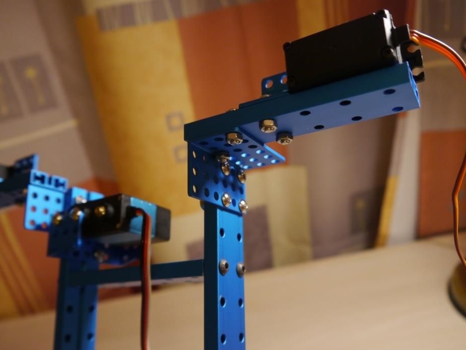
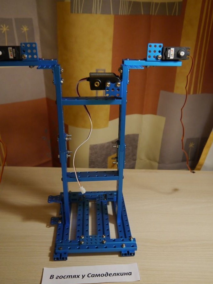
View from above:
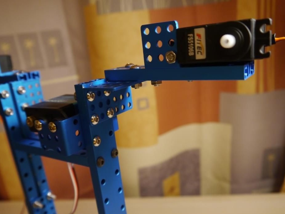
Well, a certain prototype of the robot is almost ready! Move on..
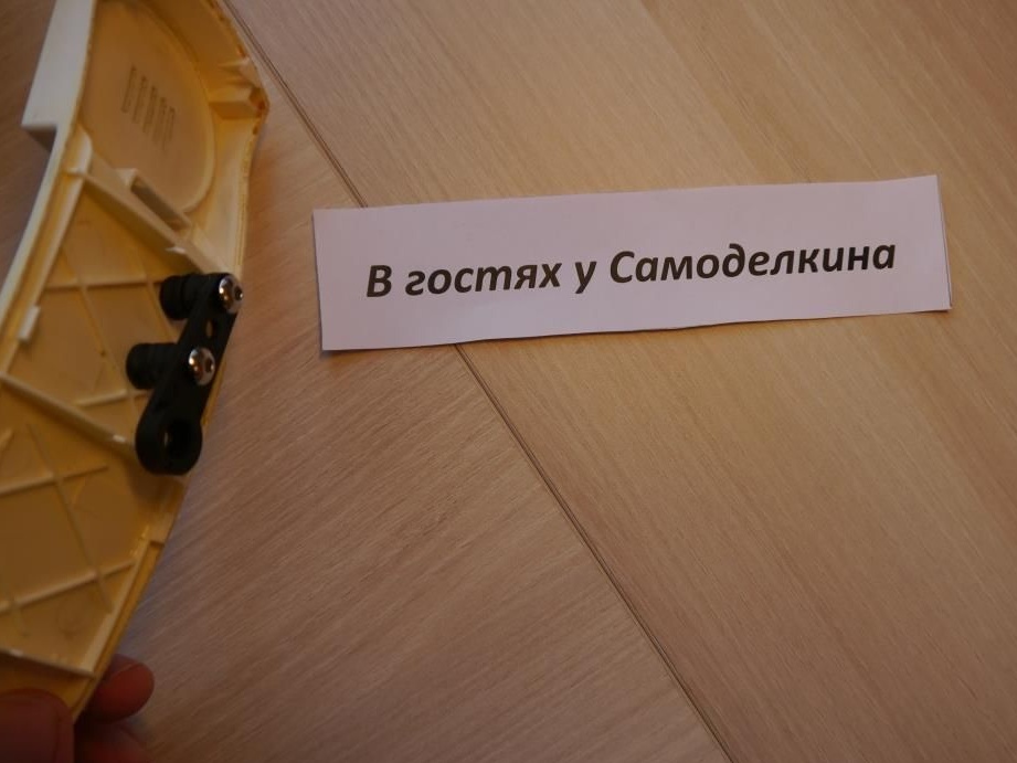
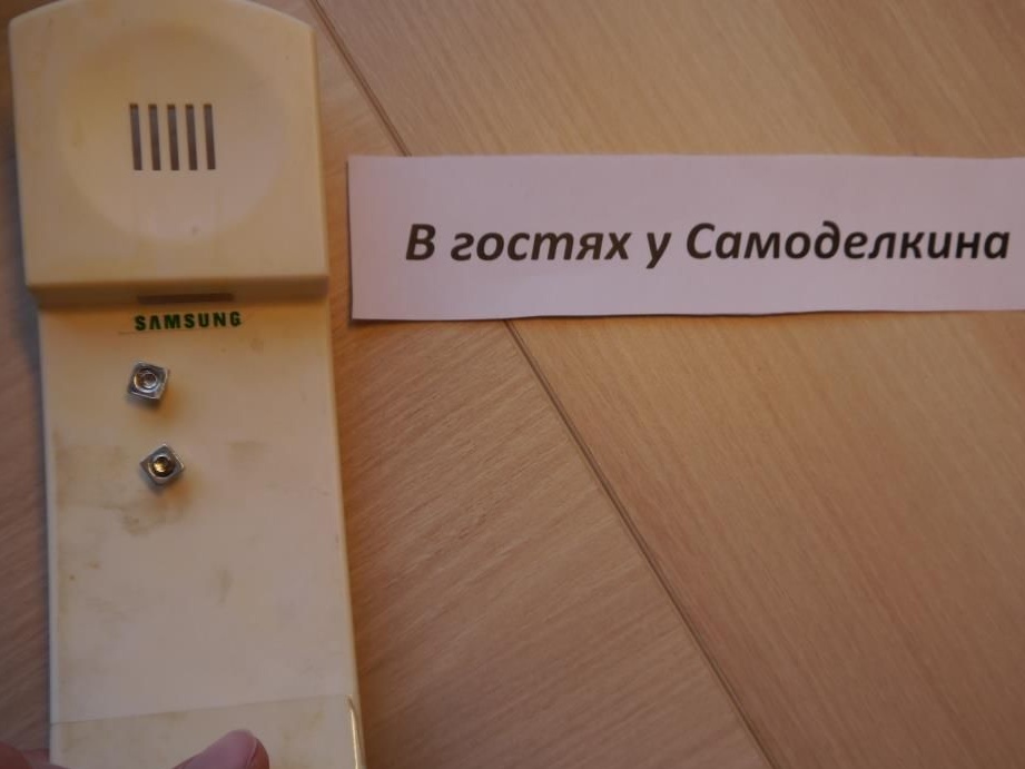
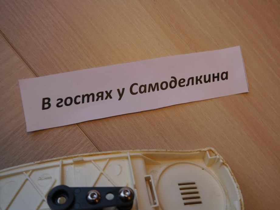
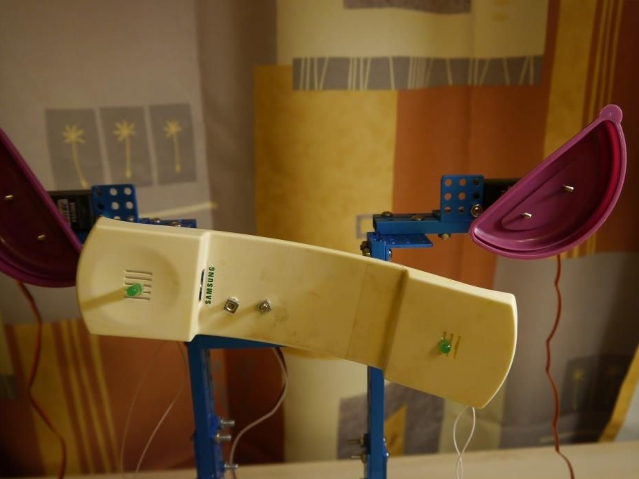
Step # 3. Making eyes and the whole head of our robot!
For this, I used the old handset from the intercom. Personally, she reminds me of a face! See more ..
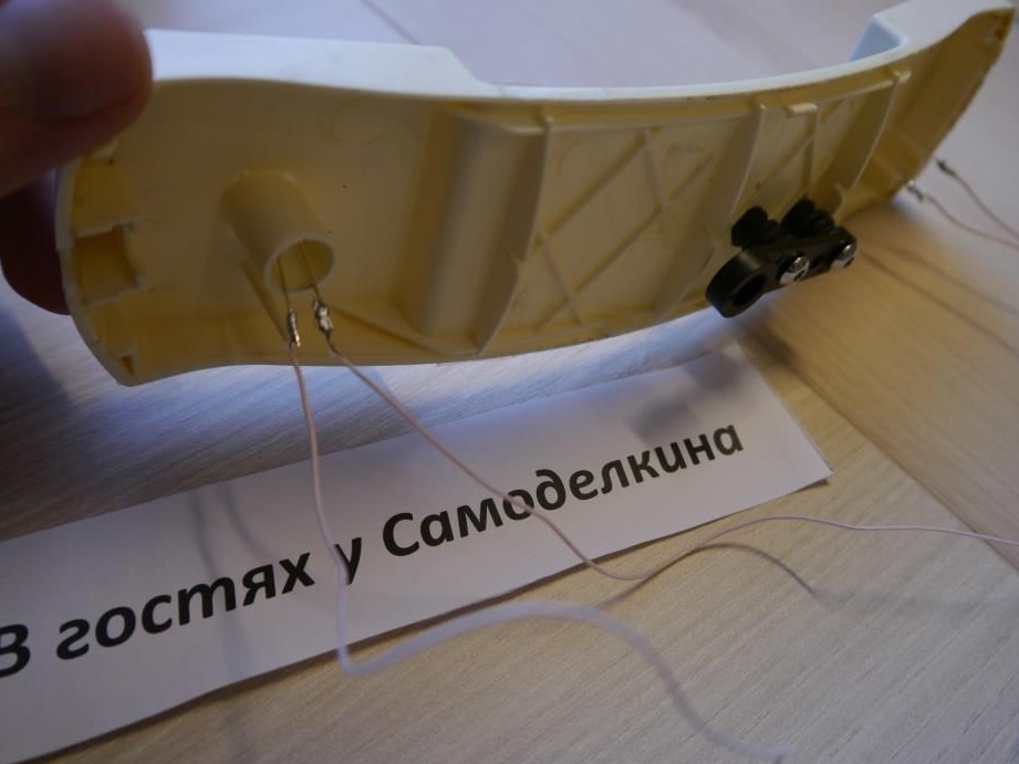
We make two holes and fasten the rocker for the servo to the tube
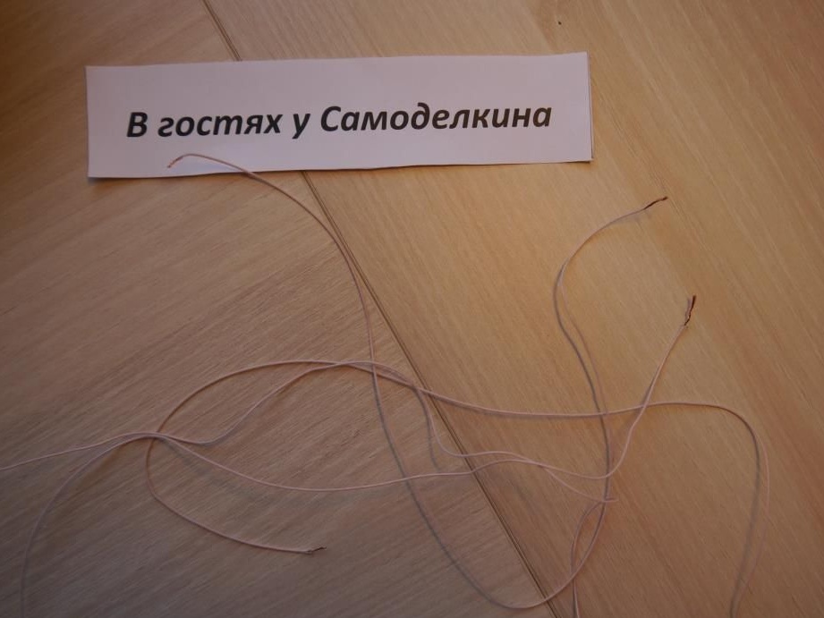
We immediately glue the LEDs on the sides and solder the wires to them
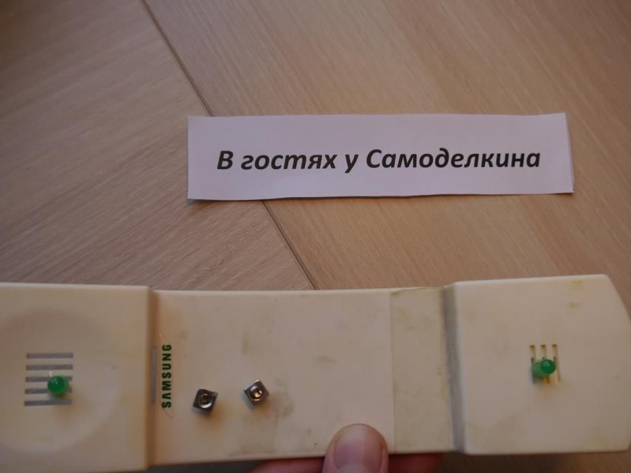
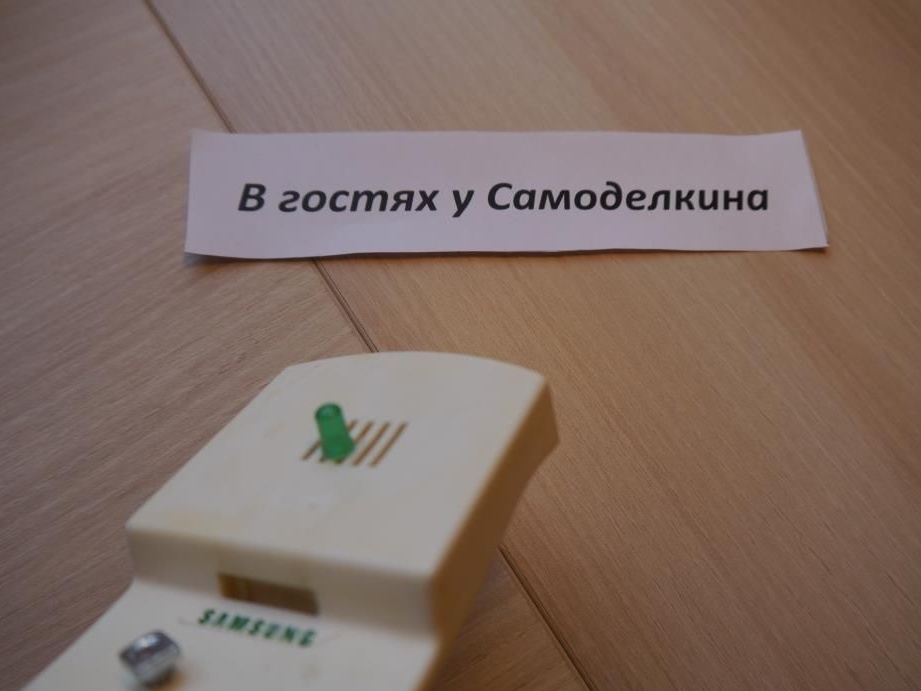
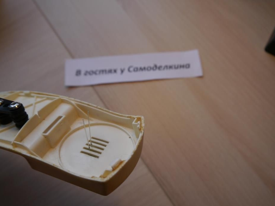
I used thin ones:
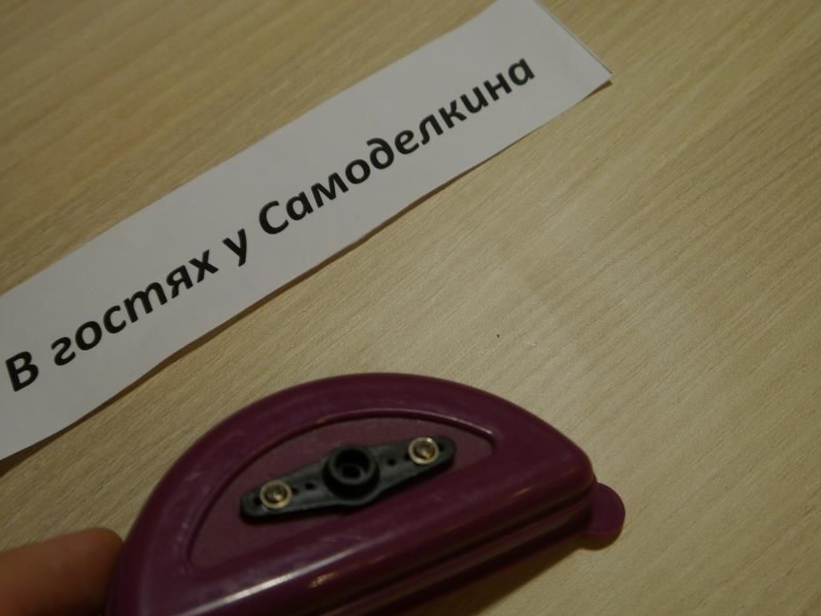
That's what happened!
Step # 4 Making Ears
We will use ordinary caps from small boxes
Also fasten the rocking chairs for serv

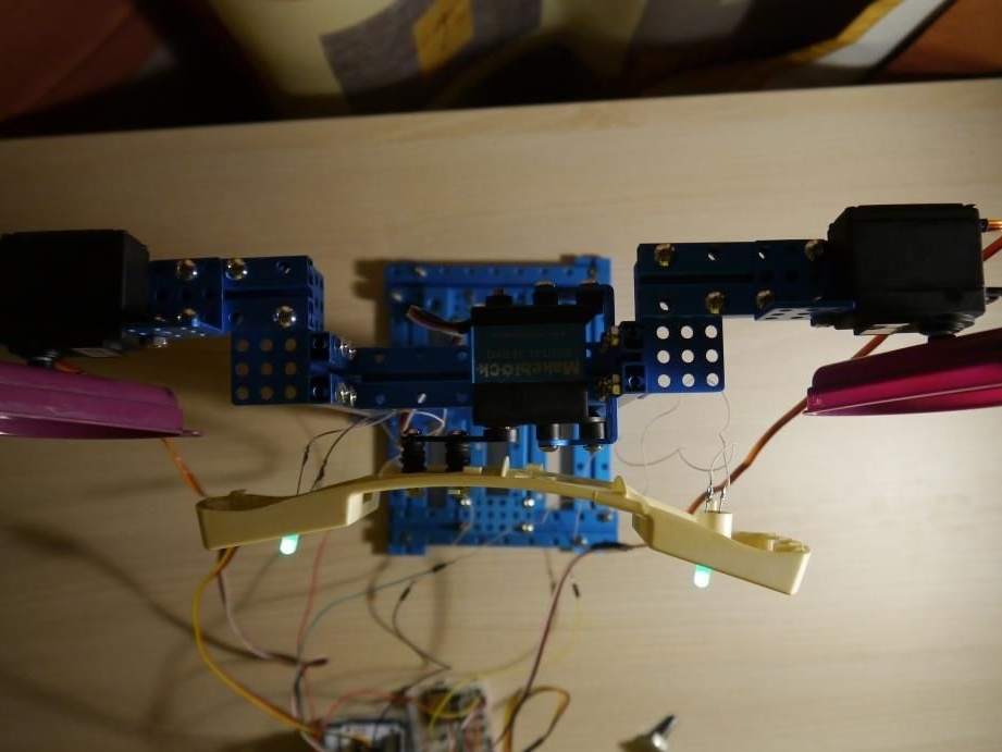
Now we boldly fix the parts of the body of the robot on the servers
Like this:
View from above:
Back:
In principle, you can enjoy the robot now, but we will complicate the task .. We will turn the eyes and ears of the robot using potentiometers and our arduinka
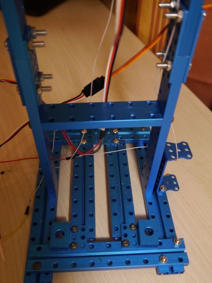
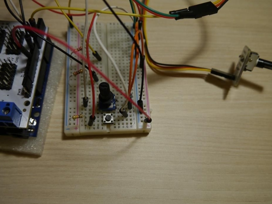
Step # 5 Electronics
Combining the arduino with the multiservice shield, we insert a three-wire loop from each servo to the pins 9, 10, 11 (Left ear, Right ear, Cent, if you put the robot facing us)
Then on the breadboard we install a potentiometer, a button, resistors .. It will look like this, ugly of course, but the main thing works)
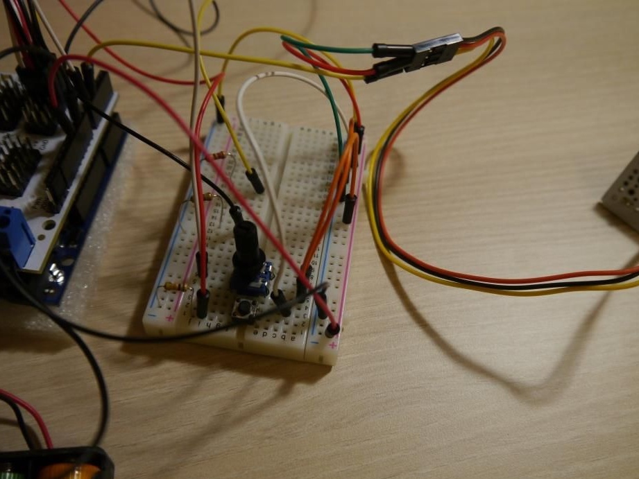
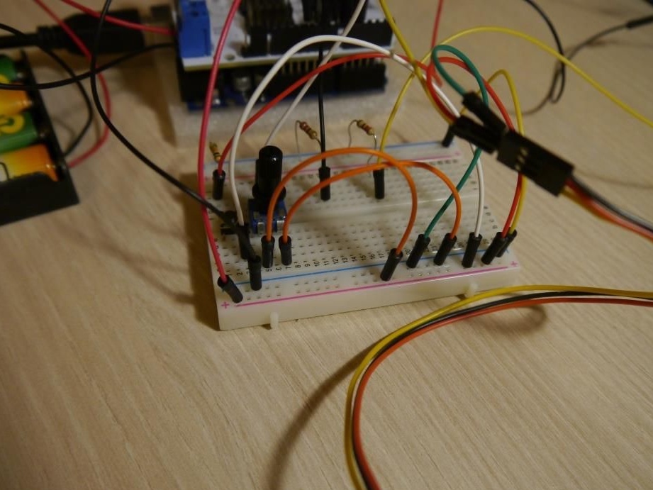
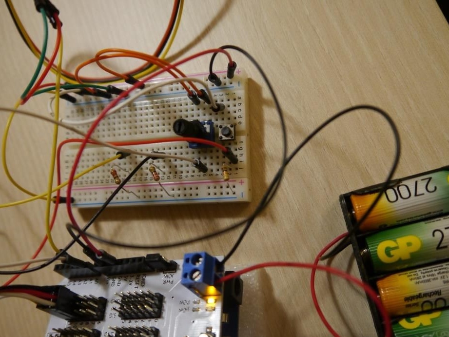
In details!
How to install the button:
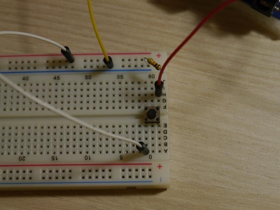
Where the white wire is power, Red is the digital input of microcontroller No. 6, and the resistor goes to ground (yellow wire)
How to install a potentiometer:
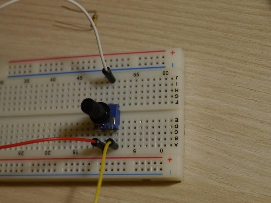
Red wire - power, Yellow - earth, White - analog input of microcontroller No. 0 (we connect another potentiometer in the same way, only analog input of controller No. 1)
We also install resistors for LEDs on the board:
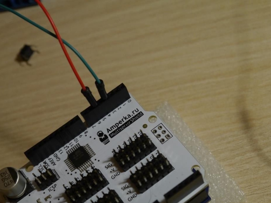
current will be supplied from 3 and 5 pins of the arduino, and will come through the yellow and black wires and through the resistors go to the ground (GND of the controller)
Well, basically everything, we are done with electronics! It remains only to download the next sketch and play with the robot !!
#include
#include
Multiservo myservo1;
Multiservo myservo2;
Multiservo myservo3;
int b, k1, p1, p2;
int A = 0;
int i = 0;
unsigned long m2 = 0;
unsigned long m1 = 0;
int r1 = 70;
int r2 = 110;
int r3 = 70;
 int h1 = 0;
 int h = 0;
void setup ()
{
  myservo1.attach (9); // left ear
  myservo2.attach (10); // right ear
  myservo3.attach (11); // eyes
      pinMode (6, INPUT); // button
      pinMode (3, OUTPUT); // eyes lights PWM
      pinMode (5, OUTPUT);
}
 void loop ()
{

    while (A == 0) // robot manual control loop
    {
        b = digitalRead (6);
        if (! b) k1 = 1;
        if (b == 1 && k1 == 1)
        {
              delay (10);
              b = digitalRead (6);
              if (b == 1 && k1 == 1)
                {
                 A is 1;
                 k1 = 0;
                }
        }
      p1 = int (analogRead (A0) / 6);
      p2 = int (analogRead (A1) / 6);
      myservo1.write (p1);
      myservo2.write (p1);
      myservo3.write (p2);
      analogWrite (3, i);
      analogWrite (5, i);
      if (millis ()> = m1 + 70 && h1 == 0)
      {
        i = i + 4;
        m1 = millis ();
        if (i> 250) h1 = 1;
      }

        if (millis ()> = m1 + 70 && h1 == 1)
      {
        i = i-4;
        m1 = millis ();
        if (i == 0) h1 = 0;
      }
    }
  while (A == 1) // robot autonomous work cycle
   {
       digitalWrite (13.0);
       b = digitalRead (6);
        if (! b) k1 = 1;
        if (b == 1 && k1 == 1)
        {
            delay (10);
            b = digitalRead (6);
            if (b == 1 && k1 == 1)
            {
                A is 0;
                k1 = 0;
            }
        }
      analogWrite (3, i);
      analogWrite (5, i);
      if (millis ()> = m1 + 70 && h1 == 0)
      {
        i = i + 4;
        m1 = millis ();
        if (i> 250) h1 = 1;
      }
      if (millis ()> = m1 + 70 && h1 == 1)
      {
        i = i-4;
        m1 = millis ();
        if (i == 0) h1 = 0;
      }
   if (millis ()> = m2 + 15 && h == 0)
   {
    myservo1.write (r1);
    myservo2.write (r2);
    myservo3.write (r3);
    r1 = r1 + 1;
    r2 = r2-1;
    r3 = r3 + 1;
    if (r1 == 110) h = 1;
    m2 = millis ();
   }
   if (millis ()> = m2 + 15 && h == 1)
   {
    myservo1.write (r1); // 110
    myservo2.write (r2); // 70
    myservo3.write (r3); // 110
    r1 = r1-1;
    r2 = r2 + 1;
    r3 = r3-1;
    if (r1 == 70) h = 0;
    m2 = millis ();
   }
   }
}
The code is rather big, but believe me it's worth it!
Briefly, what does this program do:
We have a button that is responsible for 2 states of the system: either we control the robot manually, or it carries out movements already registered in advance. When a button is pressed, the states change for us, and in the code, 2 cycles change among themselves, in which the corresponding commands are registered. The eyes of our robot gradually light up, become brighter and brighter, and then fade out. that is why we have dubbed the LEDs to the pins supporting PWM - pulse width modulation.
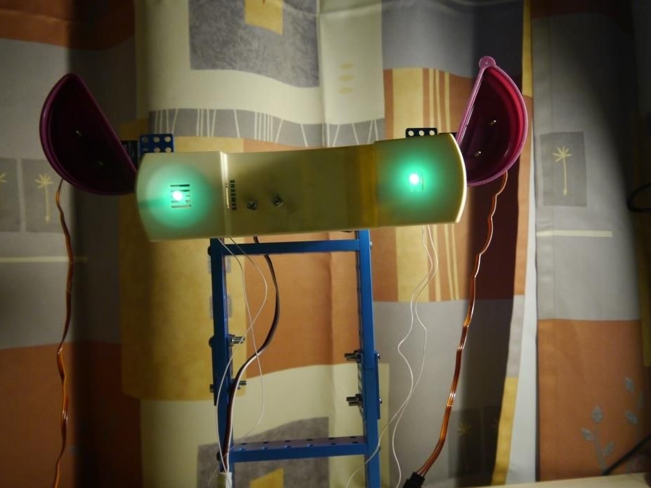
Photos of the robot:
Small video recording, how and what eventually turns:
In conclusion, I want to say that, of course, this robot can be brought to mind for a long time, but this is the taste of every person. Do it! Invent! Evolve! Good luck to all!