The flasher consists of a cover from the counter, two sawn-out plexiglass circles (organic glass), bolts ande "Fillings."
Tools and materials:
1. Curly screwdriver
2. Soldering iron
3. Cutter
4. Screwdriver
5. Glue
6. Nuts, bolts
7. Organic glass
8. Foil
Detailed description homemade
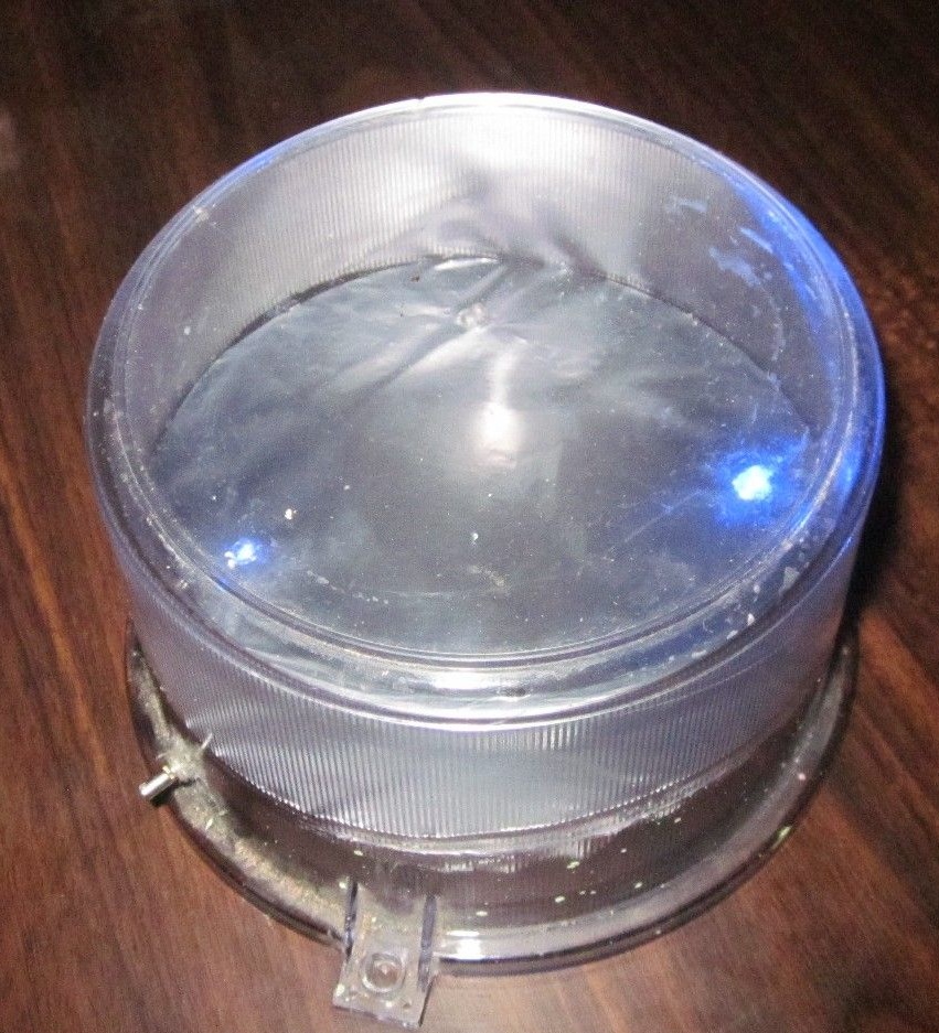
First, take the cover from the counter, of course, an unnecessary counter: smile:. Clean, wash, if necessary. We cut out a circle such that it enters the lid halfway and make holes for the LEDs. Depending on the number of LEDs, holes are made at your disposal. In my case, it turned out two LEDs.
Then, to enhance the illumination, we wrap the cut circle with aluminum foil, although in principle it is possible not to wrap, then the entire lid will glow.
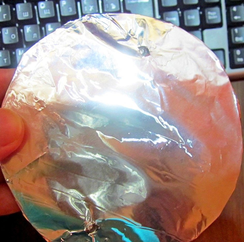
We insert a circle with a wrapped foil and glue the joints with glue gun or any other glue.
The next step is to collect the electronic "stuffing" of our emergency lights. Anyone who owns a soldering iron well will not have a big problem collecting such a small circuit.
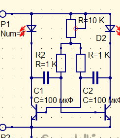
The circuit contains the following radio elements:
2 kΩ resistors
2 transistors BC337-25 of the n-p-n structure, but any low-power transistors of the n-p-n structure (Kt315, Kt3102, etc.) can be successfully used
2 capacitors 100 uF 10 V
Explanation of the scheme:
In the circuit, you can use any 3 V LEDs, with any glow, and you can also solder LEDs to the LEDs in parallel, of course, you can not solder infinitely, since you will need to increase the voltage. It will be quite normal to solder 2-3 LEDs in parallel on one LED, that is, if you solder two LEDs in total, you get 6 LEDs. Where R = 10 K, this is a 10 kilo variable resistor. The capacitors marked in the C1 and C2 circuit can be used with any capacity from 1 microfarad to 1000 microfarads and with a voltage of at least 10 V. Transistors are used any low-power, n-p-n structures. The supply voltage of the circuit is from 3 to 4.5 V, that is, the circuit can be powered from two 1.5 V batteries and up to 3 1.5 V batteries connected in series.
And now, as I assemble the circuit:
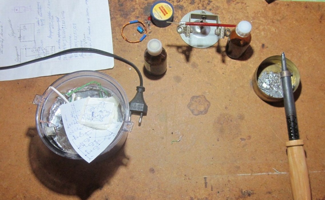
Preparation for work
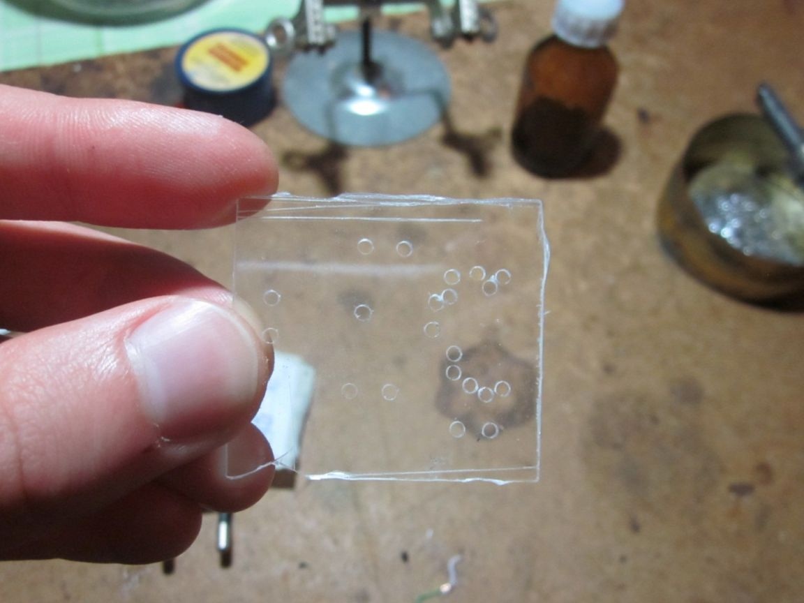
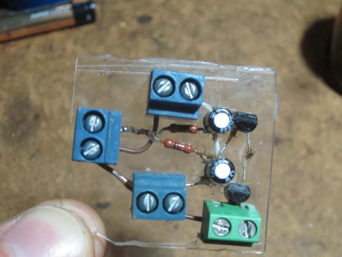
Here is my board on which the radio components will be soldered.
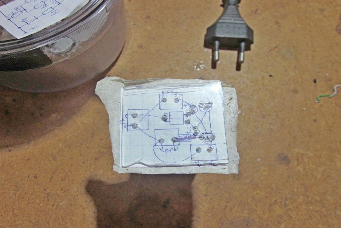
Here is a finished board with soldered parts. View from above.
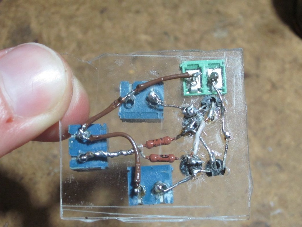
View from below.
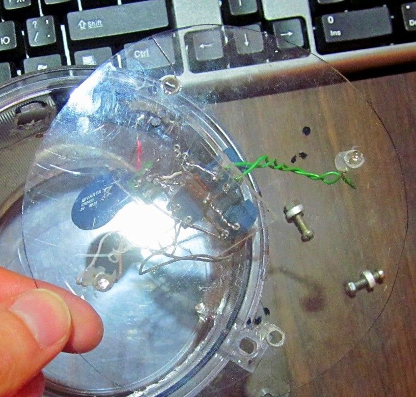
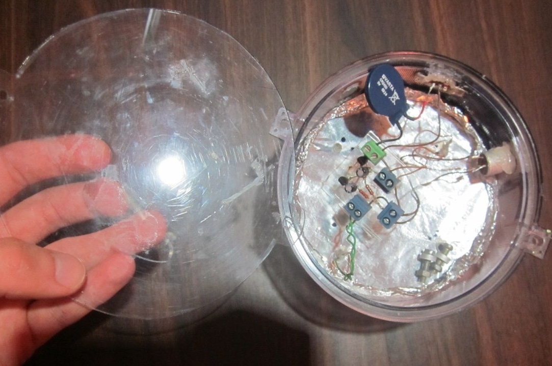
Now, after the assembled circuit, we put everything into the case. The circuit board with the radio elements can be glued to some wall.
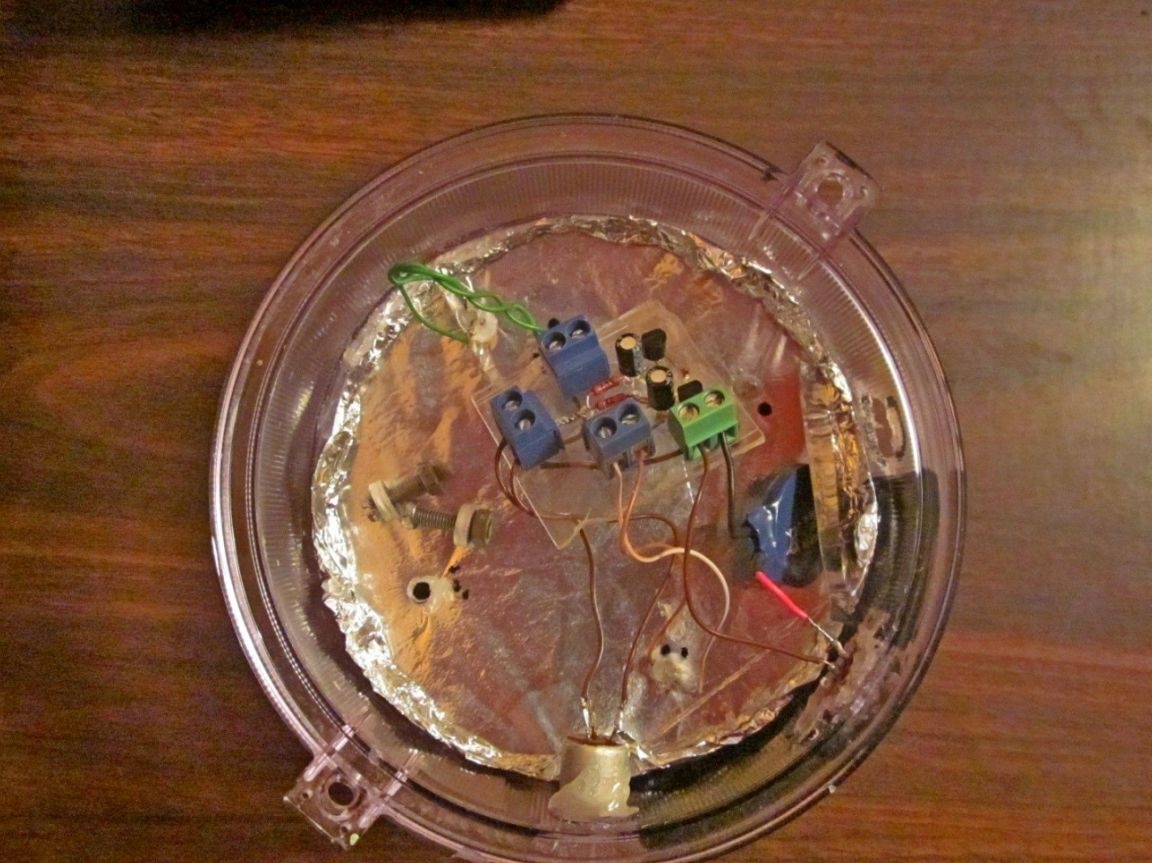
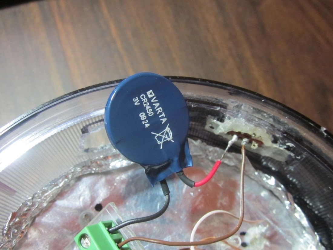
I made a hole for the variable resistor and put it in, then glued it with a glue gun. And in the breakdown of the power supply circuit, I connected a switch, and just like with a variable resistor I made a hole and glued it with glue gun. I put the CR2450 at 3 V. The battery is the size of a thumb on my hand.
Next, you need to cut the back wall from Plexiglass and make two holes in it as in the photo.
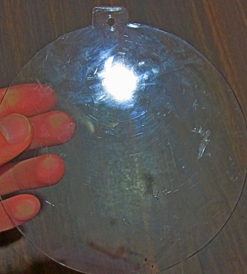
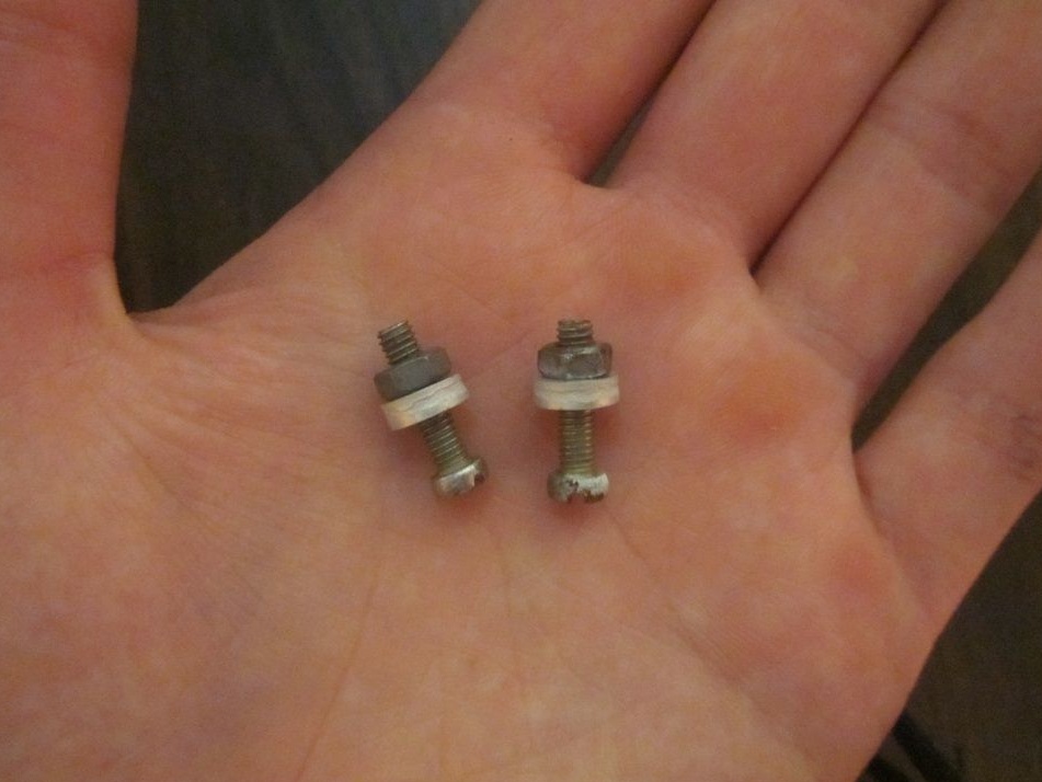
These holes are made for bolts so that you can fasten the back wall with the cover. And since there are two holes in the counter cover, we simply pass our bolts through the holes made in the back wall and the covers, then fasten the bolts with nuts. You can use the bolts with nuts and washers in the photo below.
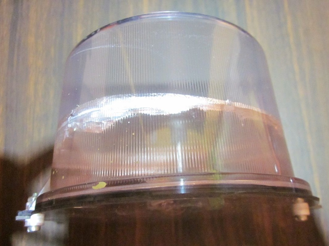
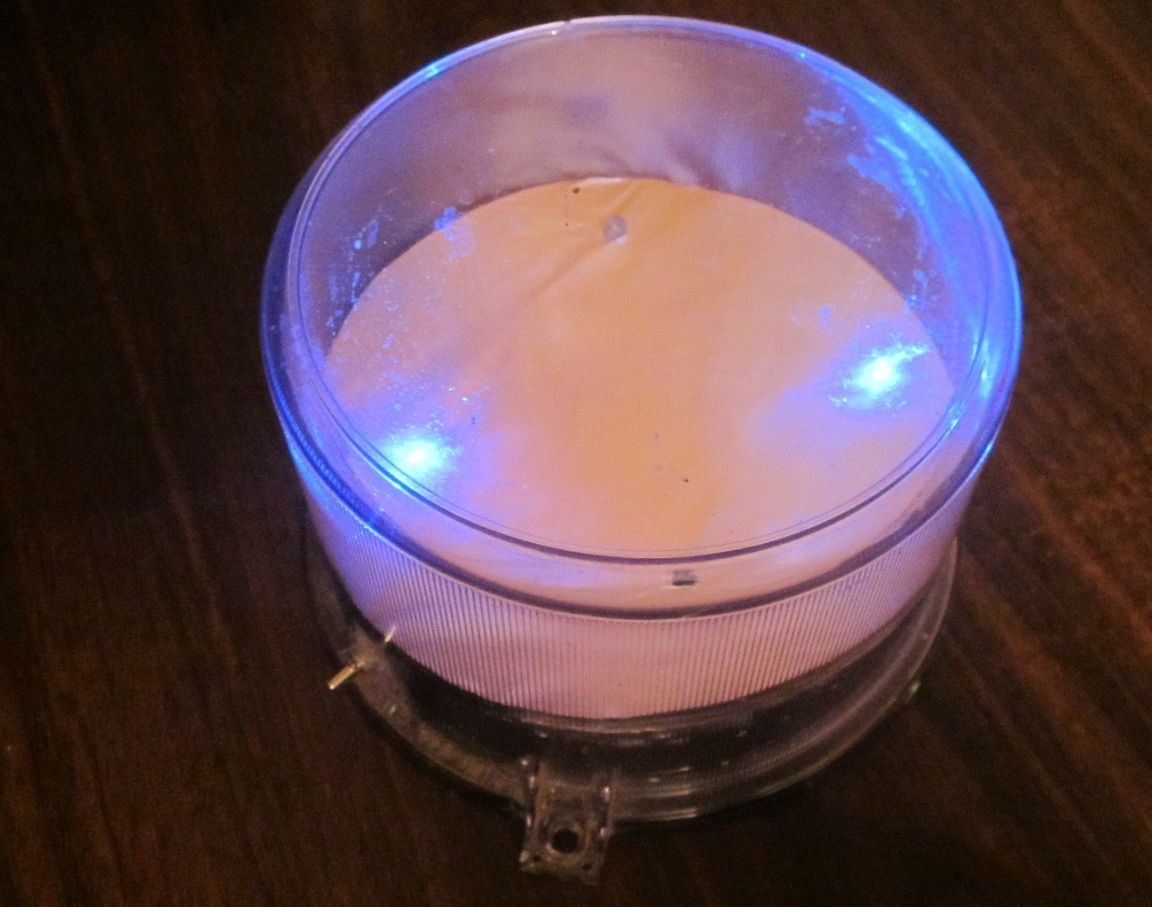
That's all, the flasher is ready for use.