

This article describes how do it yourself make from any electronic hours with an audible alarm clock timer to control household appliances.
A timer is a device that turns equipment on or off at the set time with its switching contacts. Real time timers allow you to set the response time at the set time of day. The simplest example of such a timer would be an alarm clock.
The scope of the timer is extensive:
-control of lighting devices;
-watering management home and garden plants;
-control ventilation;
- management of the aquarium;
- control of electric heaters and so on.
The proposed timer can quickly and inexpensively make even a novice ham radio.
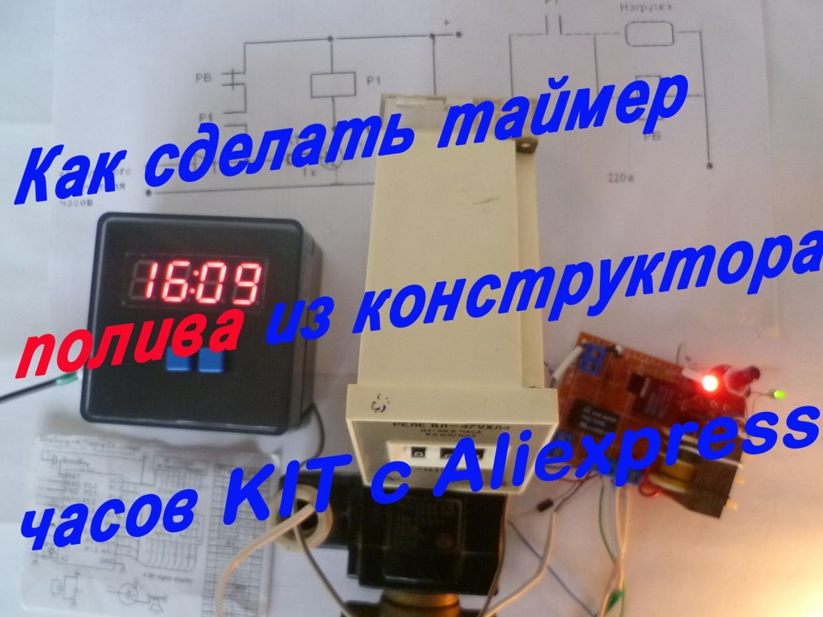
I made it based on the designer of watches. (How I collected this kit)
I needed to use a timer to control the watering of plants in the country.
See the entire manufacturing process in the video:
The list of tools and materials
- any electronic clock with an audible alarm;
-screwdriver;
- scissors;
soldering iron;
Cambridge;
- two relays for 12V;
-12V power supply from the adapter;
-connecting wires;
-folded textolite for printed circuit board or breadboard;
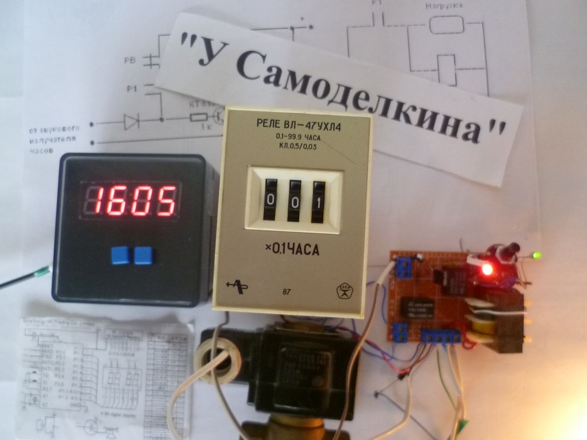
-time relay industrial or home-made;
-resistor;
KT815 transistors (or analogs);
-diode.
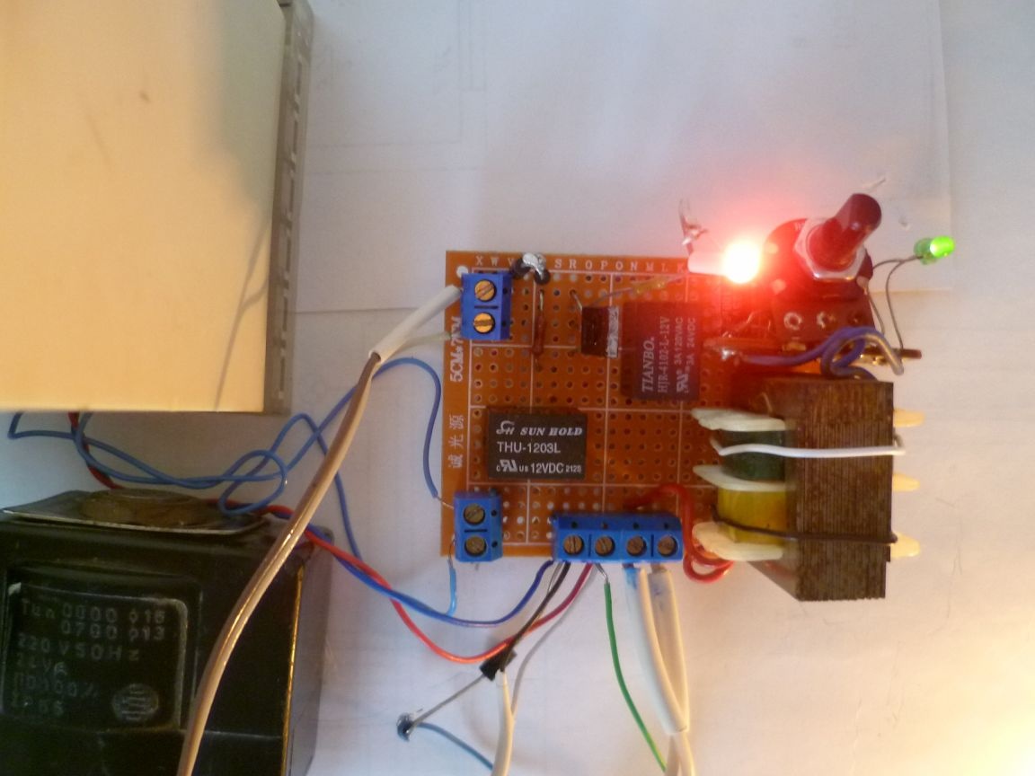
Step one. Wiring the timer board.
Timer circuit
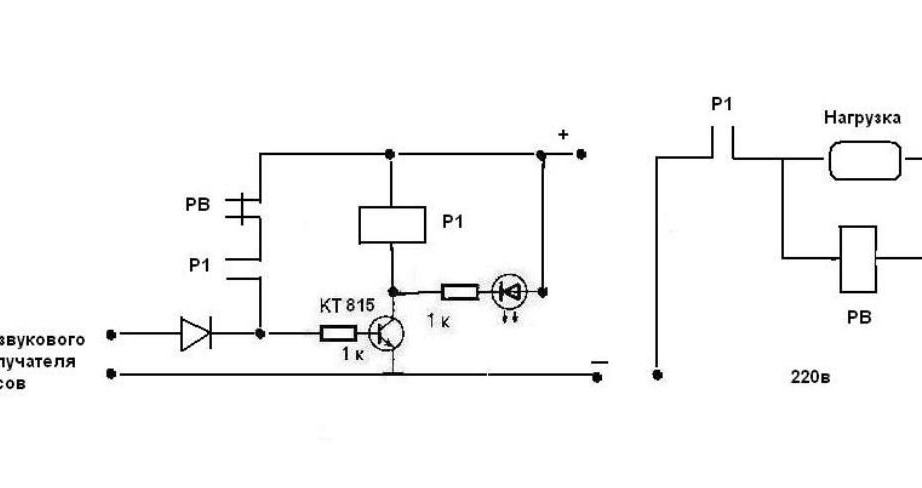
All that is needed is to solder the components to the breadboard according to the circuit diagram and solder the two wires from the piezo emitter of the clock. We assemble the simplest circuit with an intermediate relay and a transistor switch. When the first pulse of the sound signal is supplied from the clock, relay P1 turns on, the normally-open contact closes and turns on the load, simultaneously through the second normally open contact of relay P1 and the normally-closed contact of the time relay, relay P1 self-locks. Together with the load, the relay switches on;At the end of this time, the RV opens the contact and the relay P1 is de-energized, the load is off. The circuit is ready for the next cycle. The diode serves to prevent a reverse pulse in the clock circuit (any low-power diode can be used). LED to indicate load on. In this circuit, an intermediate relay with two normally open contacts is needed, but I didn’t have it — I applied two Chinese relays (the coils are connected in parallel). If the load is more powerful, then we must use relays with more powerful contacts. I had a 12V adapter, I installed its circuit directly on the breadboard. In principle, any low-power 12V power supply can be used.
If shorter, then the clock turns on the load and the time relay turns off after the shutter speed.
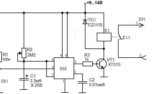
If you do not have an industrial timer, you can do it yourself according to a simple scheme. With an increase in the capacitance of capacitor C1, the operating time of the relay increases.
Step Two Check the timer.
My scheme worked the first time I turned it on.
It remains to set the alarm time. My watch has two alarm time settings. For my case, it’s enough to turn on the watering, for example, in the morning at 7 o’clock for an exposure of one hour, and in the evening at 20 o’clock to water again. When the watch buttons are pressed, sound signals are emitted, therefore, when setting up the timer circuit, it is necessary to de-energize to exclude false alarms. My watch has the “chimes” function - every hour from 8 to 20 hours, that is, you can use these signals, if necessary, in addition to the alarm clock. If you do not need it, the chimes function is disabled.
This is the design of the weekend. It was interesting to break in a new scheme, so everything was done quickly. In the future, it will be necessary to make a case and put a board and a timer there. It’s up to the beginner to make such a timer on his own without spending a lot of time and money. And where to apply them is up to you.
A couple of weekend nights and 75 rubles () went to all the work. The rest of the components I had were in stock.
Good luck to everyone in your endeavors!