

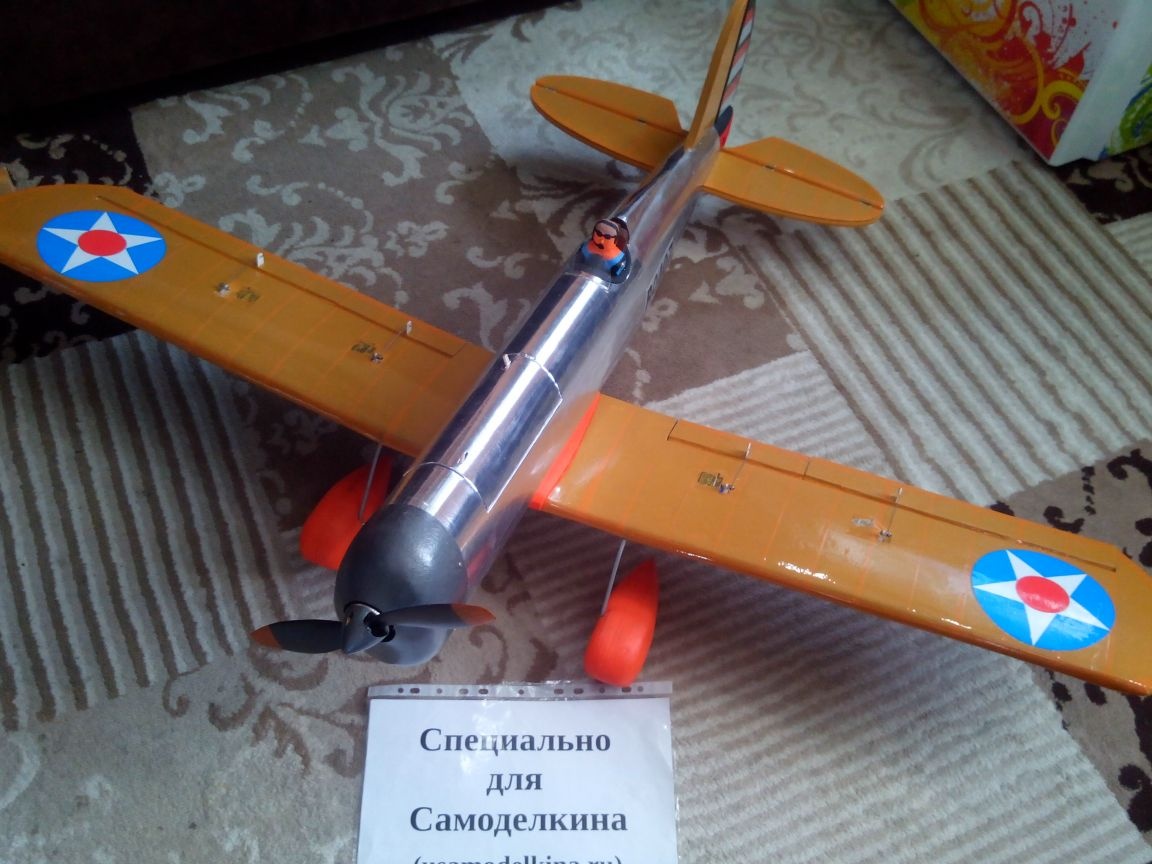
This article describes in detail the manufacturing process of a model of an American aircraft. Ryan STA Special Super 200 from depron, ceilings, bamboo sticks and wooden rulers. It may seem that this model the complexity of manufacturing is more suitable for experienced modelers, but in reality it will not be much more difficult to manufacture any other coach from the ceiling. It can only take a little longer. Well, it might be a pity to break it, but it's better not to think about it.
Materials:
- Ceiling tile
- Depron (substrate under the laminate)
- Penoplex
- Plywood 3 mm
- Wooden rulers
- Bamboo sticks
- Scotch multi-colored
- patch
- Steel wire and rods
- Spring ballpoint pens
- Threads
- Acrylic paints
- Bolts and nuts (M3 thread)
Instruments:
- Cutter
- Jigsaw
- scissors
- marker
- Ruler
- Square
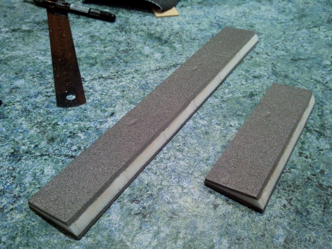
- Sandpaper
- Needle files
- Thermogun
- Dremel
- Drill and drill
- Glues (PVA, ceiling, epoxy)
- Thin tube
- Iron
- pins
Electronics (links lead to Parkflyer store)
- A motor - or another with a thrust greater than 1 kg
- Regulator - (depending on engine and battery)
- Servos - (6 pieces if you make flaps or 4 pieces if you do without them)
- Batteries - or analogues
- Propellers - or analogues
- Kok -
- Extension cords -
- Rod locks -
- Equipment - or any other on 5 or more channels
Step 1. Drawing and templates
Drawing
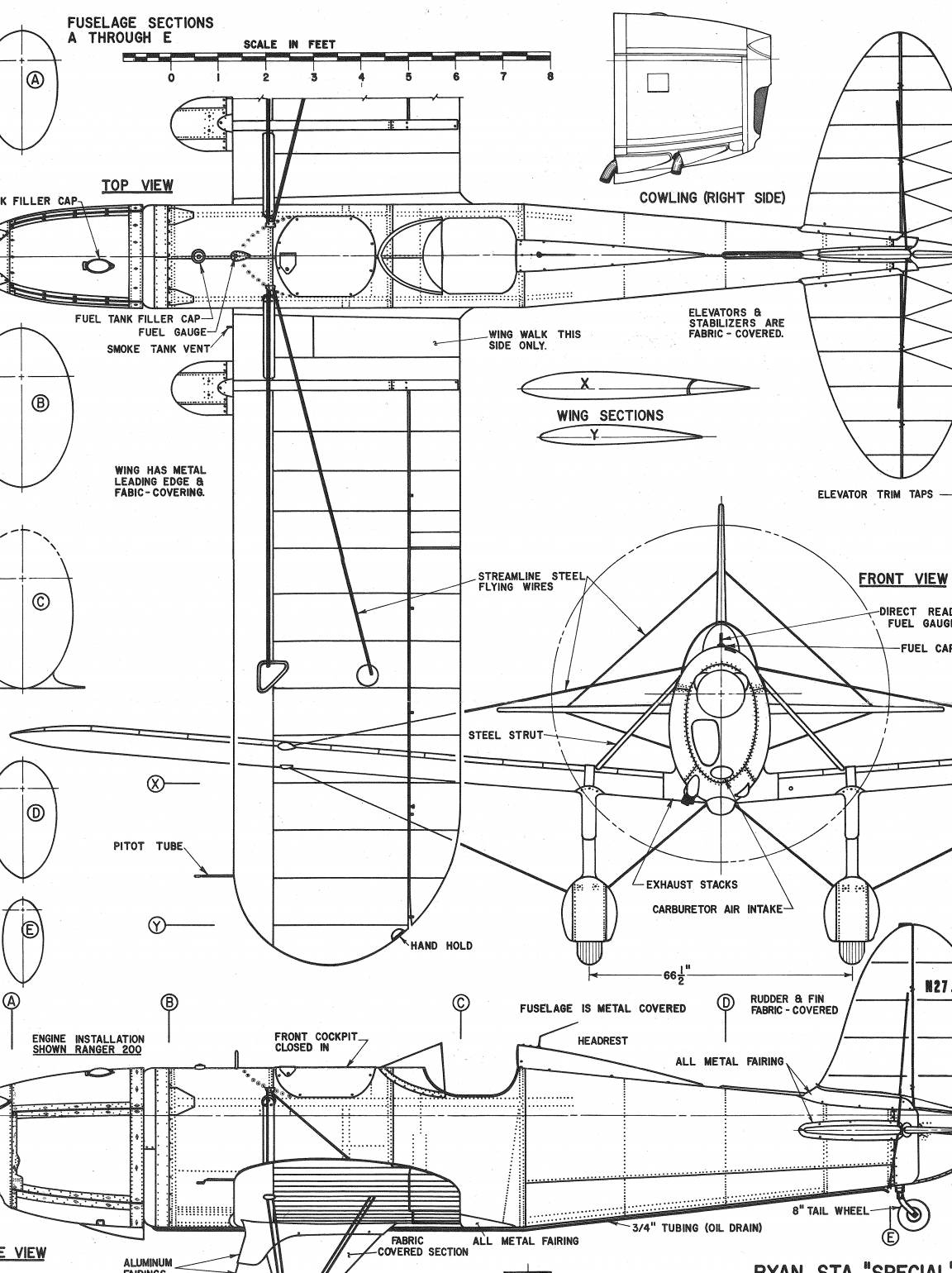
Drawing of a model in PNG format in three projections. On it with the help of a ruler, a calculator and a simple proportion, you can prepare templates for any size. I decided to stay on a model with a wingspan of 1300 mm.

Since he did not strive for perfect copying, he immediately decided to remove some details (for example, numerous stretch marks) and simplify the shape of the fuselage.
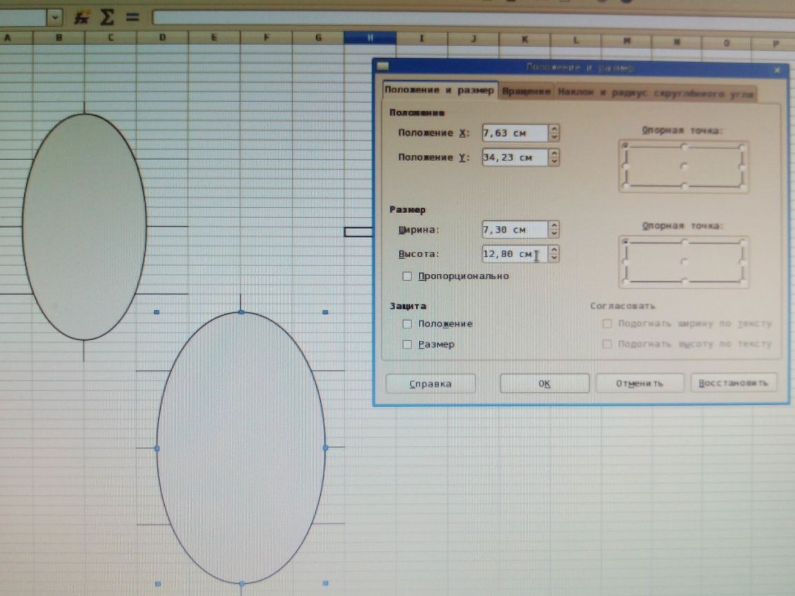
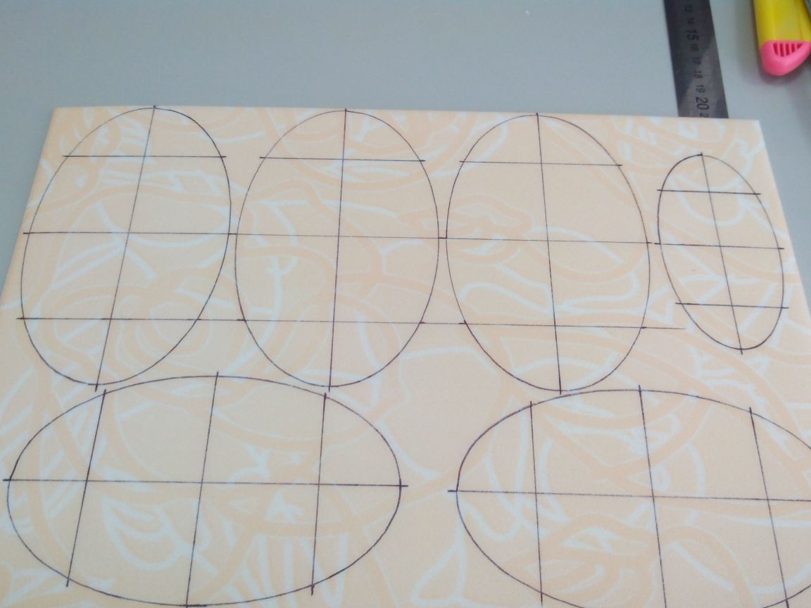
As a result, the frame templates are made in Excel, these are ellipses with the given sizes.
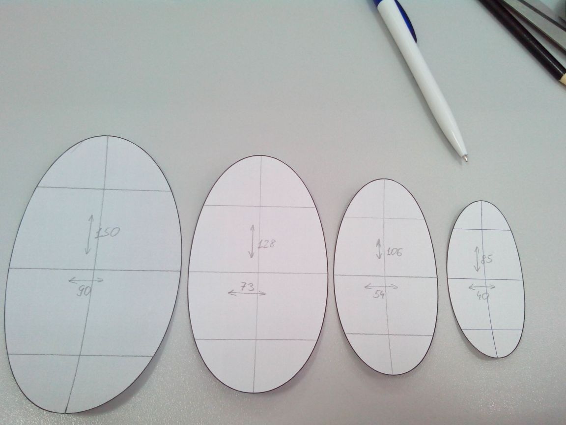
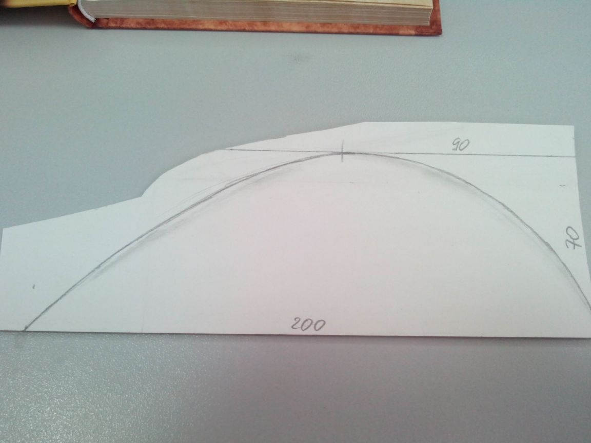
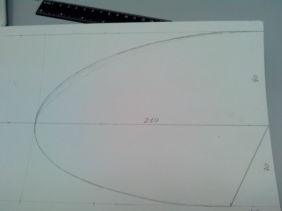
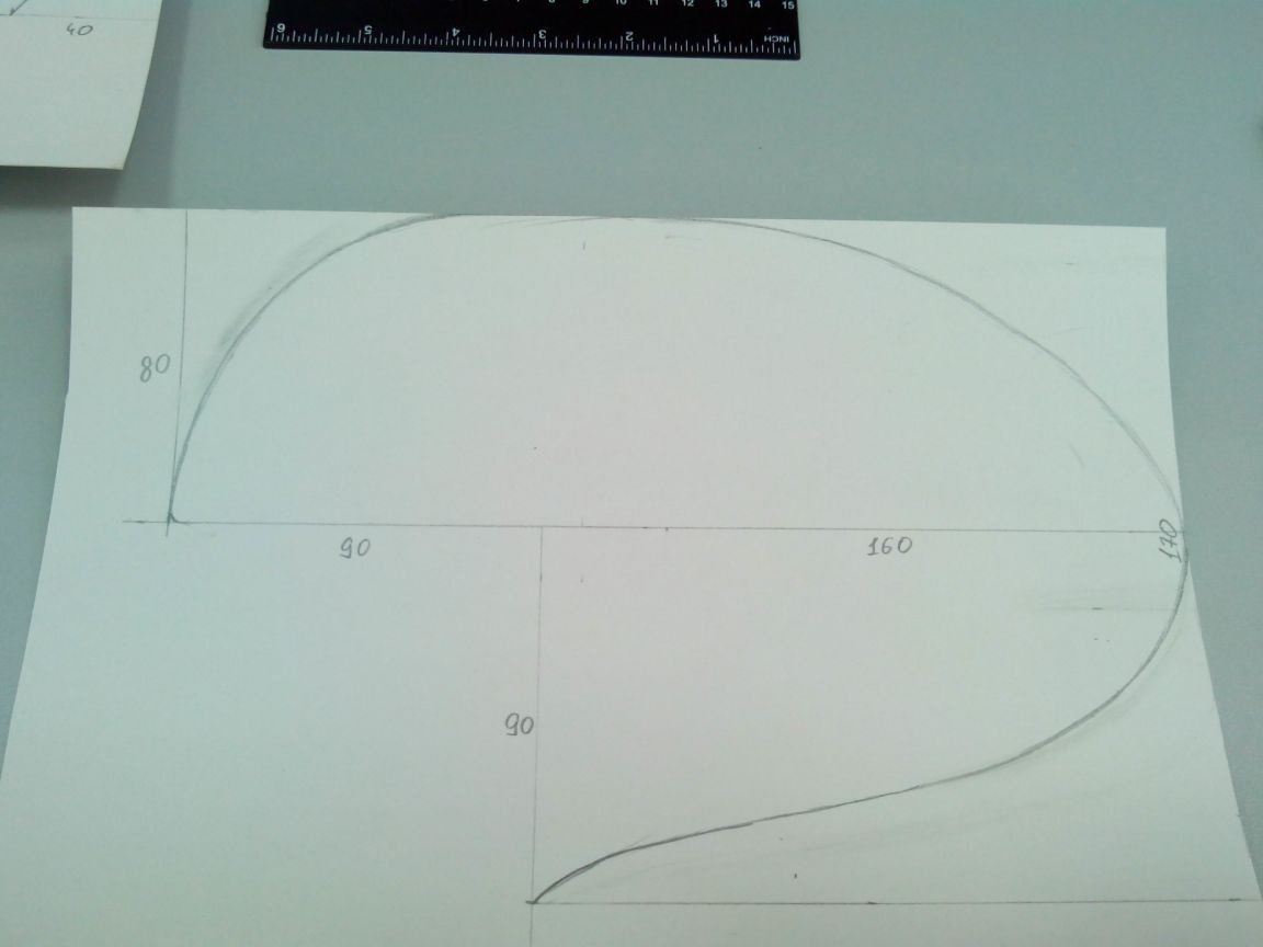
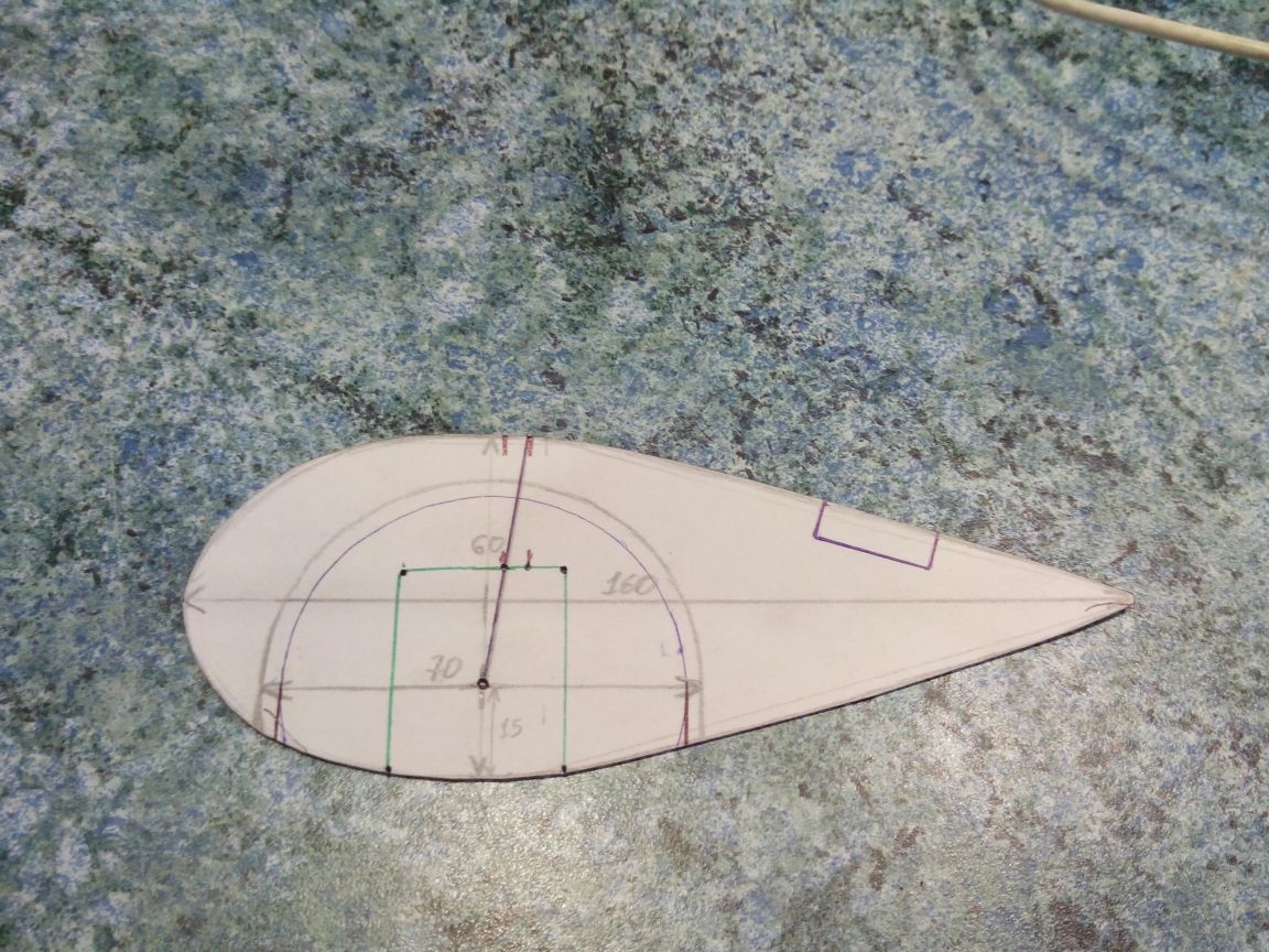
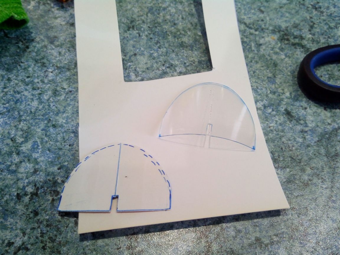
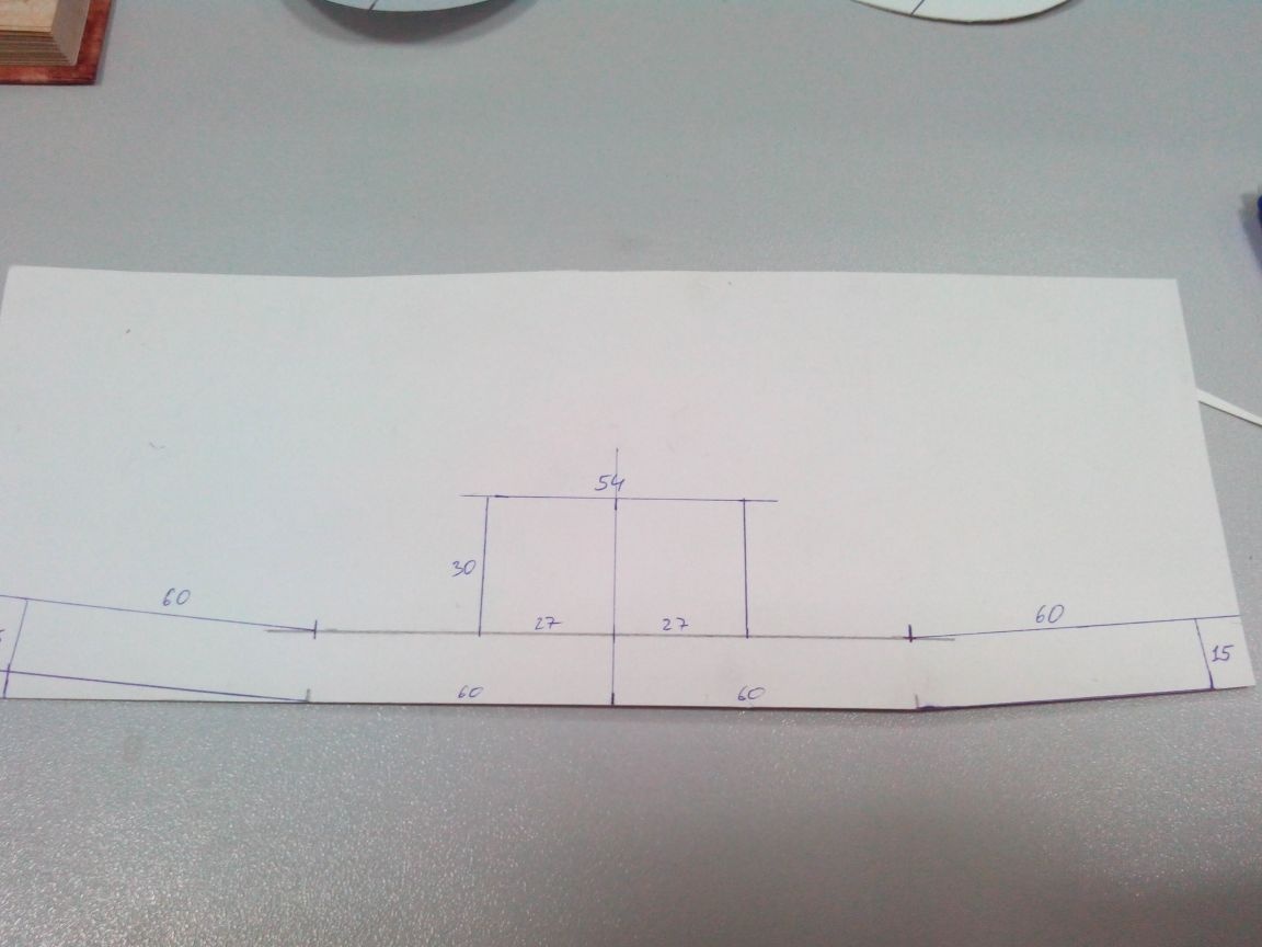
Patterns of wingtips, stabilizer, keel, rudders and fairings of wheels painted directly on whatman paper. Dimensions can be seen in the photo.
Step 2. Making the fuselage
This step can be conditionally divided into two parts: before the manufacture of the wing and tail, and after. But I decided to place the whole process in one step.
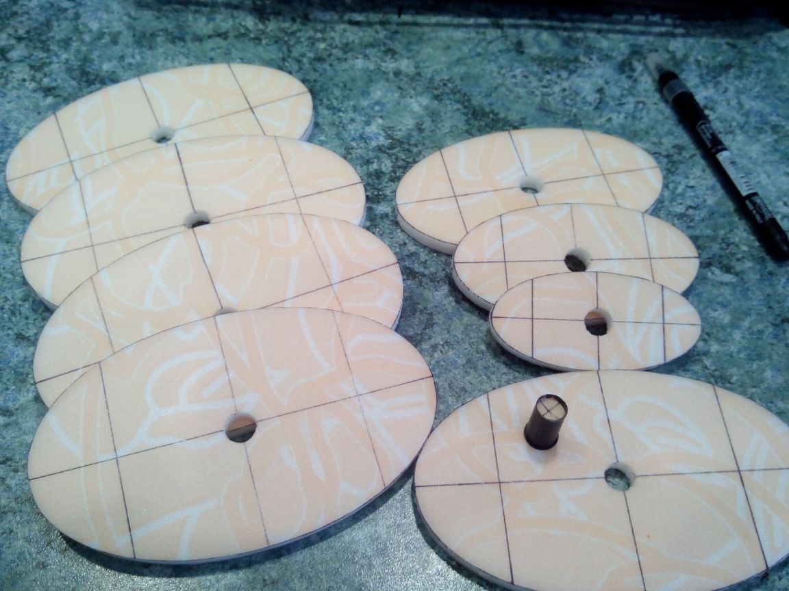
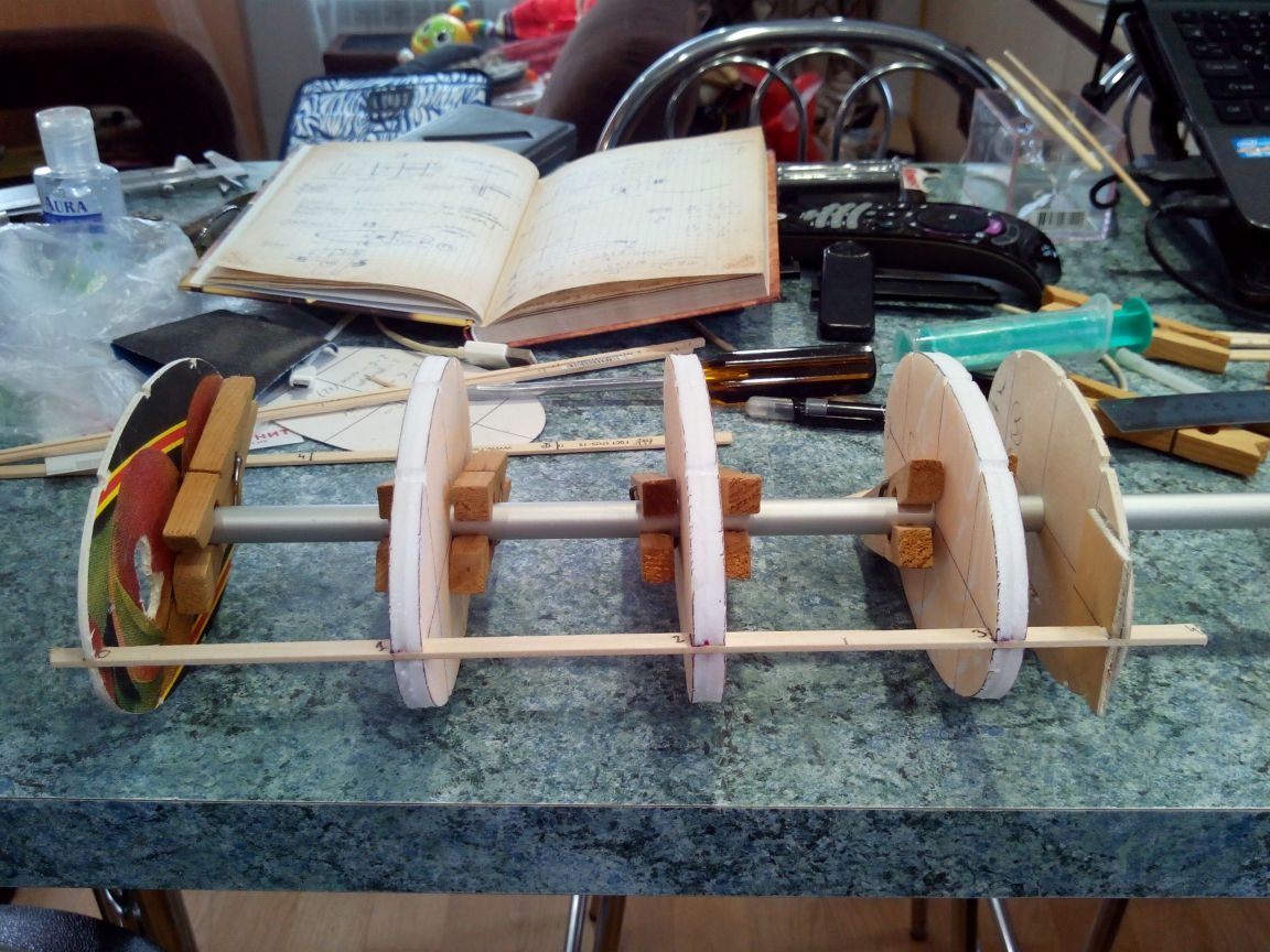
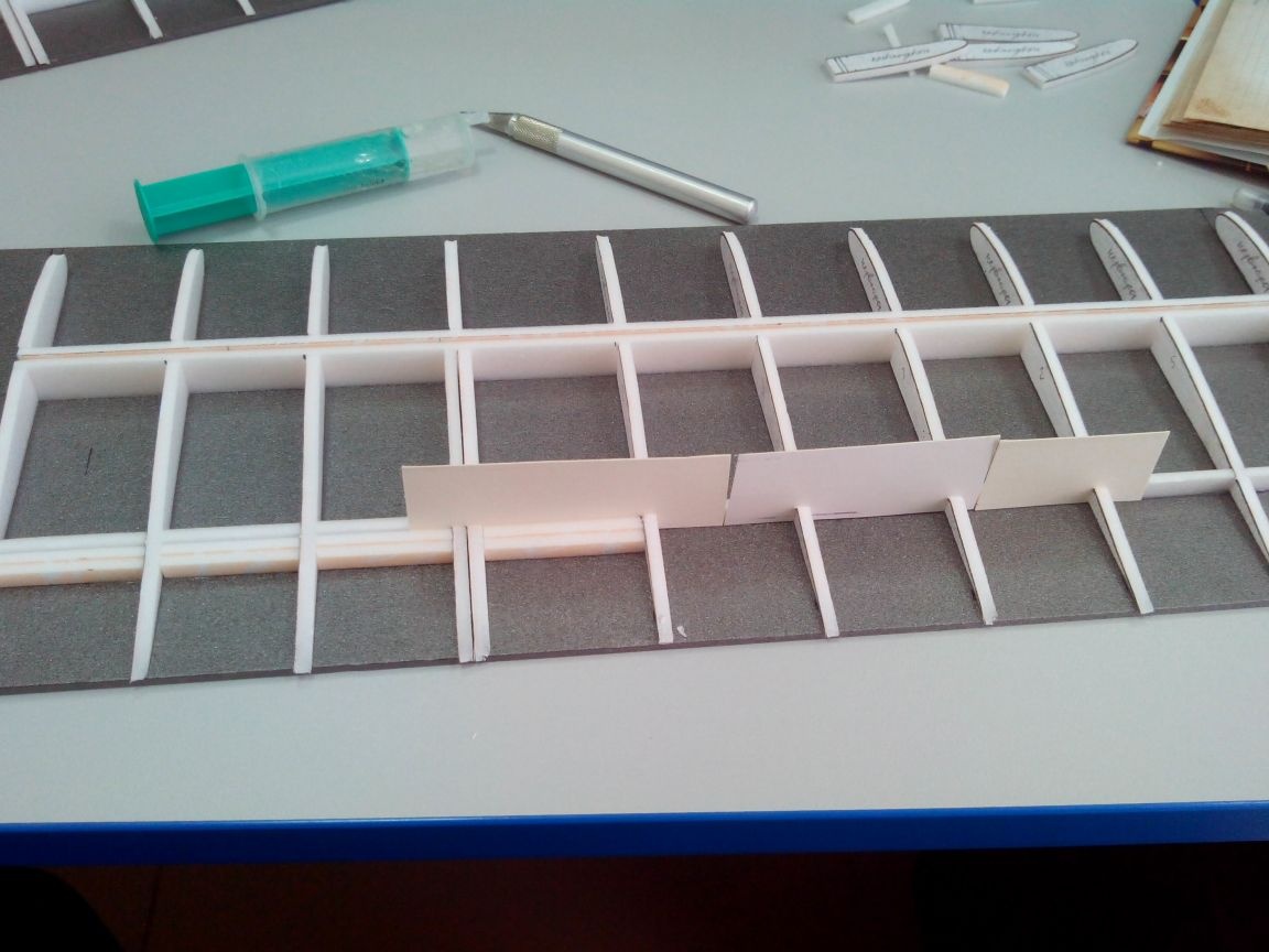
So, we draw frames on the sheet of the ceiling according to the templates.
We cut and glue them in pairs to make frames of the double layer of the ceiling and make holes in the center for the slipway tube.
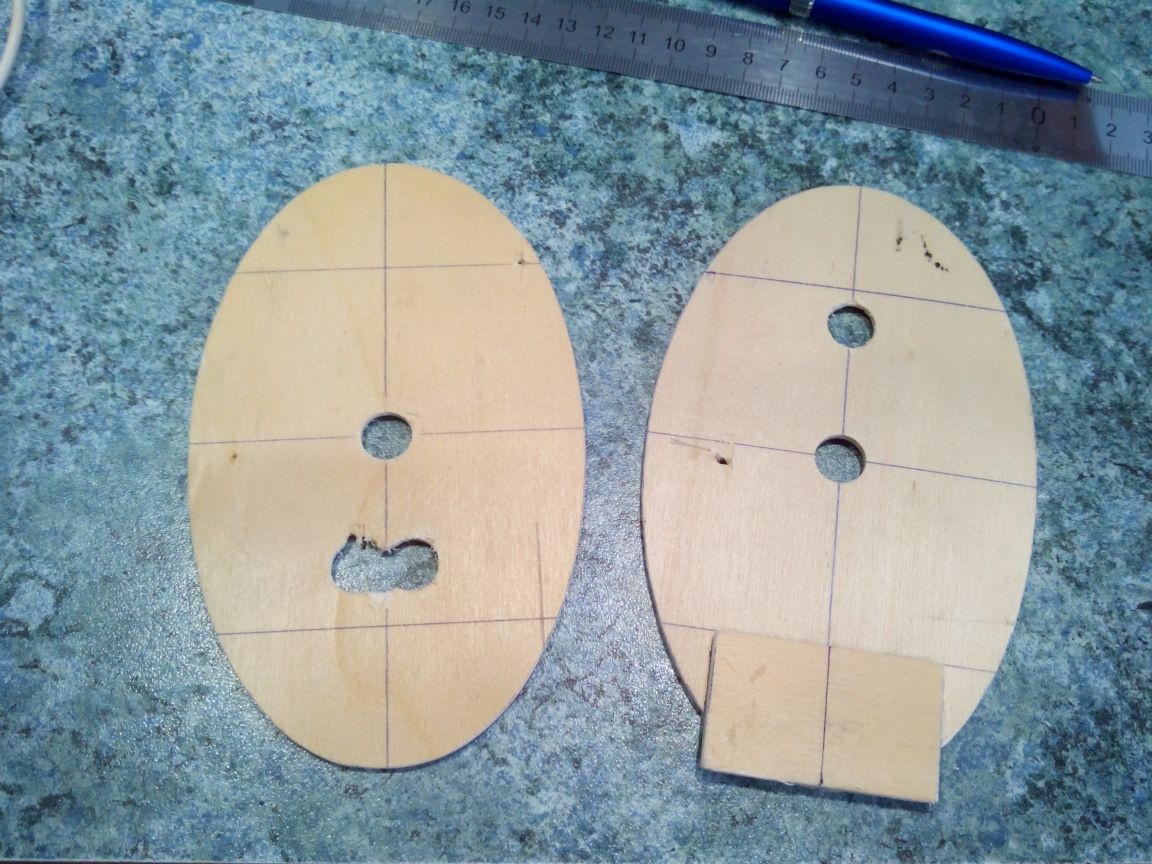
From 3 mm plywood, cut out the 0 and 4 frames with a jigsaw. At zero, the motor will be fixed, at the fourth - the wing. To the fourth frame we glue on the PVA a rectangular pad-thickening. In addition, we drill additional holes for wires.
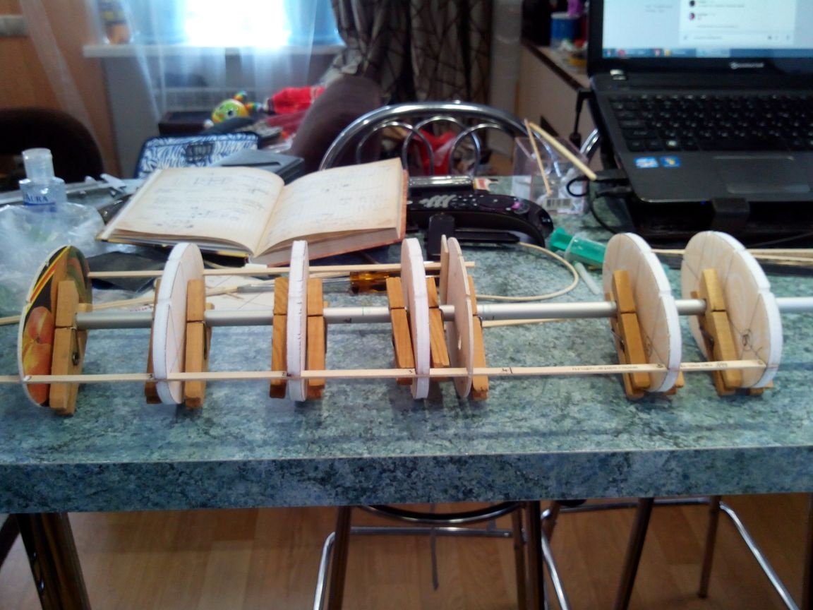
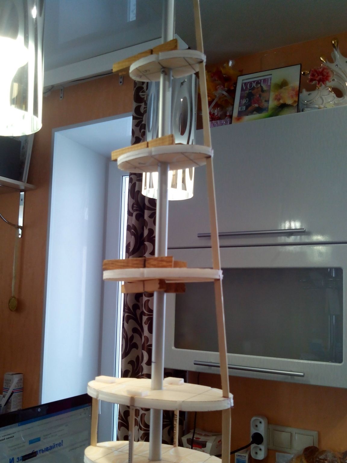
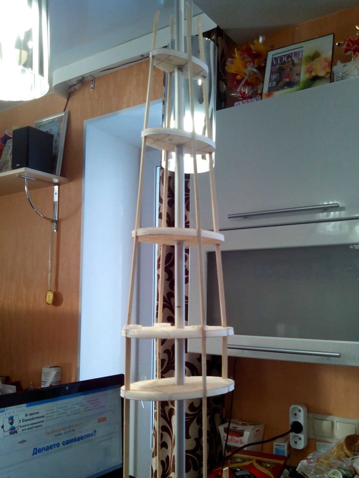
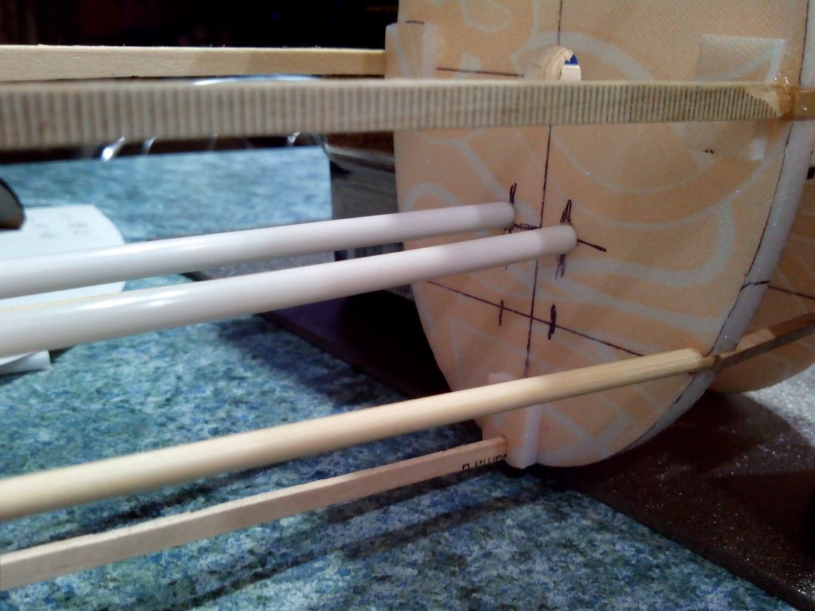
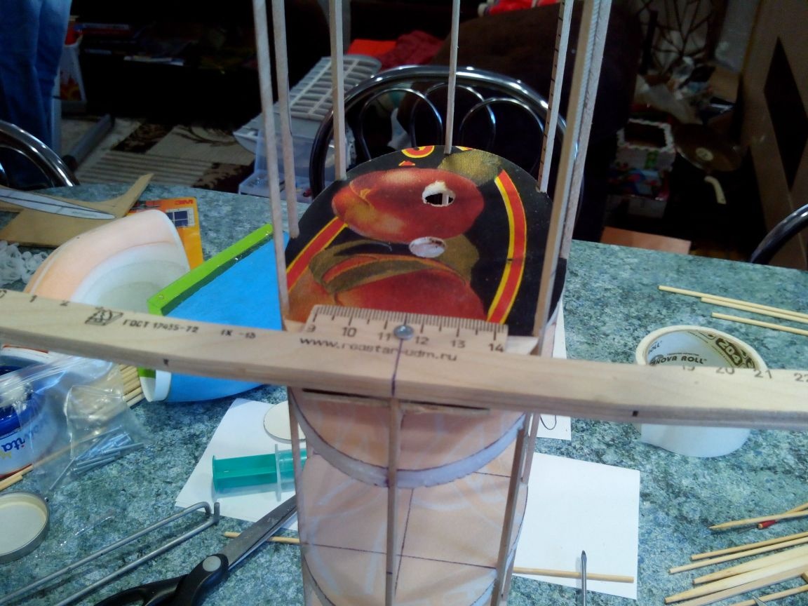
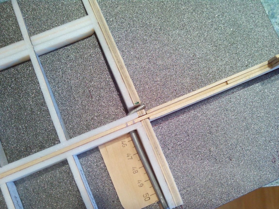
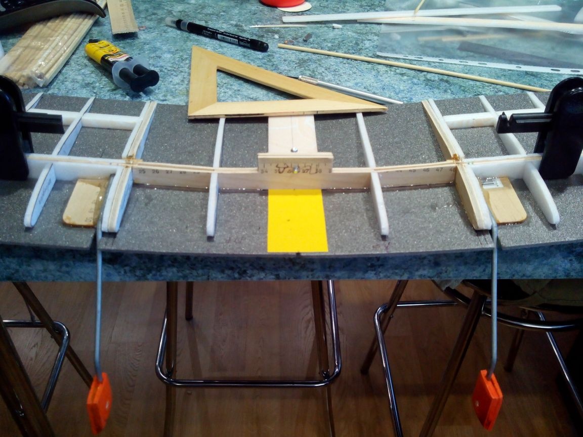
We put the frames in order on the slipway tube. We make holes with a pen drill in plywood and a tube from threads in foam.
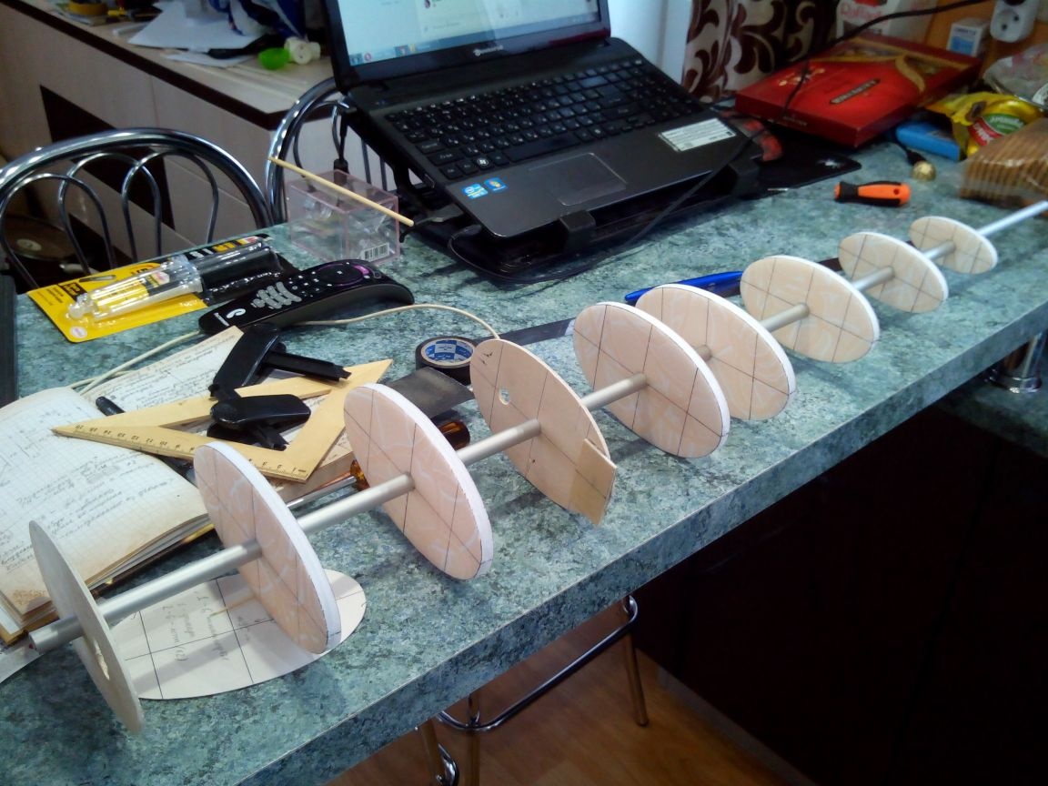
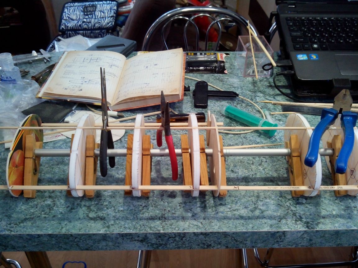
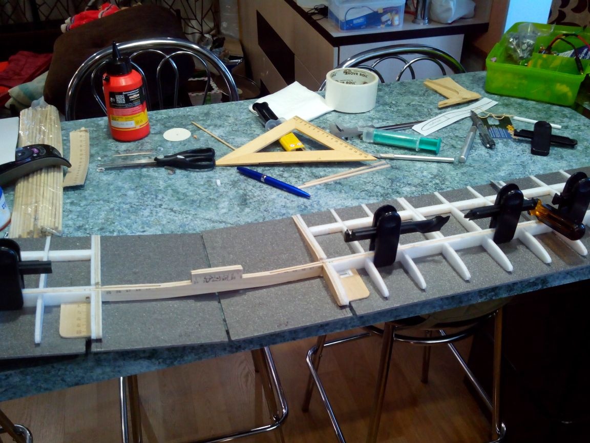
We fix the frames on the tube with clothespins and start gluing stringers from rulers and bamboo sticks. In plywood frames, cutouts for stringers are made with a jigsaw, and in ceiling - with a file.
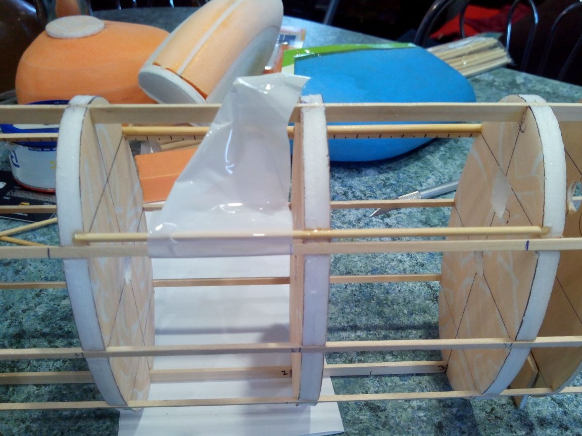
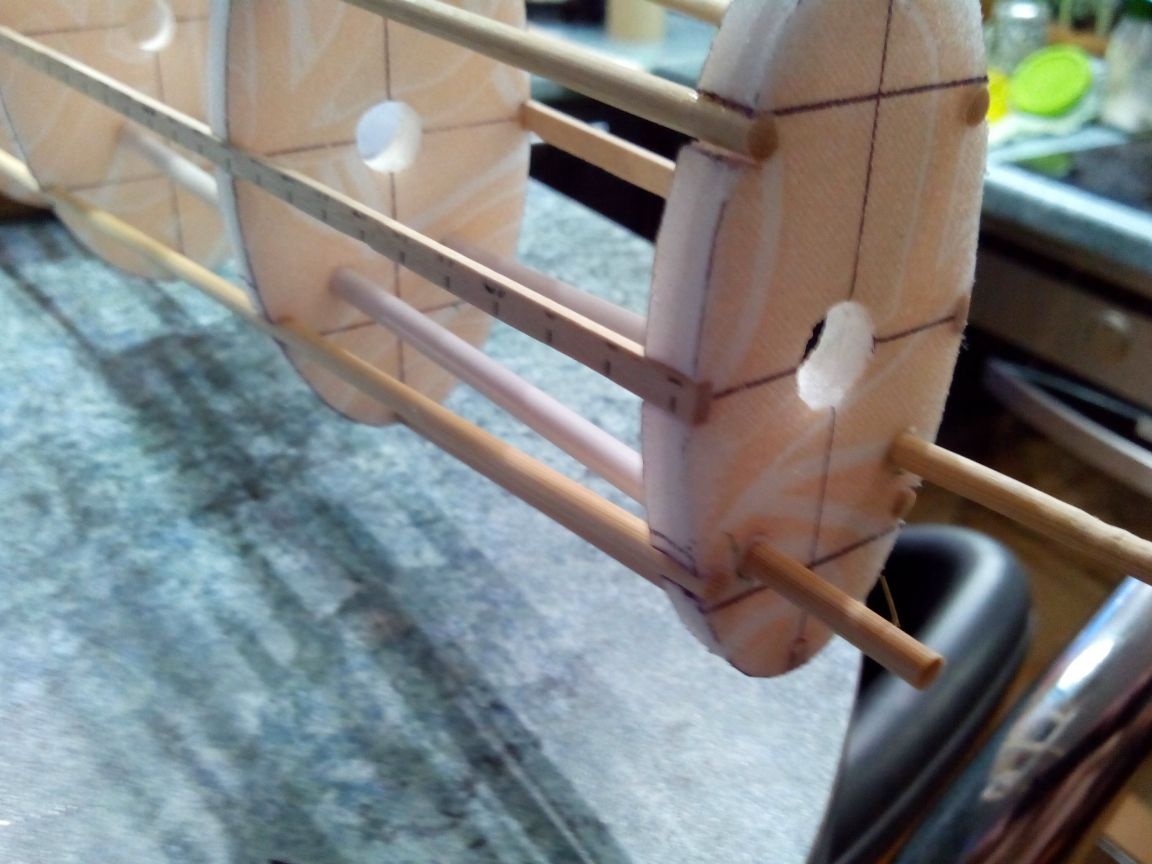
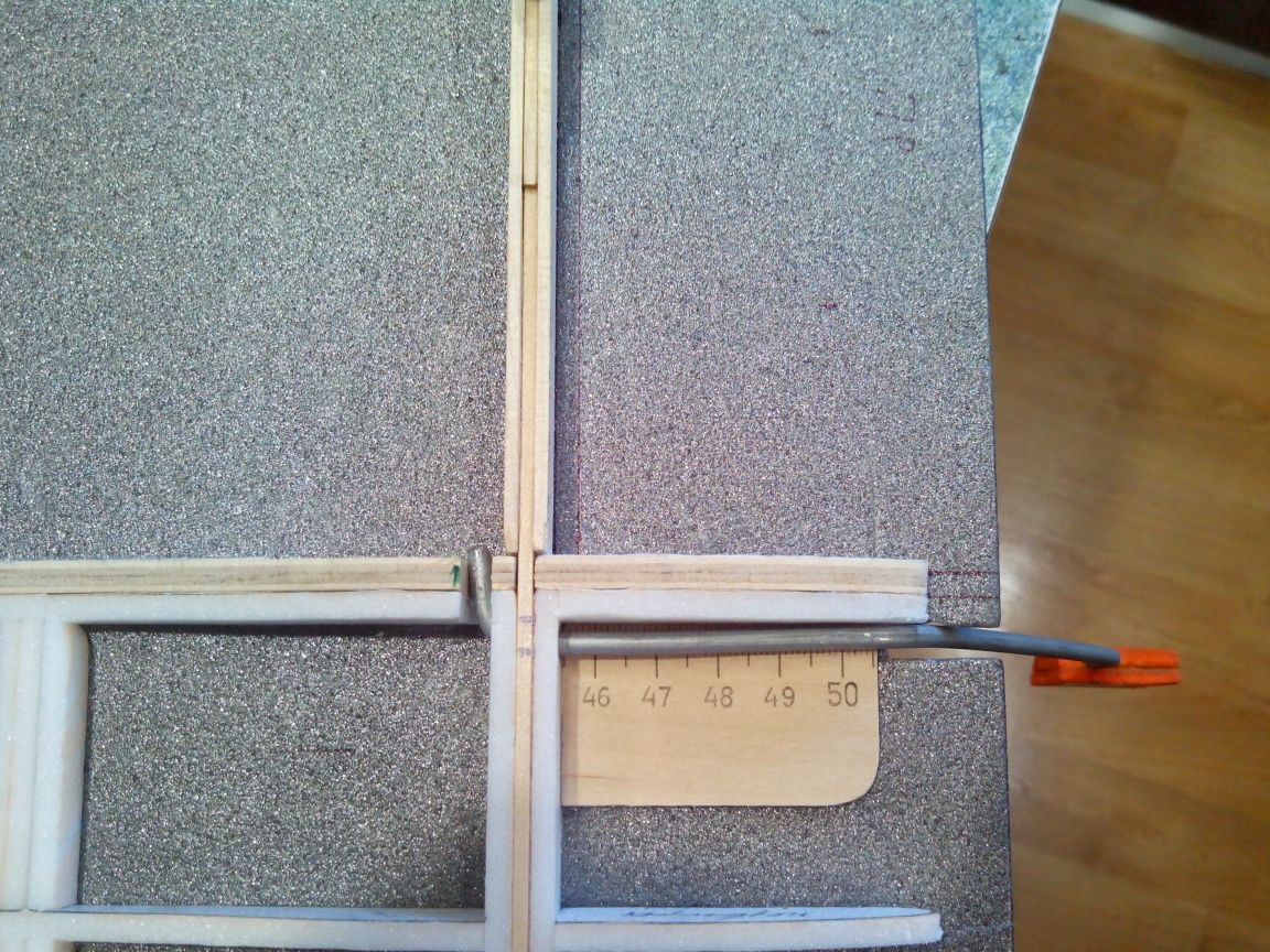
Glue the upper stringer.
We glue the side stringers.
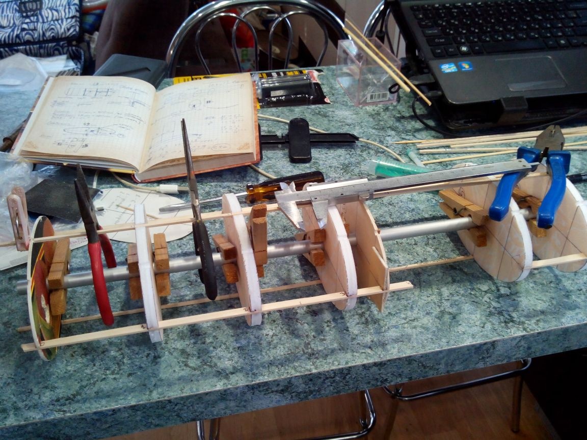
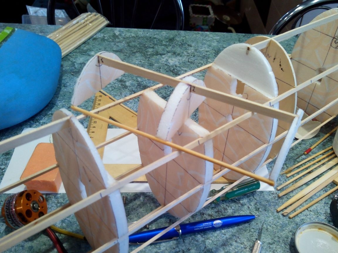
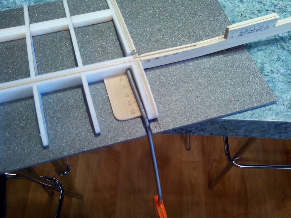
We pass to the tail.
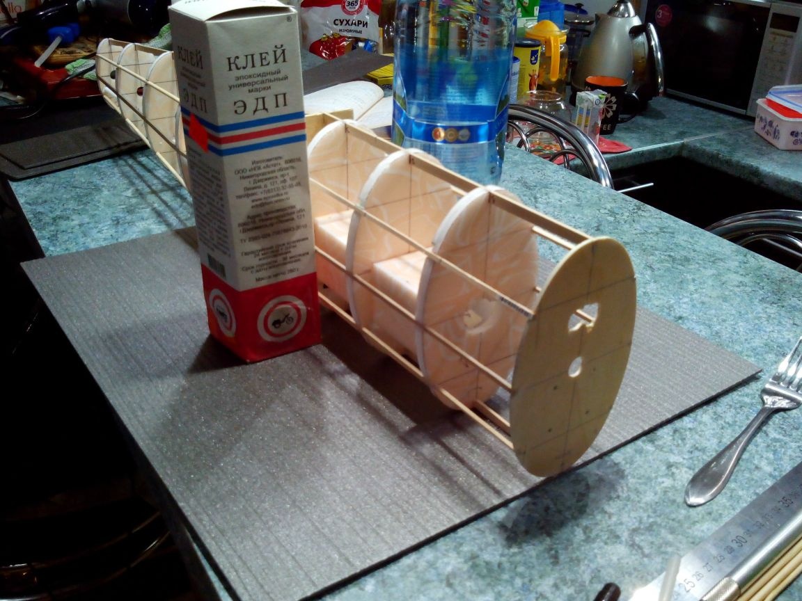
After all the stringers are glued and the glue has dried, we proceed to the manufacture of the engine compartment.
To do this, we glue additional stringers between the 1st and 3rd frames 2 mm higher than the main stringers. In addition, these stringers to the 1st and 3rd frames must be glued to half the width.
Using a jigsaw, carefully cut out the frame of the future cover.
From the ceiling tiles we make a box-motor compartment, cut a rectangle from the 2nd frame and paste this box there. We insert the frame of the cover and temporarily fix it with pieces of electrical tape.
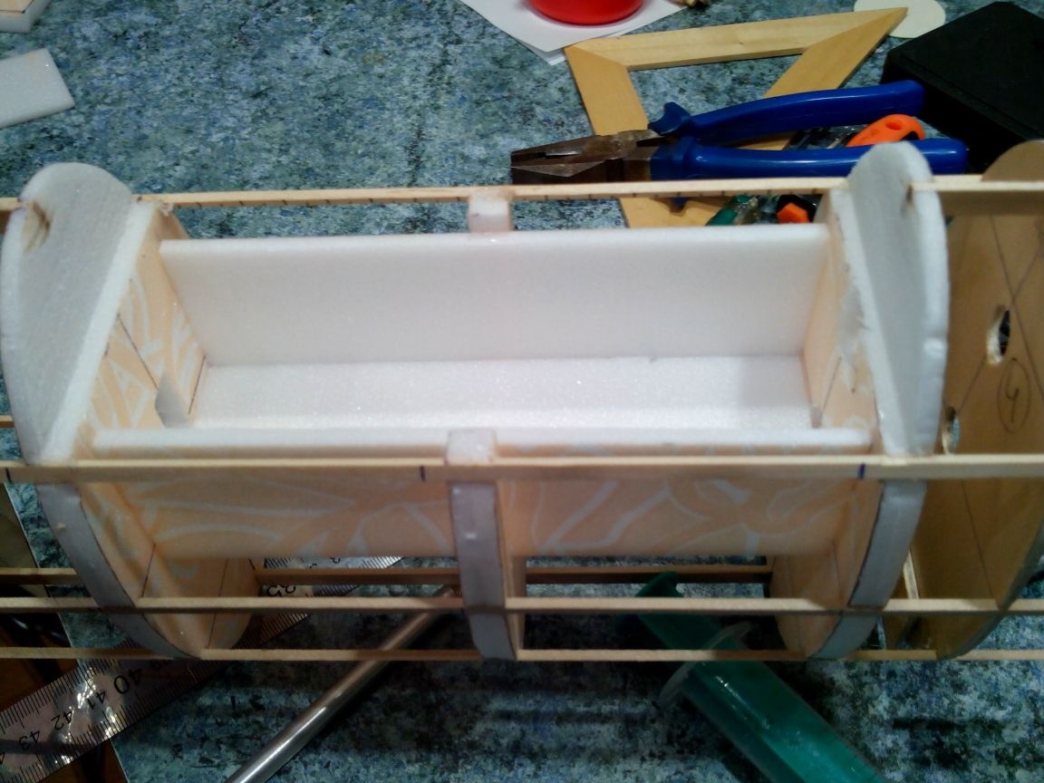
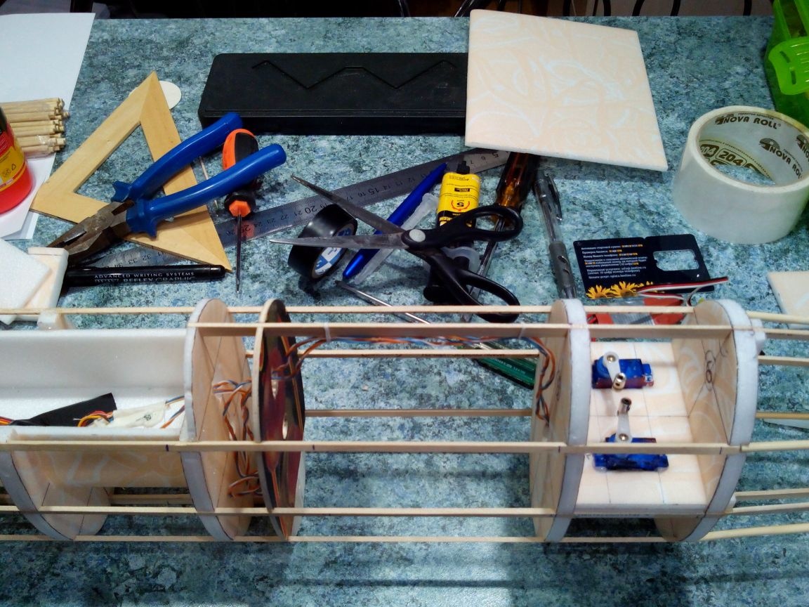
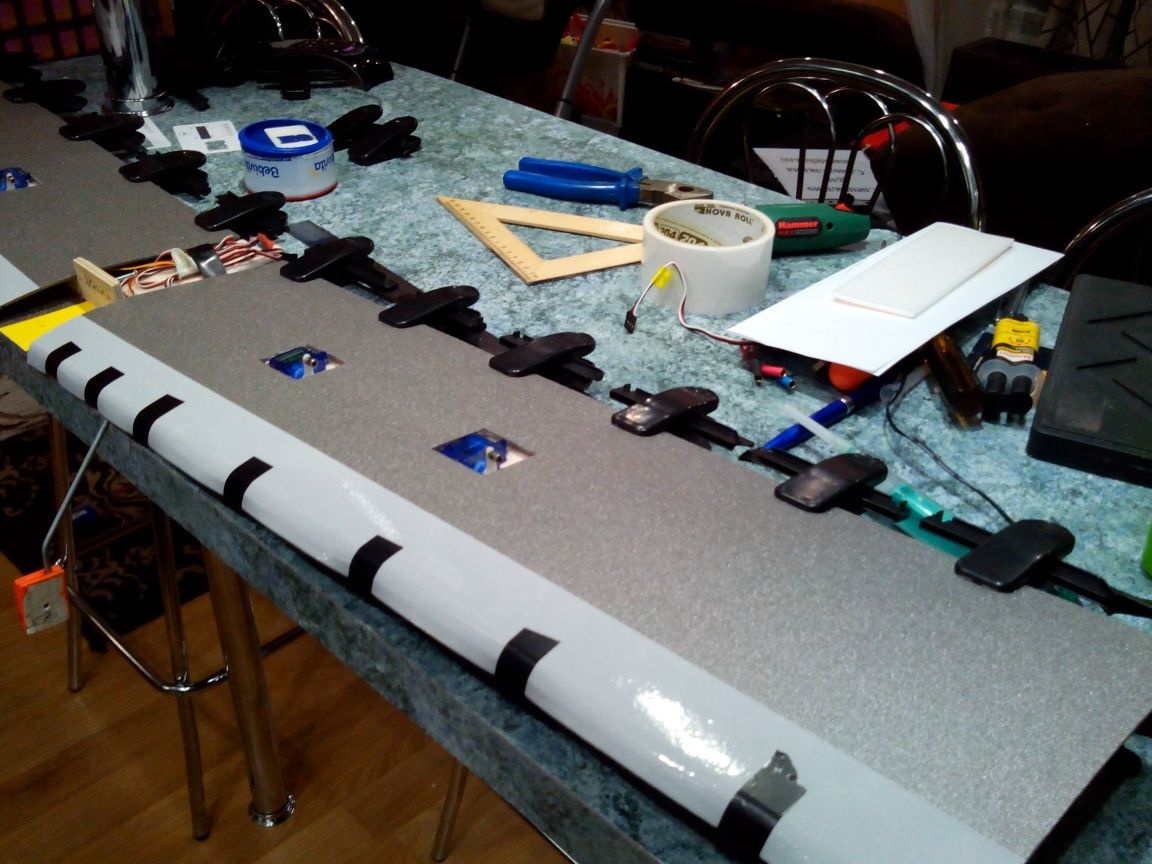
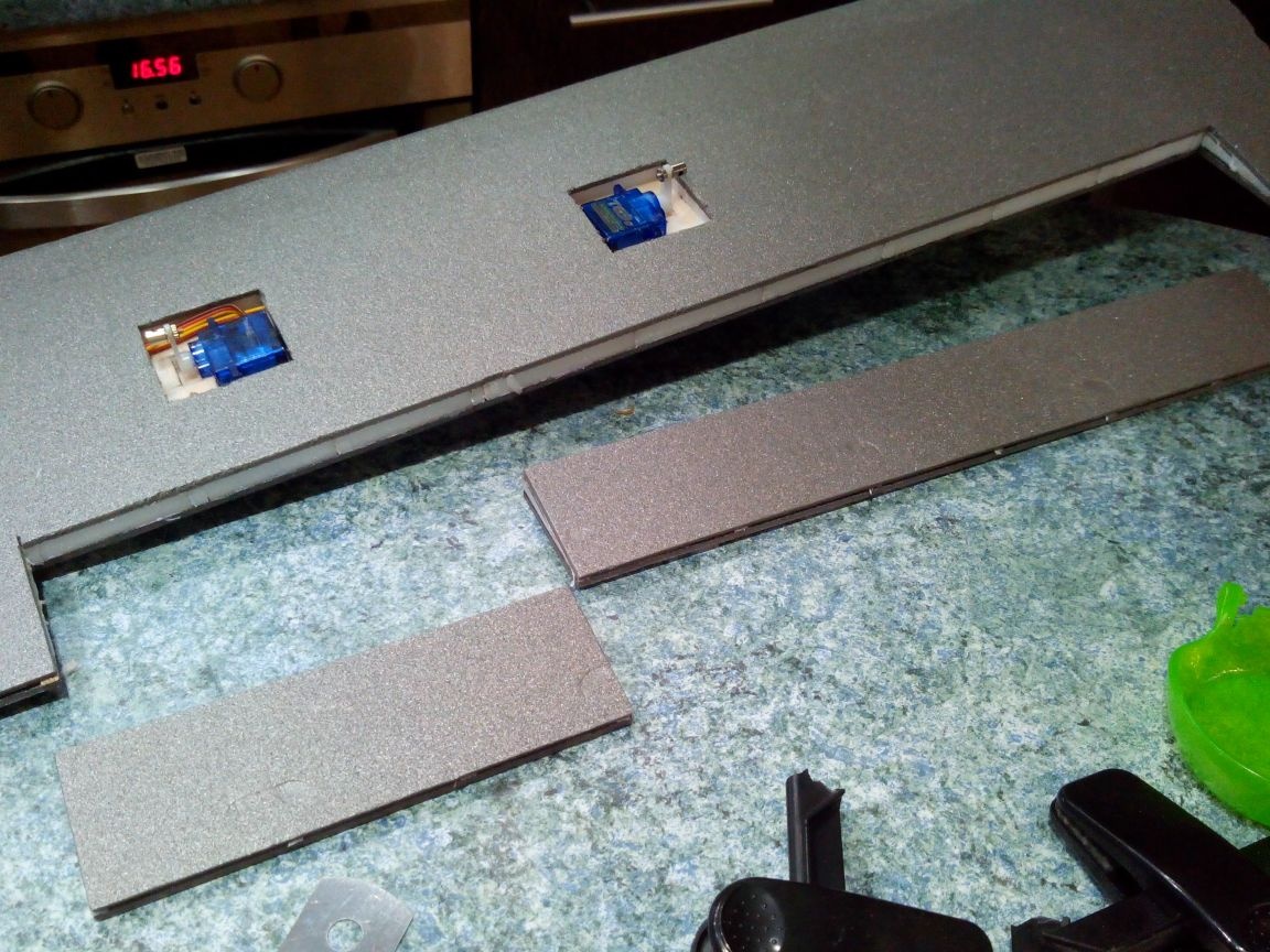
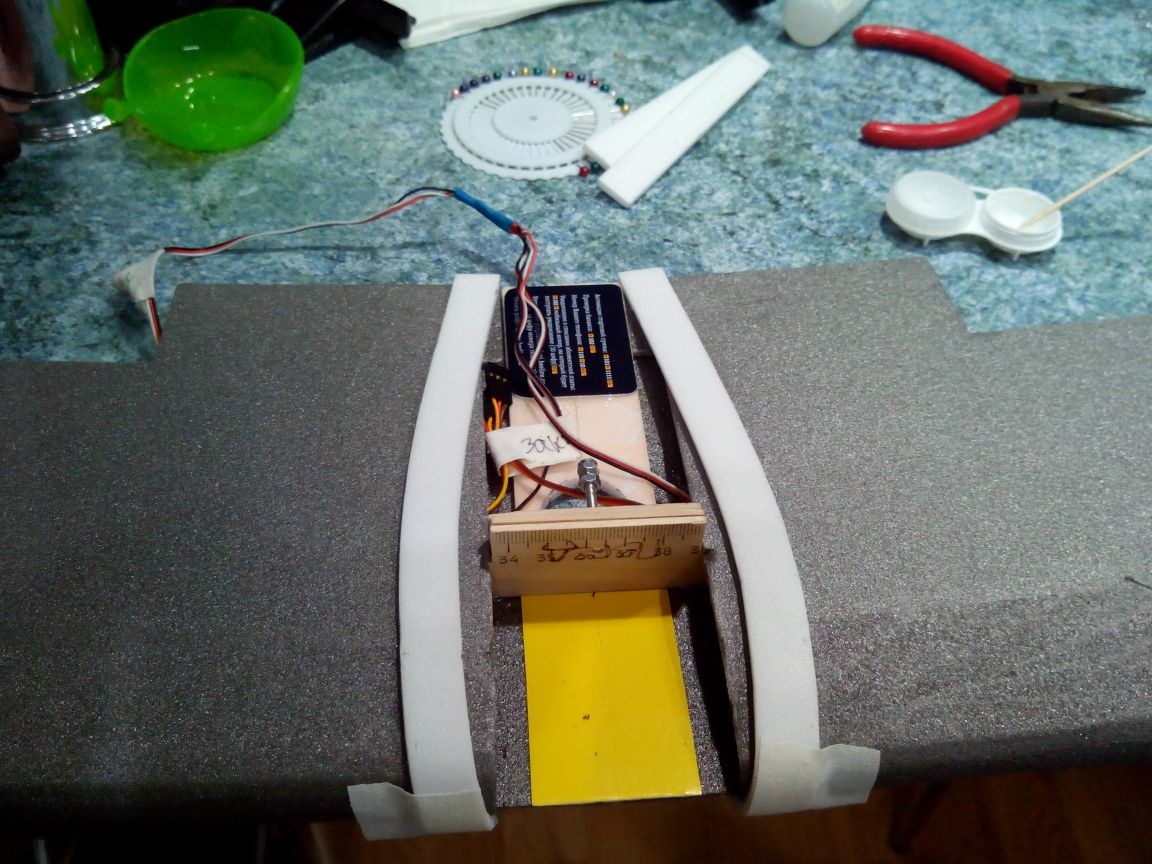
From the double layer of the ceiling we cut out the platform for the tail servos and glue between the 5th and 6th frames. Servo drives can be glued at this step - it is more convenient to stretch the wires to the engine compartment. But it is better to fix the wires in the motor compartment with electrical tape.
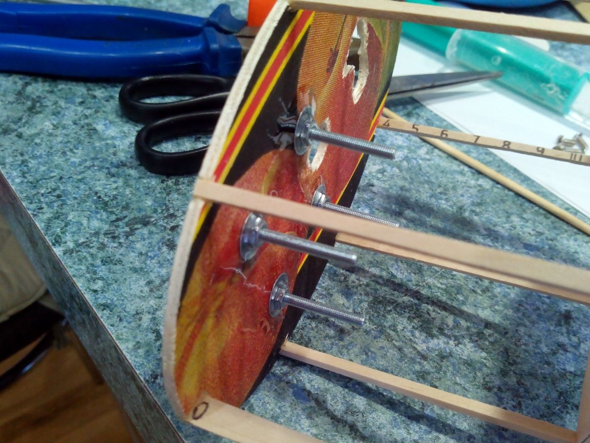
We fasten bolts with nuts to the 0-th frame of the engine mounting cross.
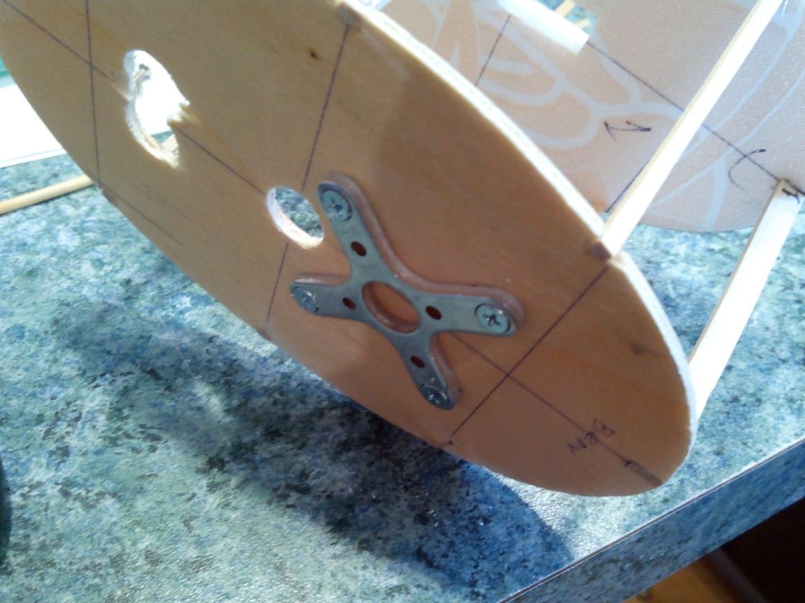
And fill the nuts with an epoxy five-minute.
We also paste epoxy on the tail end of the bowden from the balloons.
In order not to suffer with knitting needles and hooks later, I recommend extending the Y-cables and extension cords from the place of the wing attachment to the motor compartment before covering the fuselage.
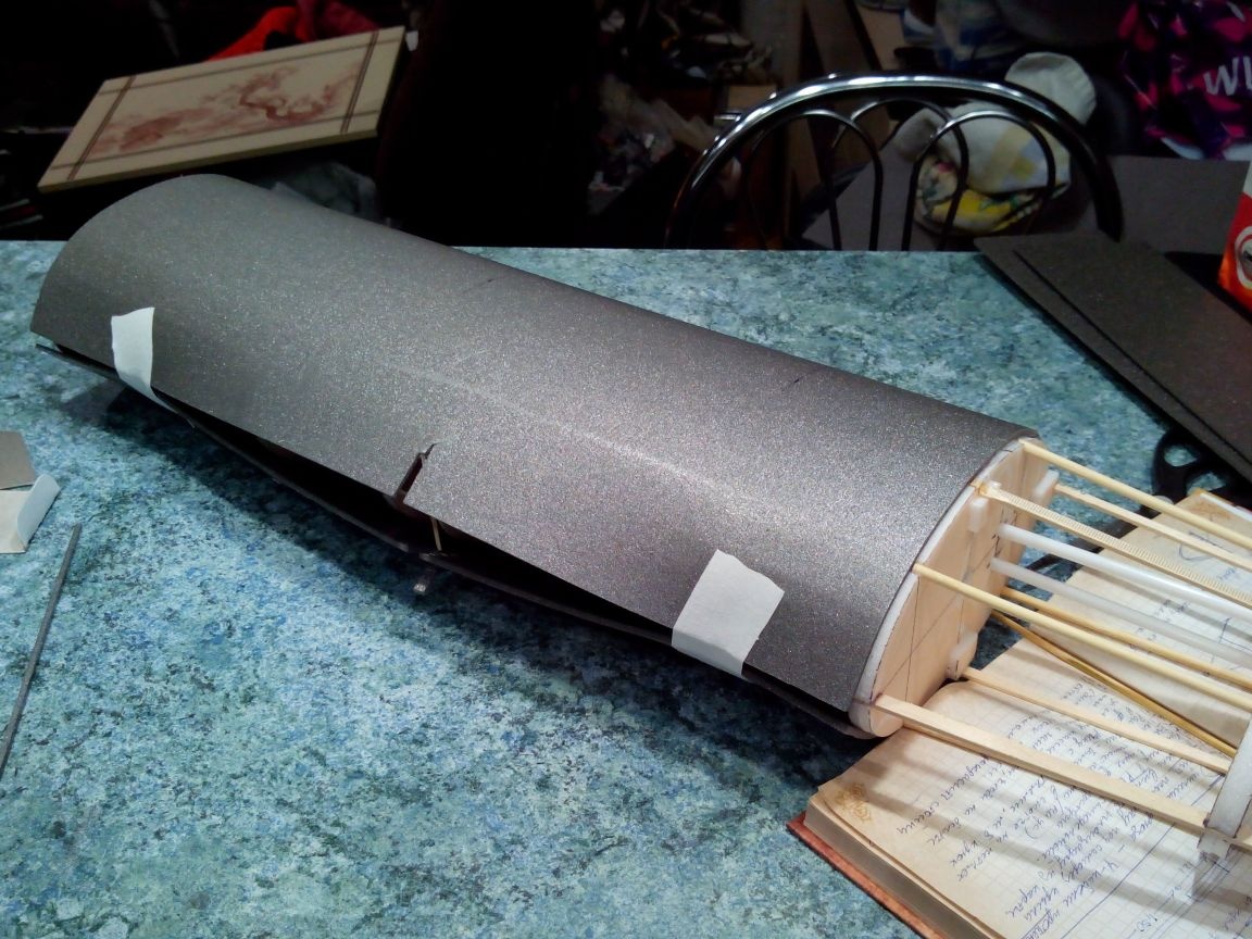
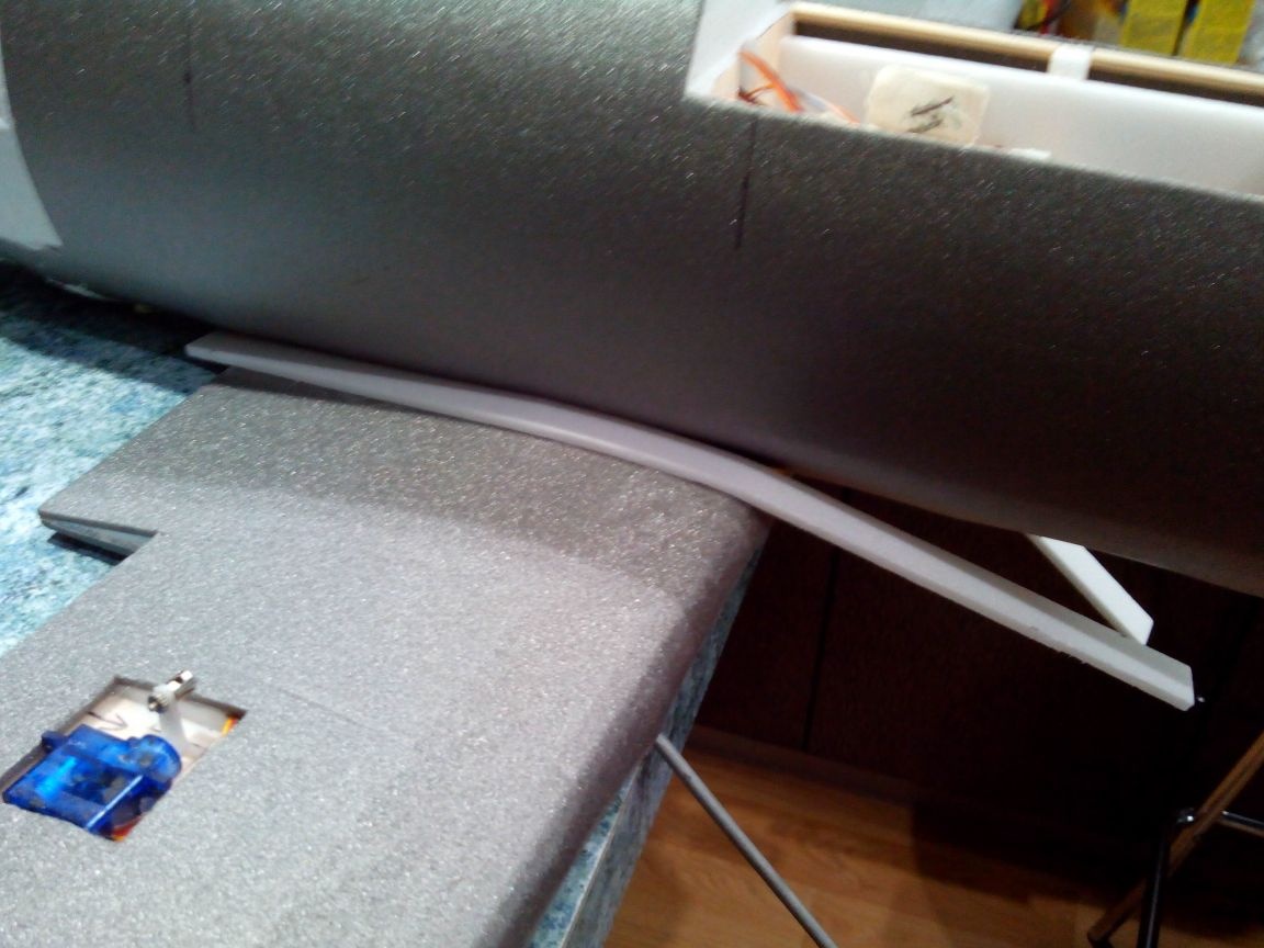
Everything, the fuselage frame is ready, you can proceed with the deprot sheathing. It is easier to do this in two stages, first sheathing the front part (before narrowing) and the tail (tapering).
To do this, we take a sheet of depron and on the reverse side along the entire sheet we press the lines with a table fork. Then we smear the upper stringer from the 0th to the 6th frames, including the motor compartment cover, with ceiling glue, glue it to the depressor and leave it to dry completely.
After the glue dries, we make through cuts in the region of the edges of the lid, so that later it is easier to find the lid, or measure with a ruler.
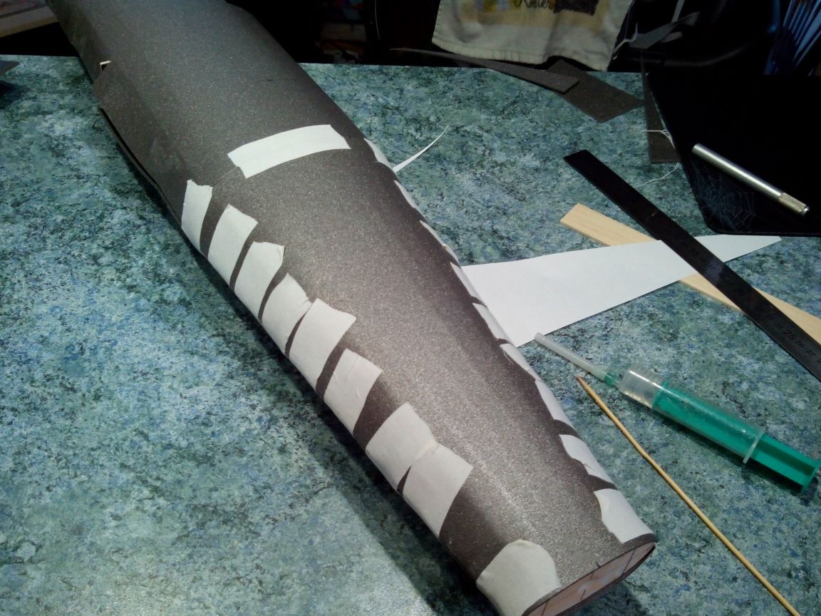
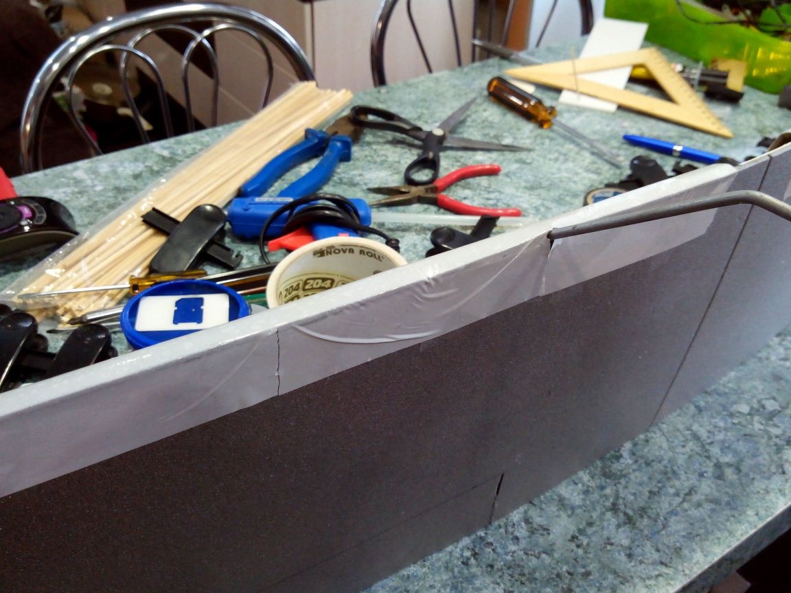
Then we smear all the frames and stringers with glue and gently begin to bend the depron. If everything is done carefully and without rushing, the skin will not break. The ends of the casing are fixed with a plaster or electrical tape.
It is more convenient to sheathe the tail part, having previously made a template from paper.
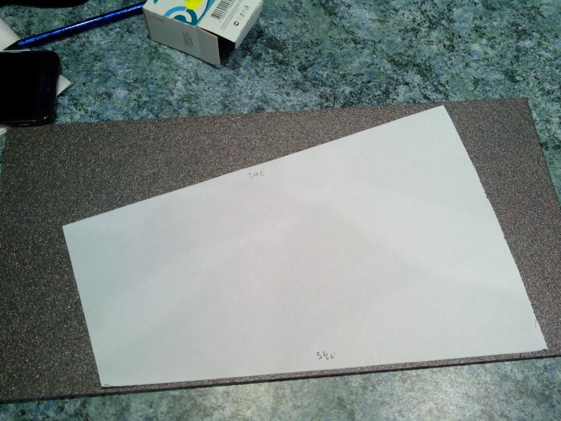
After cutting the halves of the tail trim, repeat the procedure with a fork and glue it, fixing everything with a band-aid.
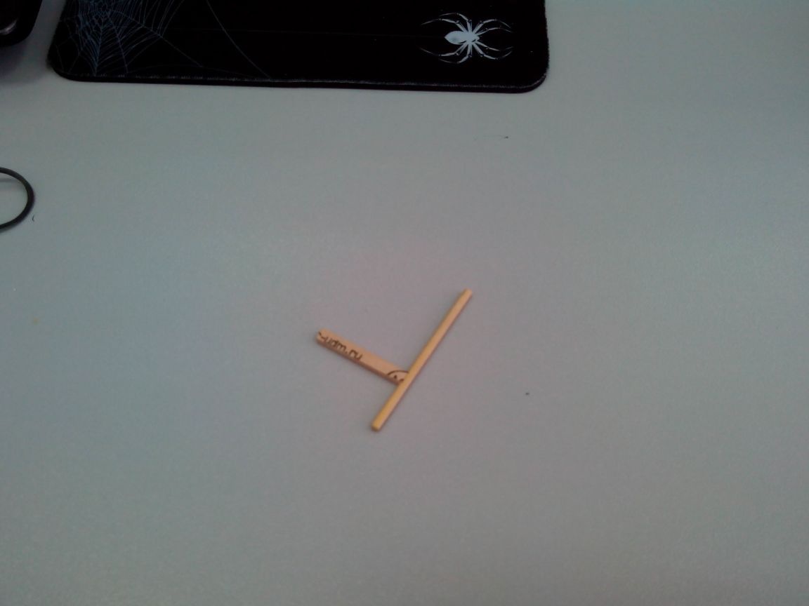
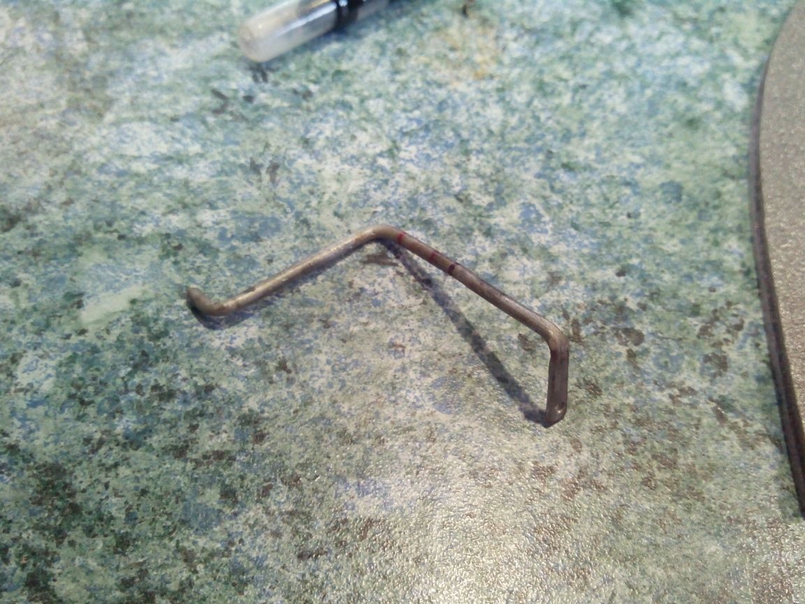
While the casing dries, we proceed to the manufacture of latches for the engine compartment cover.
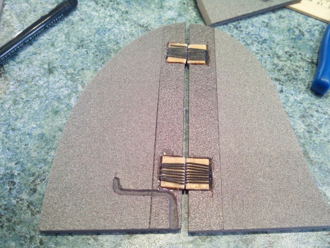
We cut out the details of the latch from a ruler and a bamboo stick and glue with PVA glue. We wrap the joint with threads on the glue.
Glue the frame of the latch.
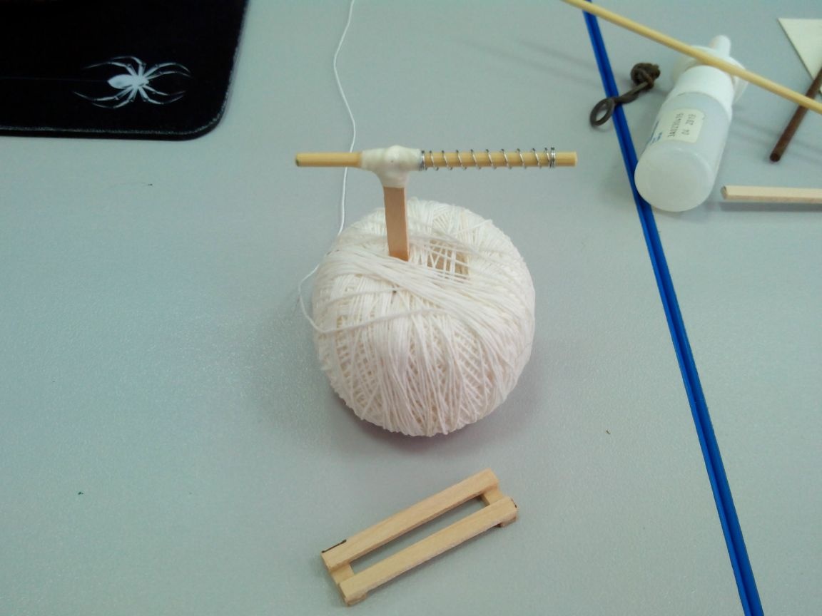
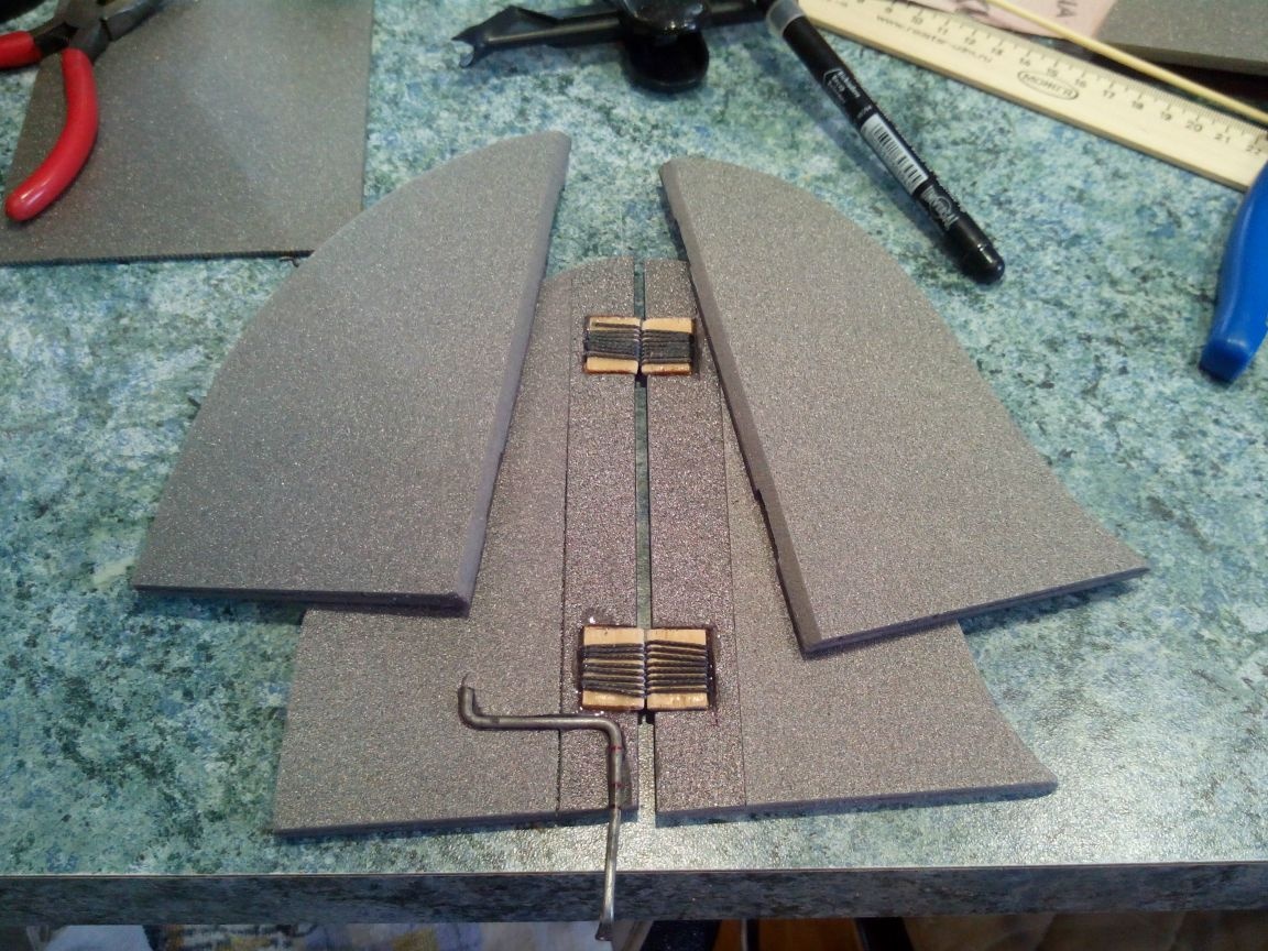
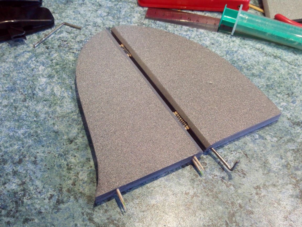
We put a spring on the latch, insert it into the frame and glue the last part of the frame.
Cut the motor compartment cover with a cutter, make two slots for the latches handles and glue the latches with hot melt adhesive.
The further idea should be done when the wing and tail are already made, but since all this relates to the fuselage, it will be considered at this step.
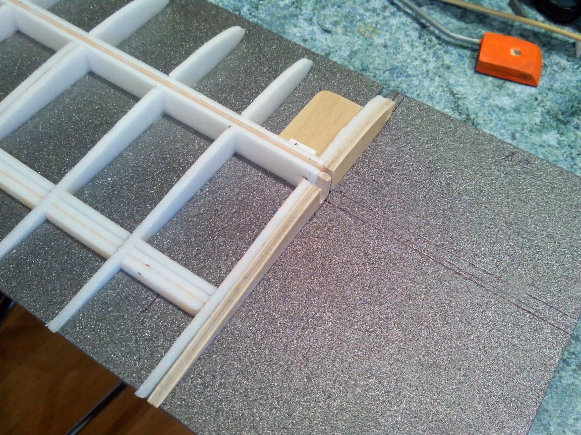
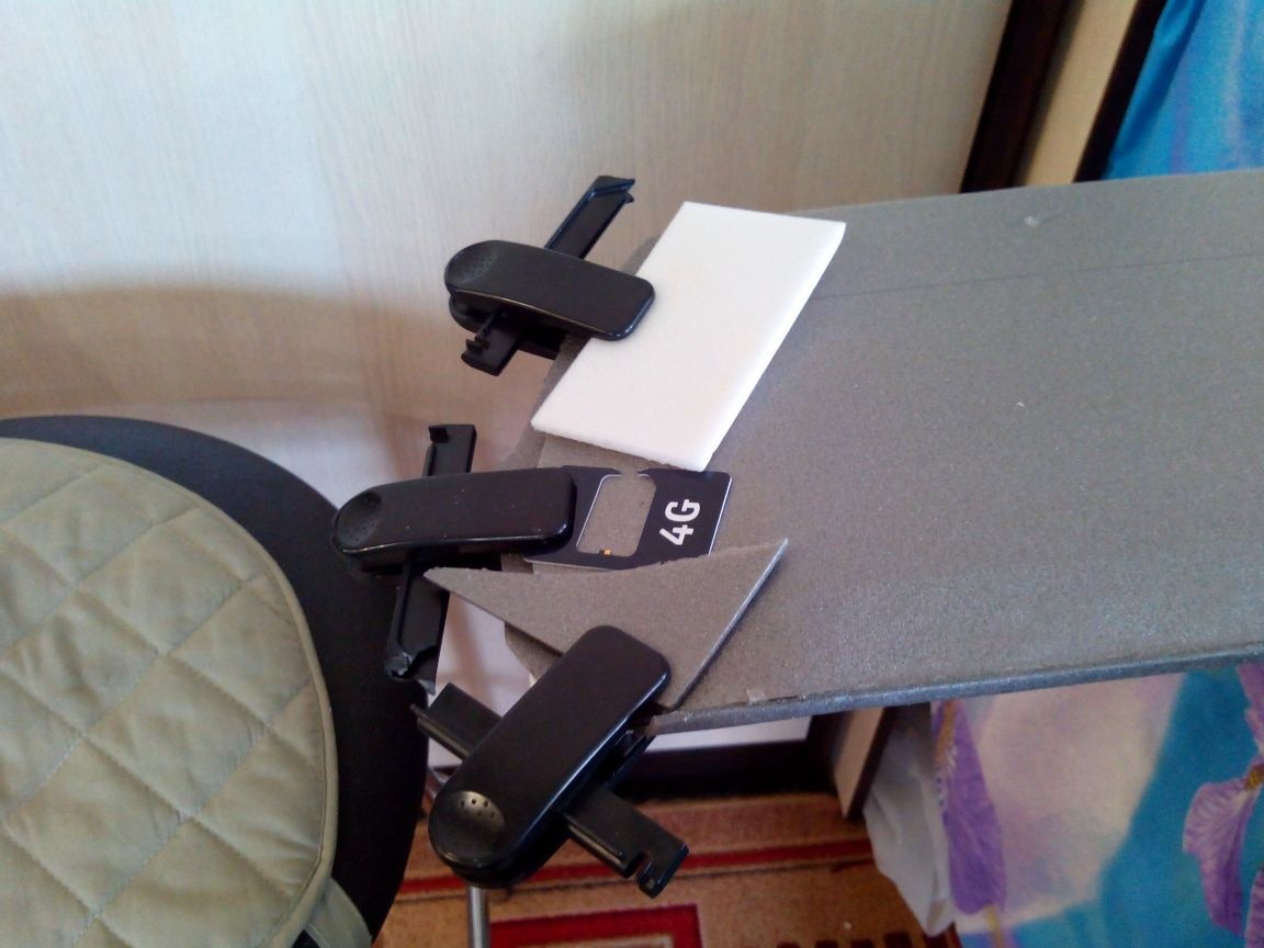
The platform for the self-tapping screw, to which the rear part of the wing will be screwed, is made of a foam block and a piece of plywood with small “fangs”.
It is glued to the fifth frame already after cutting out the space under the wing.
In the tail section, we make a cutout for the stabilizer - above the central stringer.
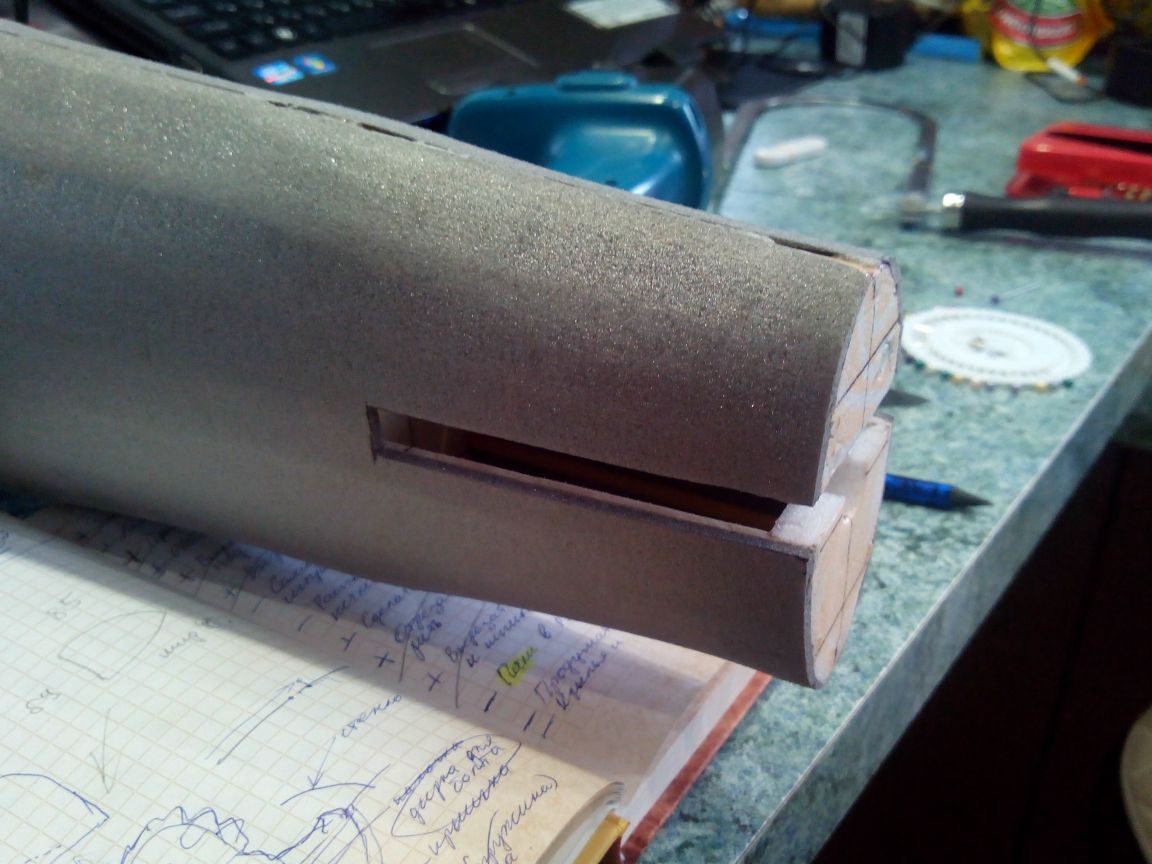
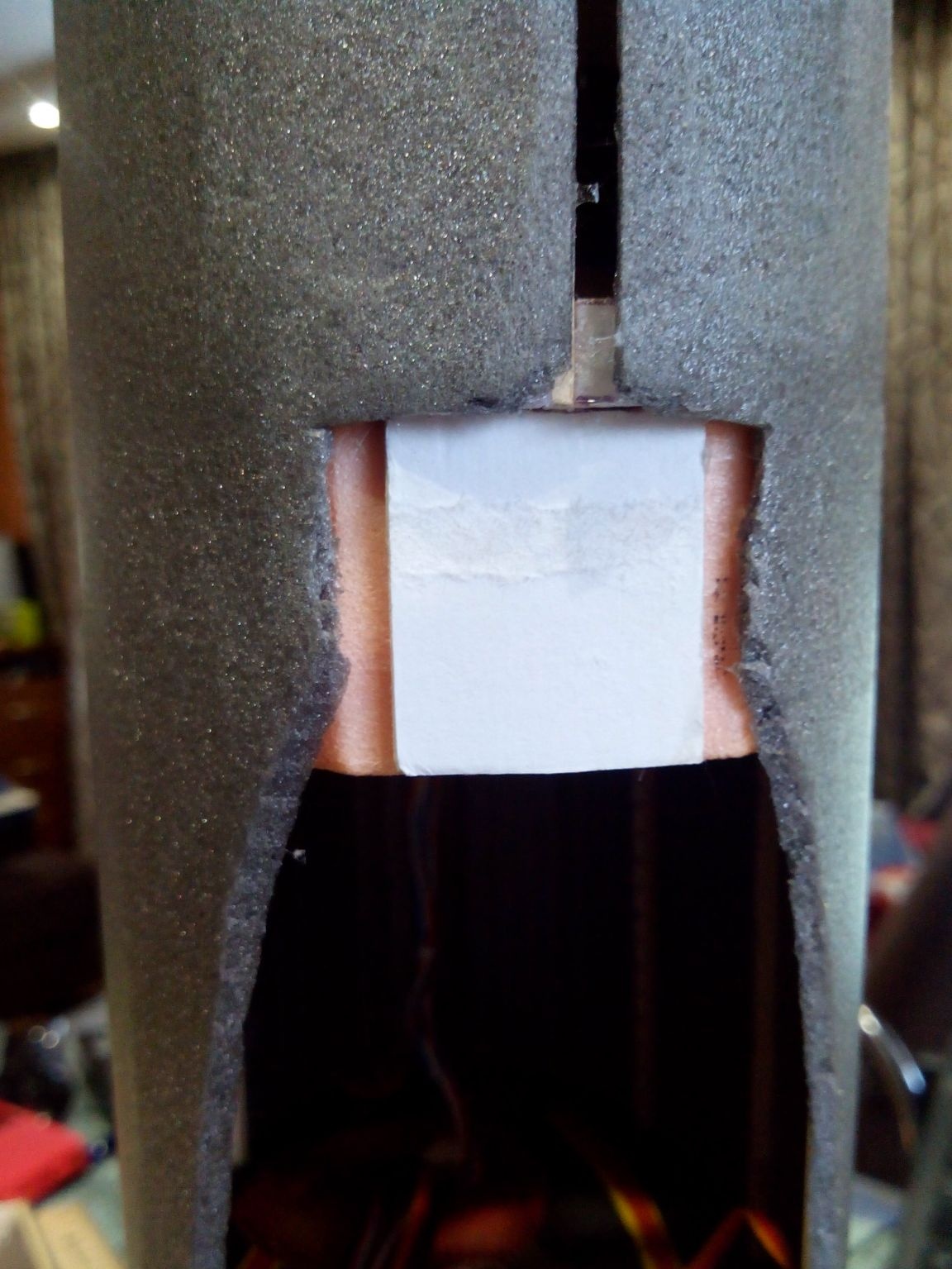
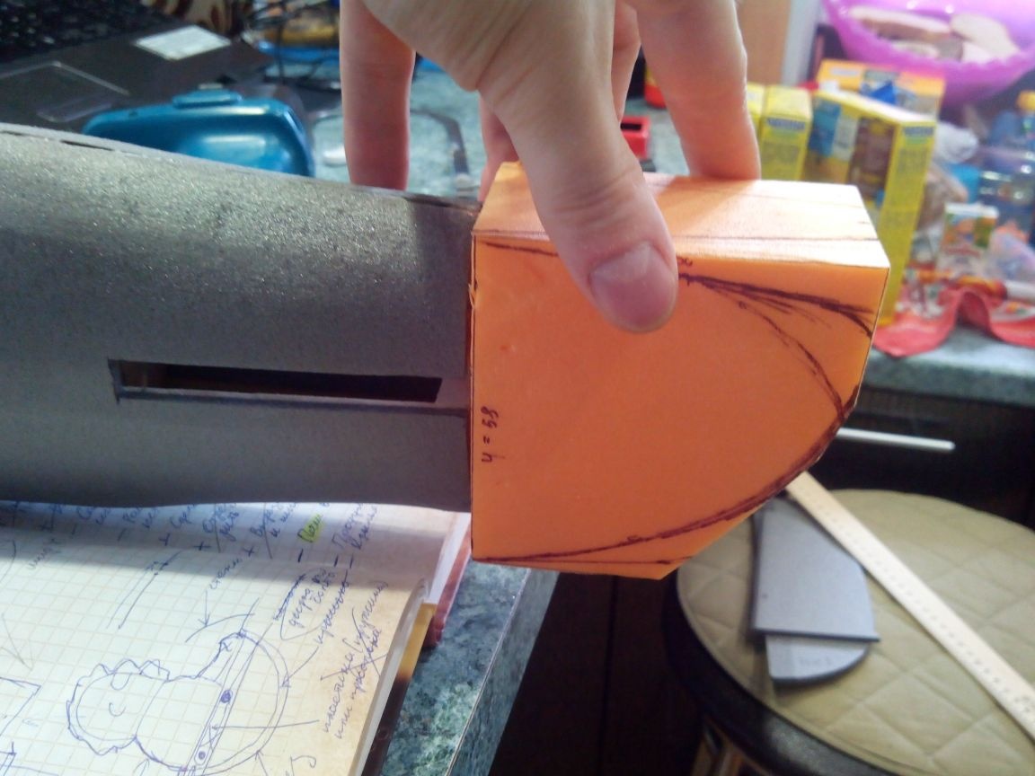
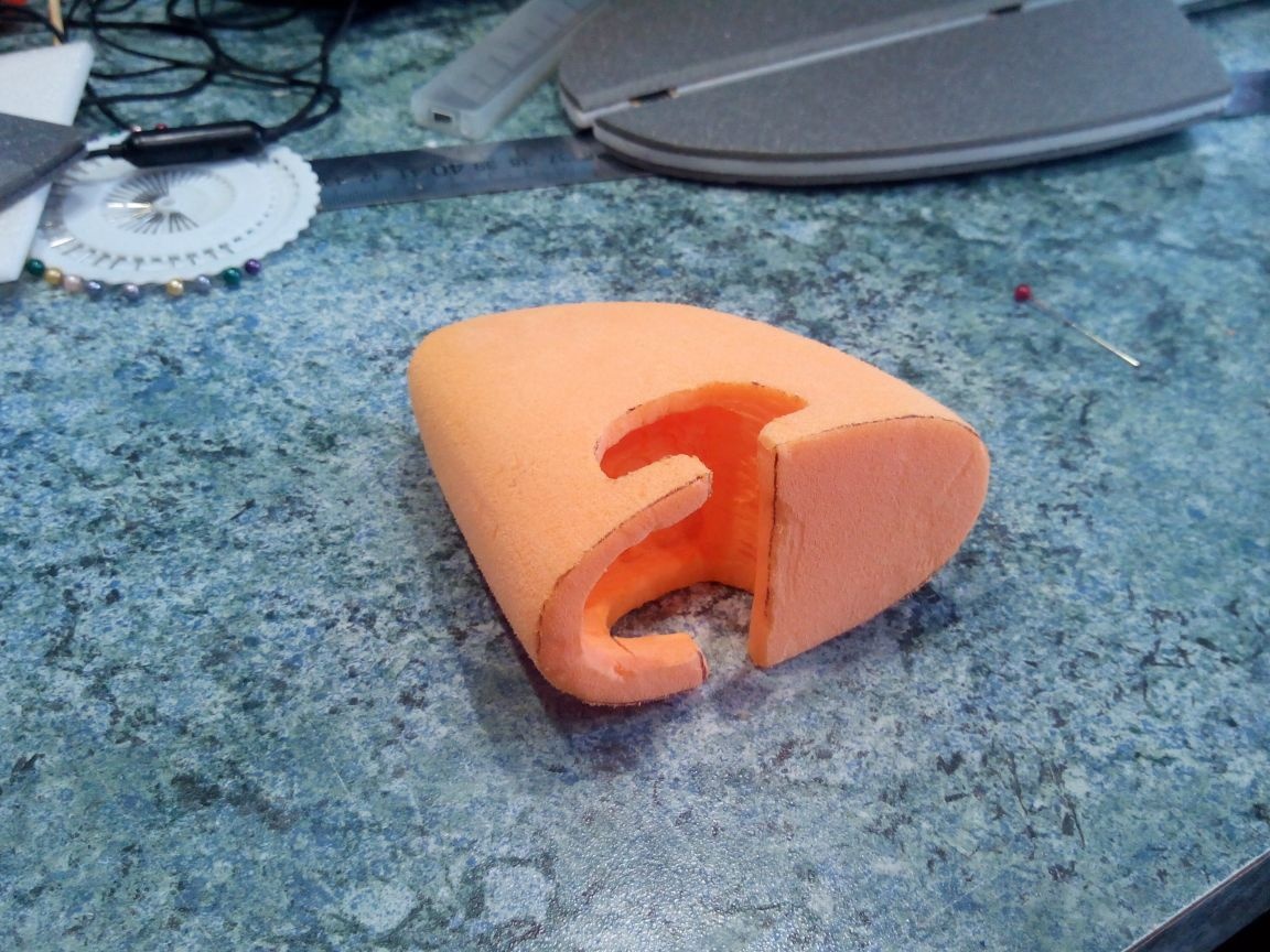
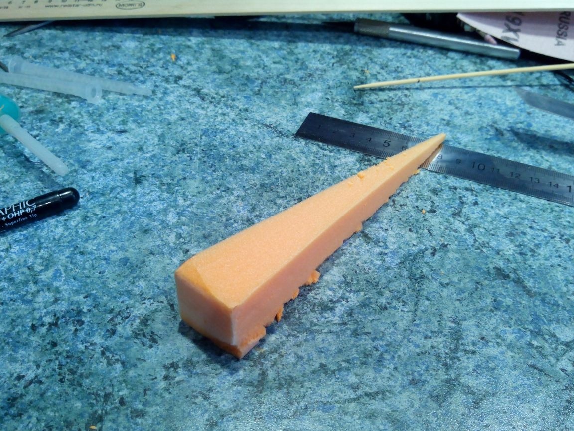
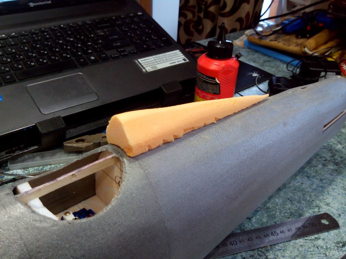
From the foam, we cut out the end of the fuselage - the cone.
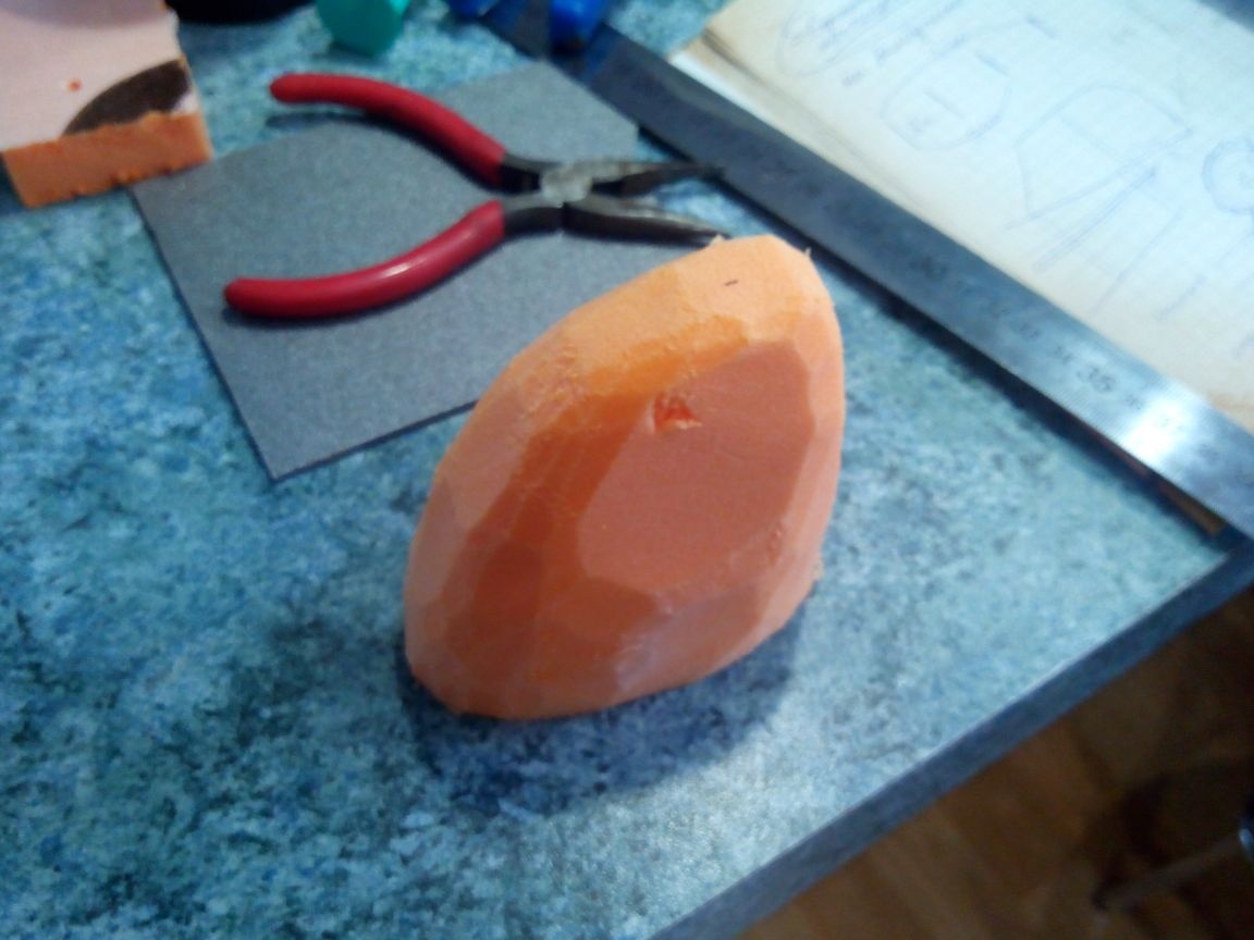
We give it the final shape with an emery cloth and do a dremel inside the recess under the steering boars.
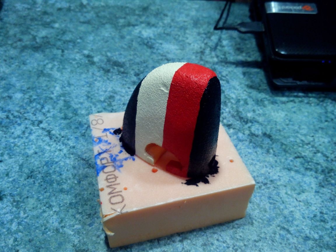
We paint the cone in the colors of the rudder with acrylic paints.
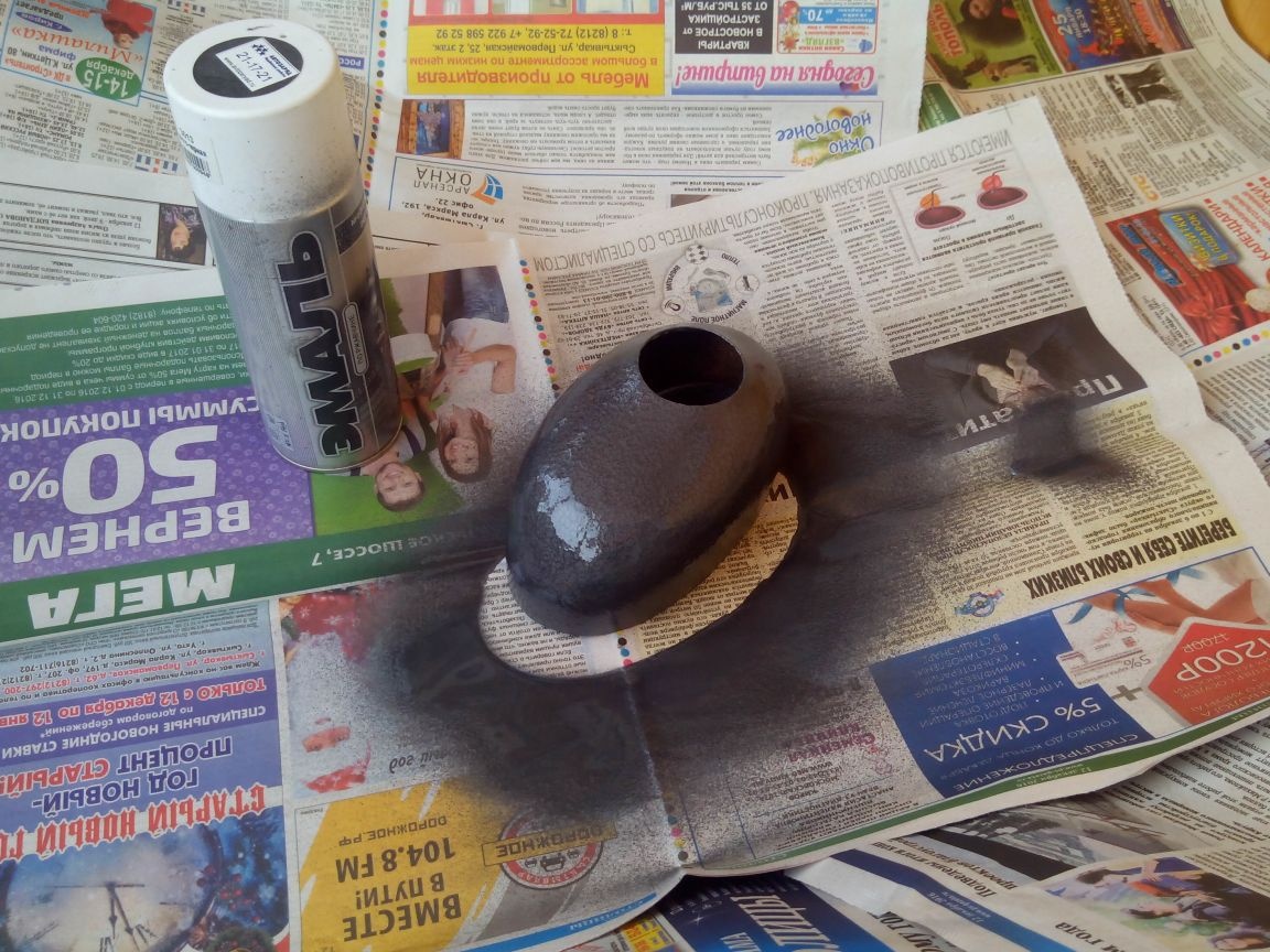
I already talked about how to make a hood in this article: Hoods and lights for tights and epoxy models
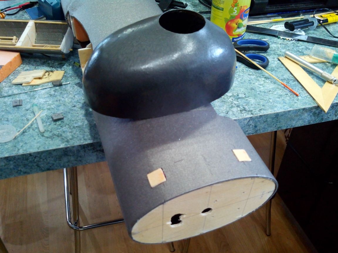
I decided to paint the hood in the color of the fuselage - gray spray paint, but it is also possible with a marker.
In the bow of the fuselage, cut out small rectangles in the area of the stringers and paste pieces of plywood there. These will be the places for screwing in the hood fixing screws.
The pilot and his seat will also perform the function of the tailgate compartment lid.
First, we cut a hole above the servos in a circular pattern (between 5 and 6 frames).
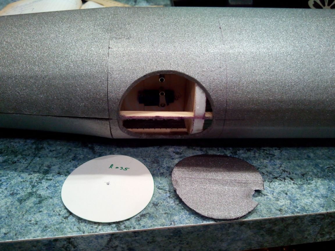
Cut out the details of the cover.
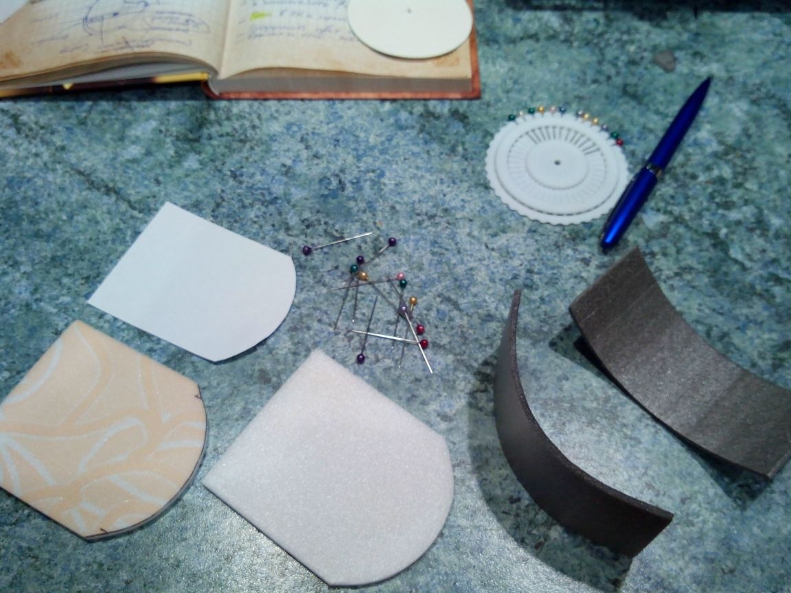
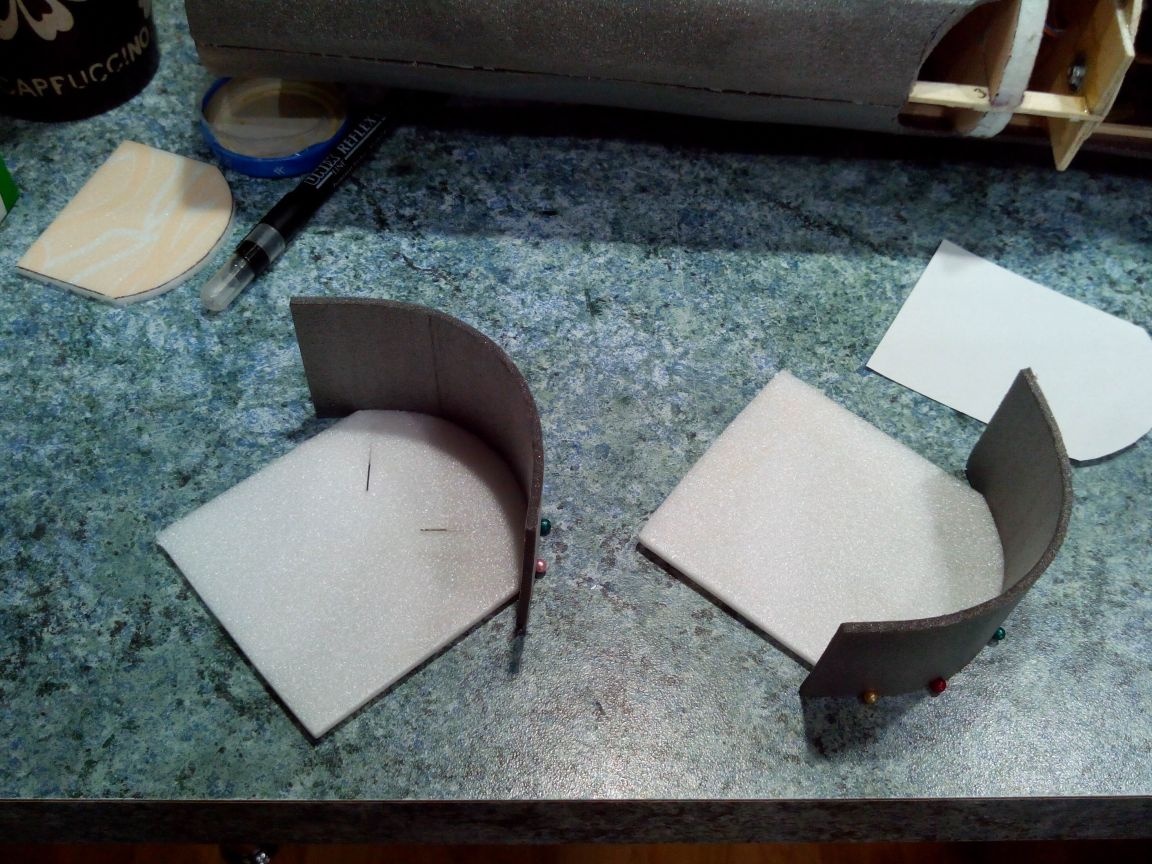
We glue the halves of the future cover.
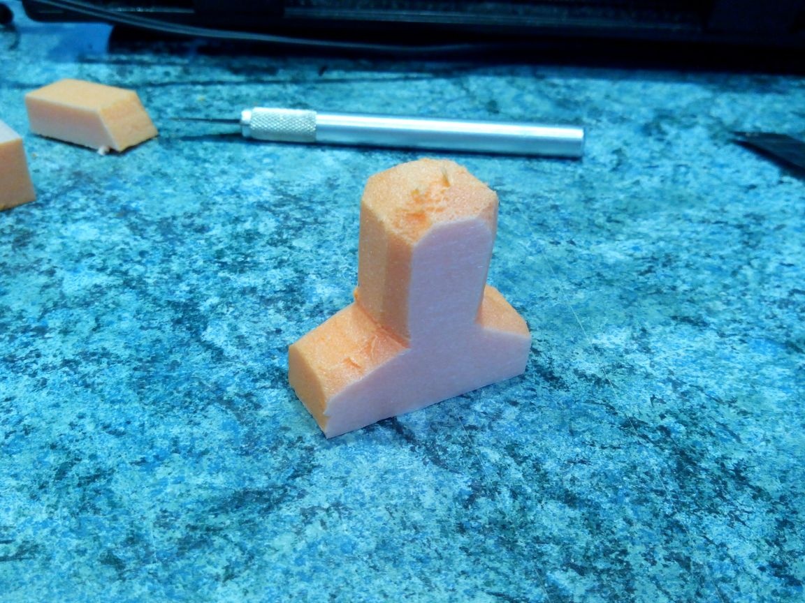
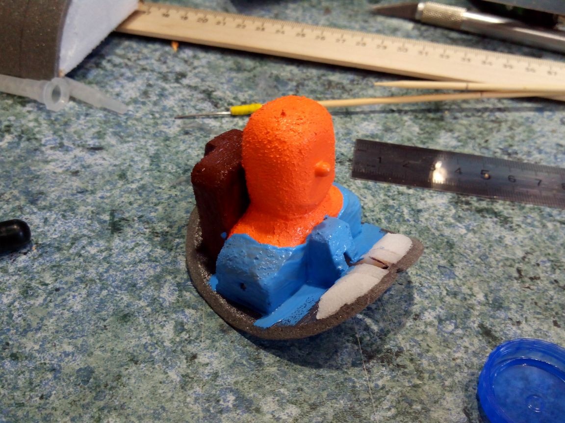
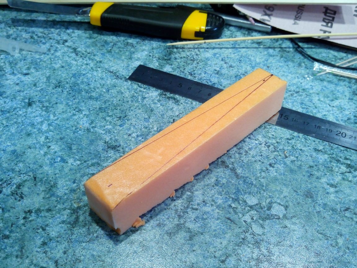
From penopleks we cut the pilot figure blank
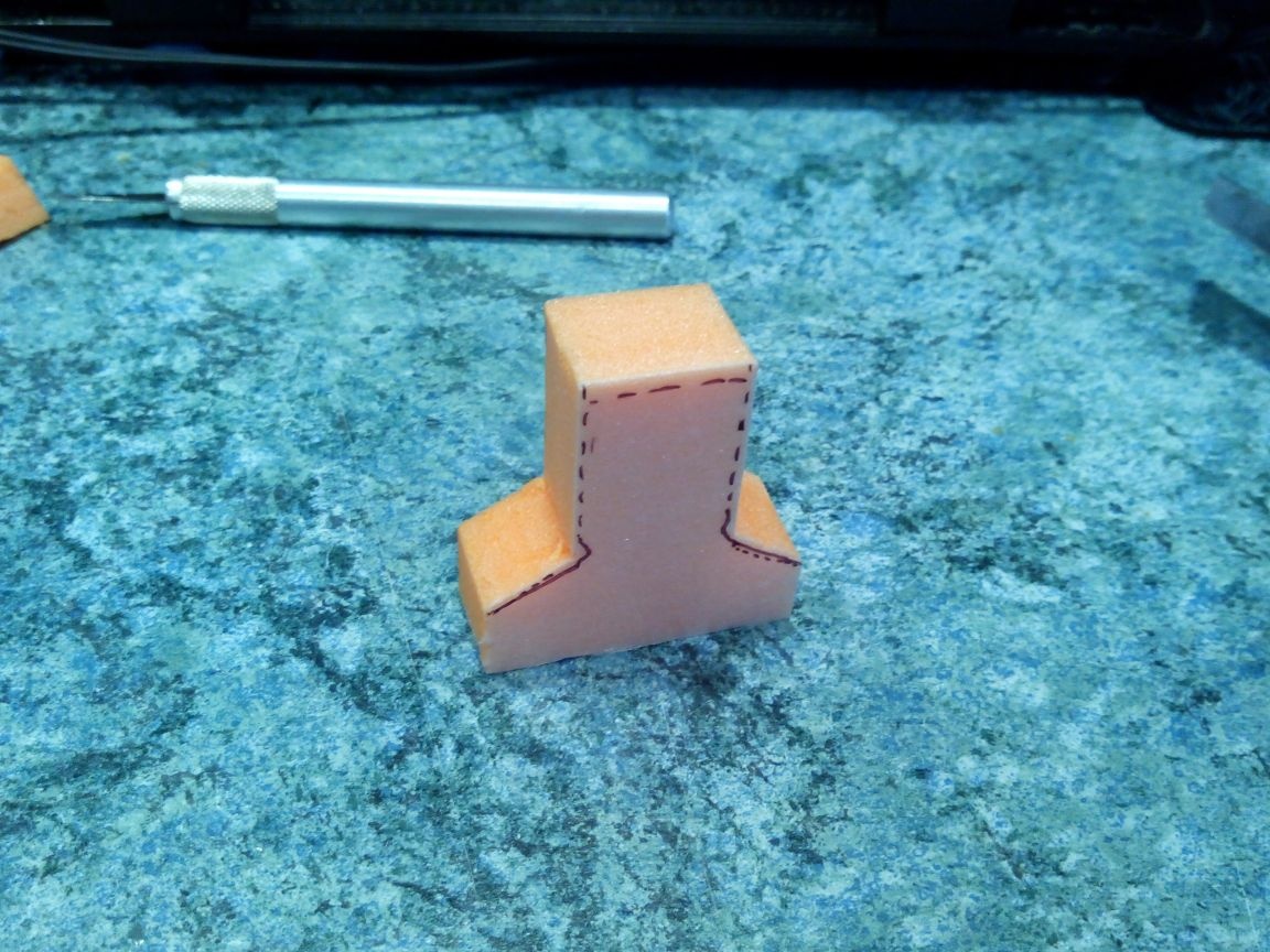
And we process it with a knife and sandpaper.
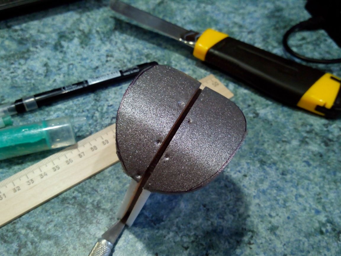
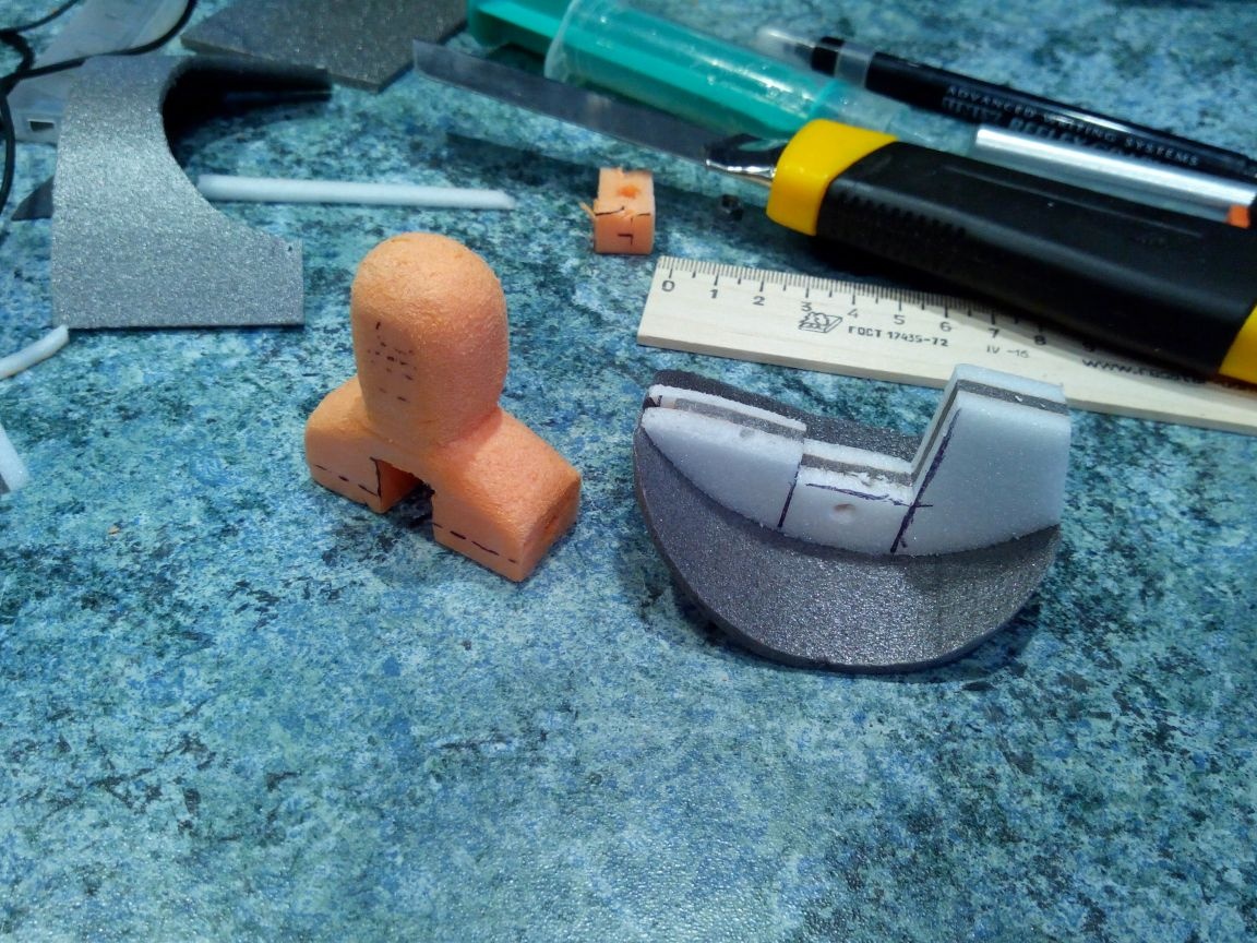
We cut the halves according to the shape of the hole and glue them by placing a piece of depron between them.
After the glue dries, we cut off the excess and make a cutout in the pilot.
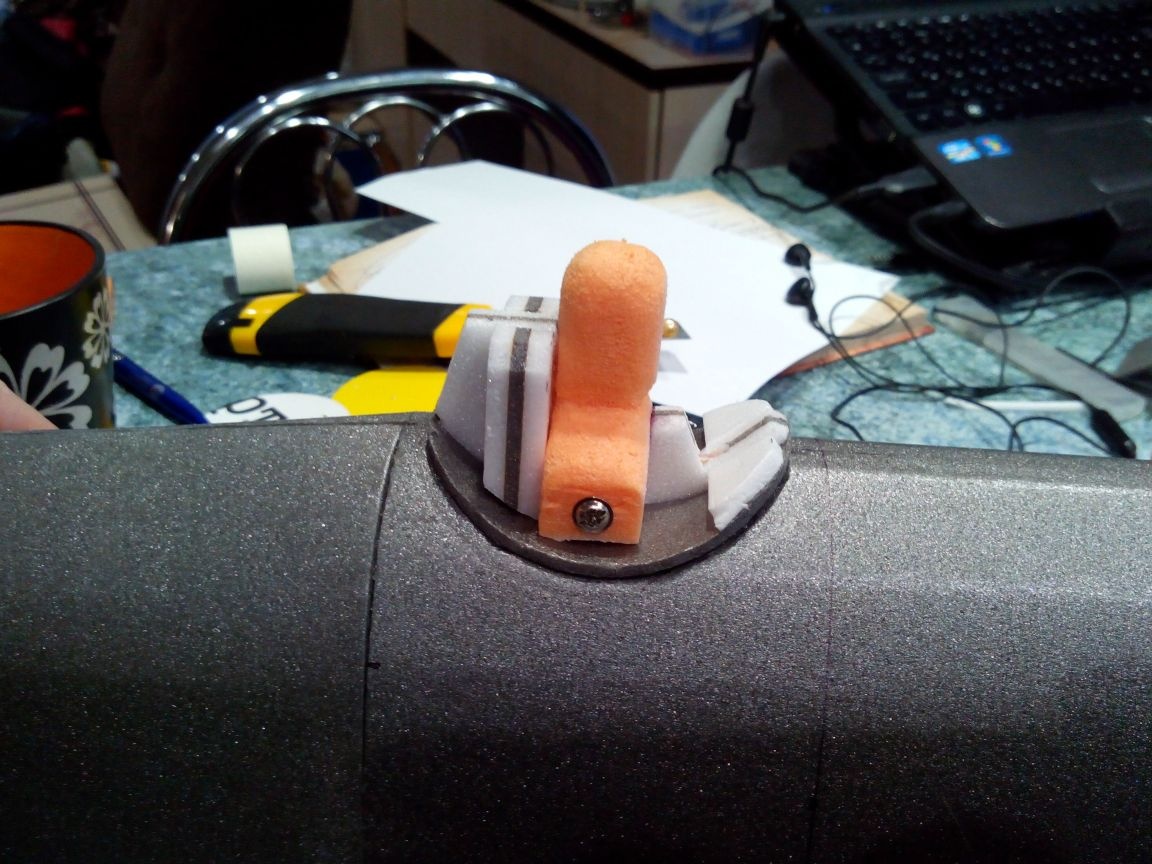
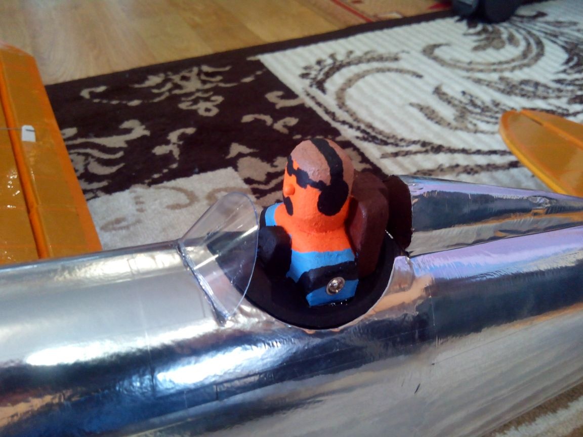
We glue the pilot and the back of the seat behind. In this photo, the principle of fastening the cap is also visible - a bolt passes through the entire pilot and through the hole in the stringer, onto which a nut is screwed on the other shoulder of the pilot.
After fixing the pilot and the cap, we process the edges with an emery cloth to even them with the fuselage skin. Then we paint the pilot and the seat with acrylic paints. The nose of the pilot is from a pin.
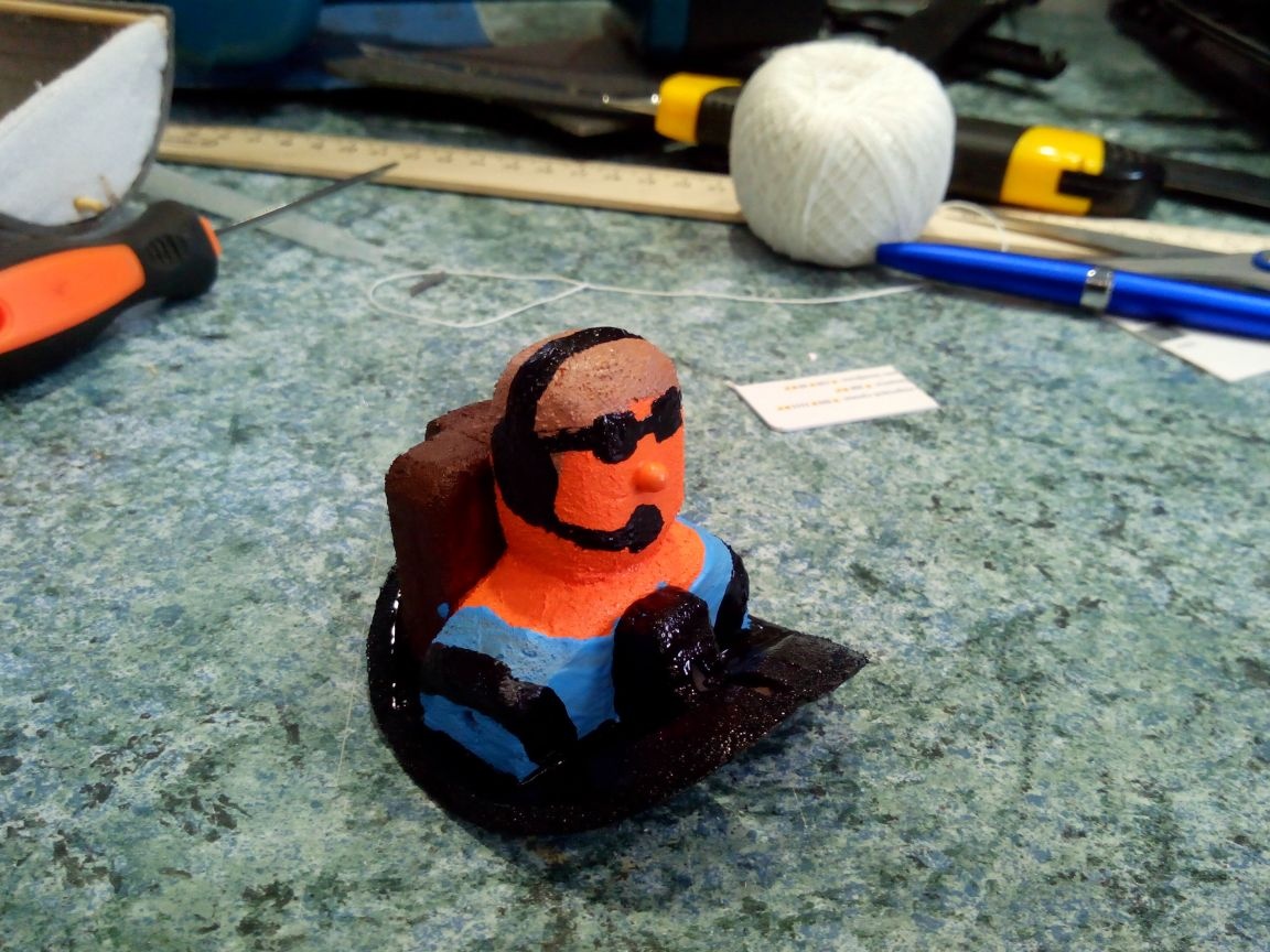
We make the head restraint from a foam block.
First, cut the workpiece with a knife
Then we sand and glue behind the cab.
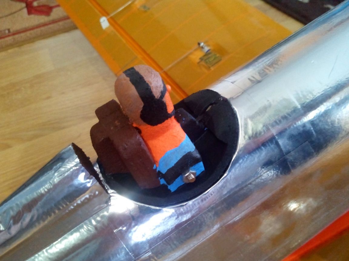
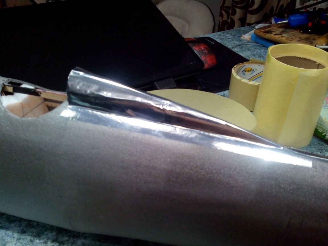
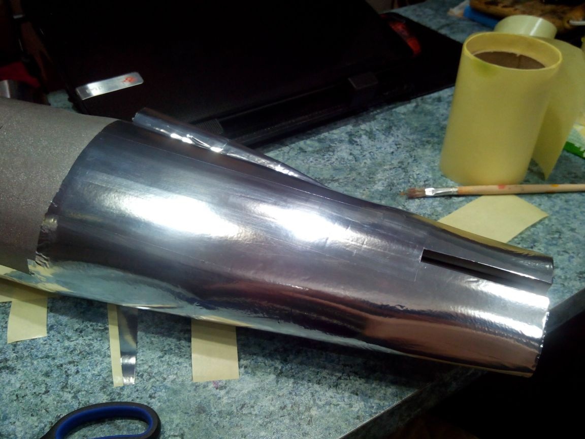
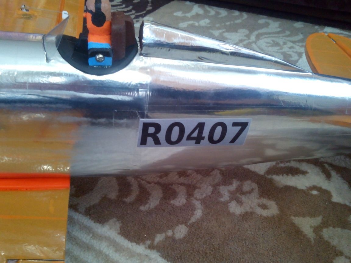
The fuselage decided to paste over with metal tape. Better to start from the tail.
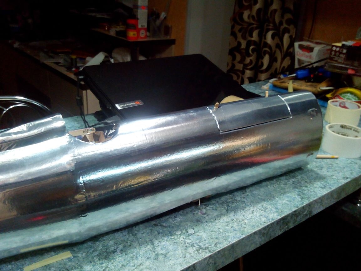
The windshield according to the template is cut out of a plastic bottle.
Then we clean the lower edge on both sides with an emery cloth and glue it onto the epoxy glue into a previously made slot in the fuselage.

You can finally screw the pilot.
Step 3. Making a wing
The wing on this model will be solid, in addition, landing gear will be attached to it. To me car allows you to carry this, but if you want, you can make the wing collapsible. The profile is flat-convex.
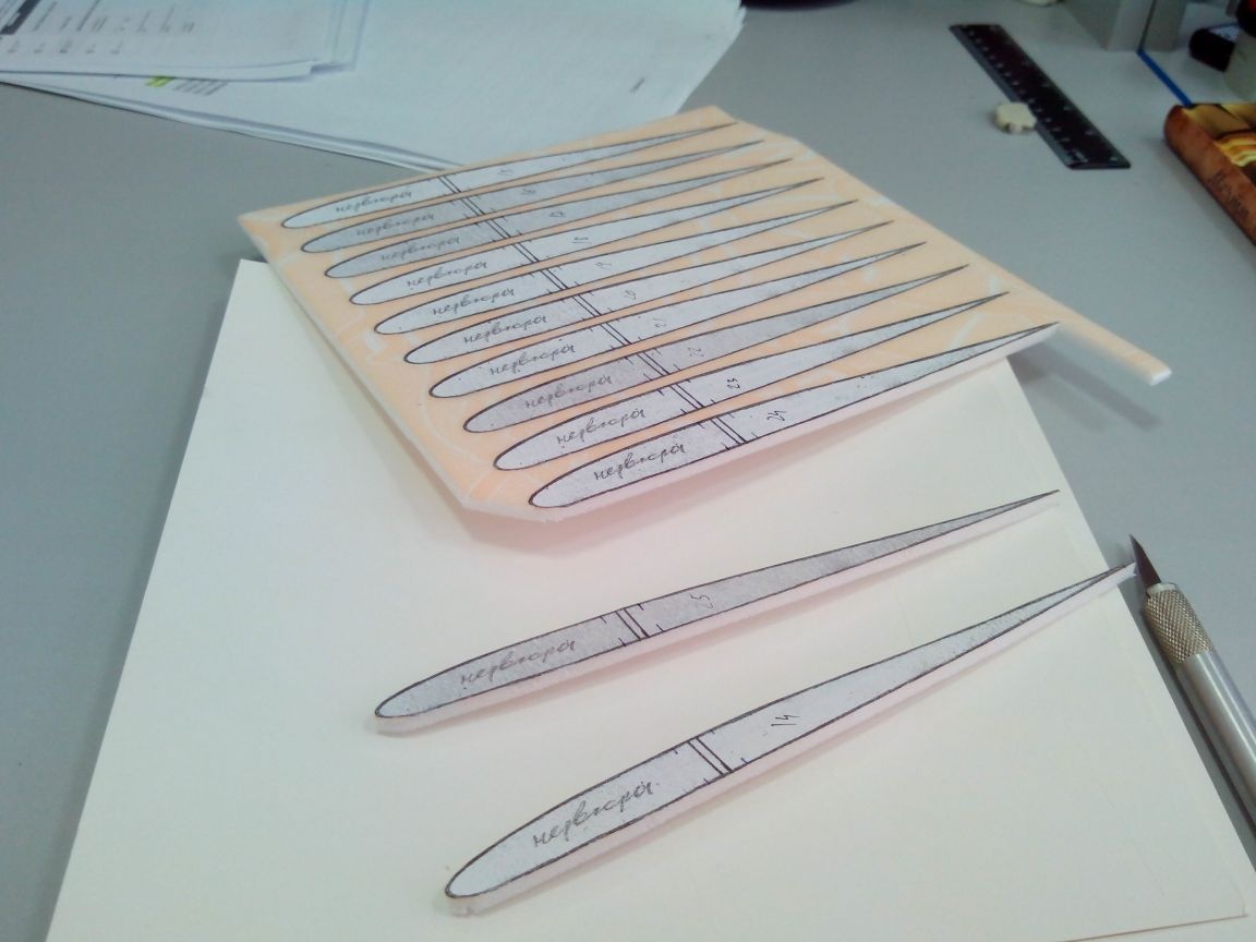
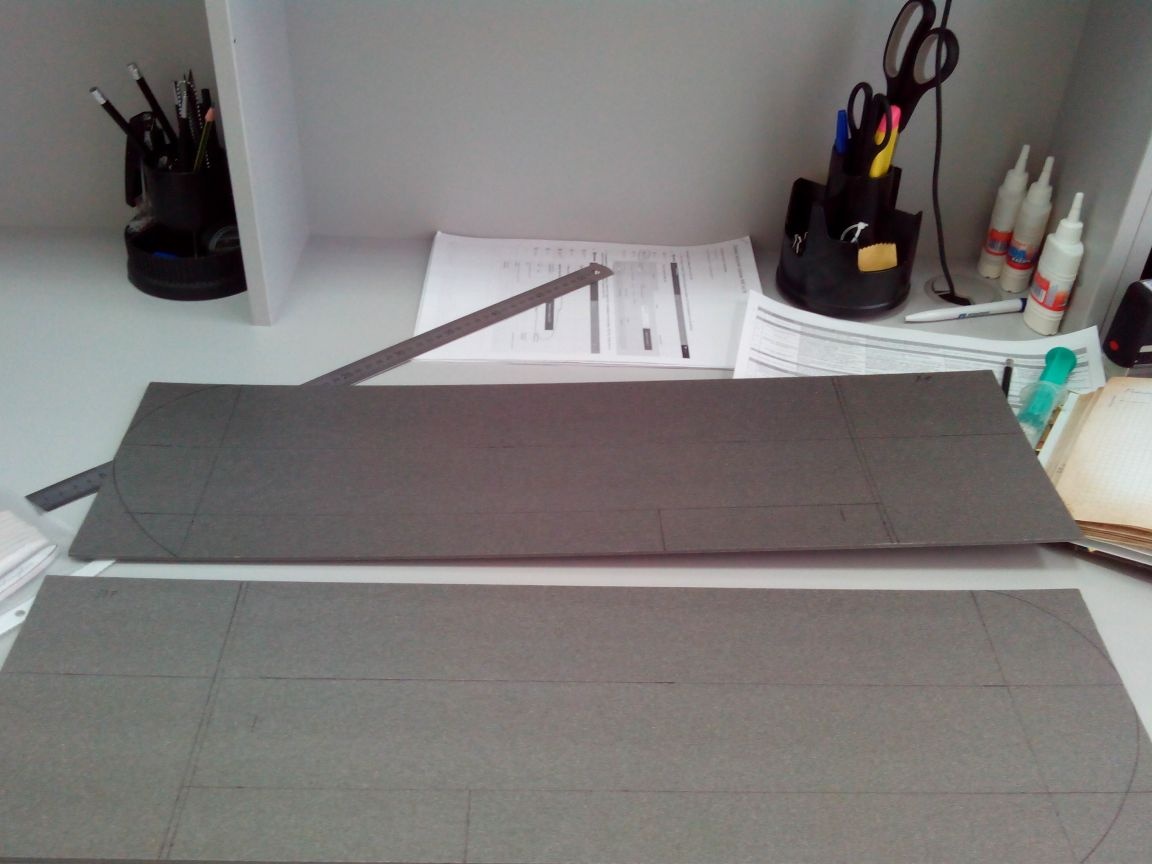
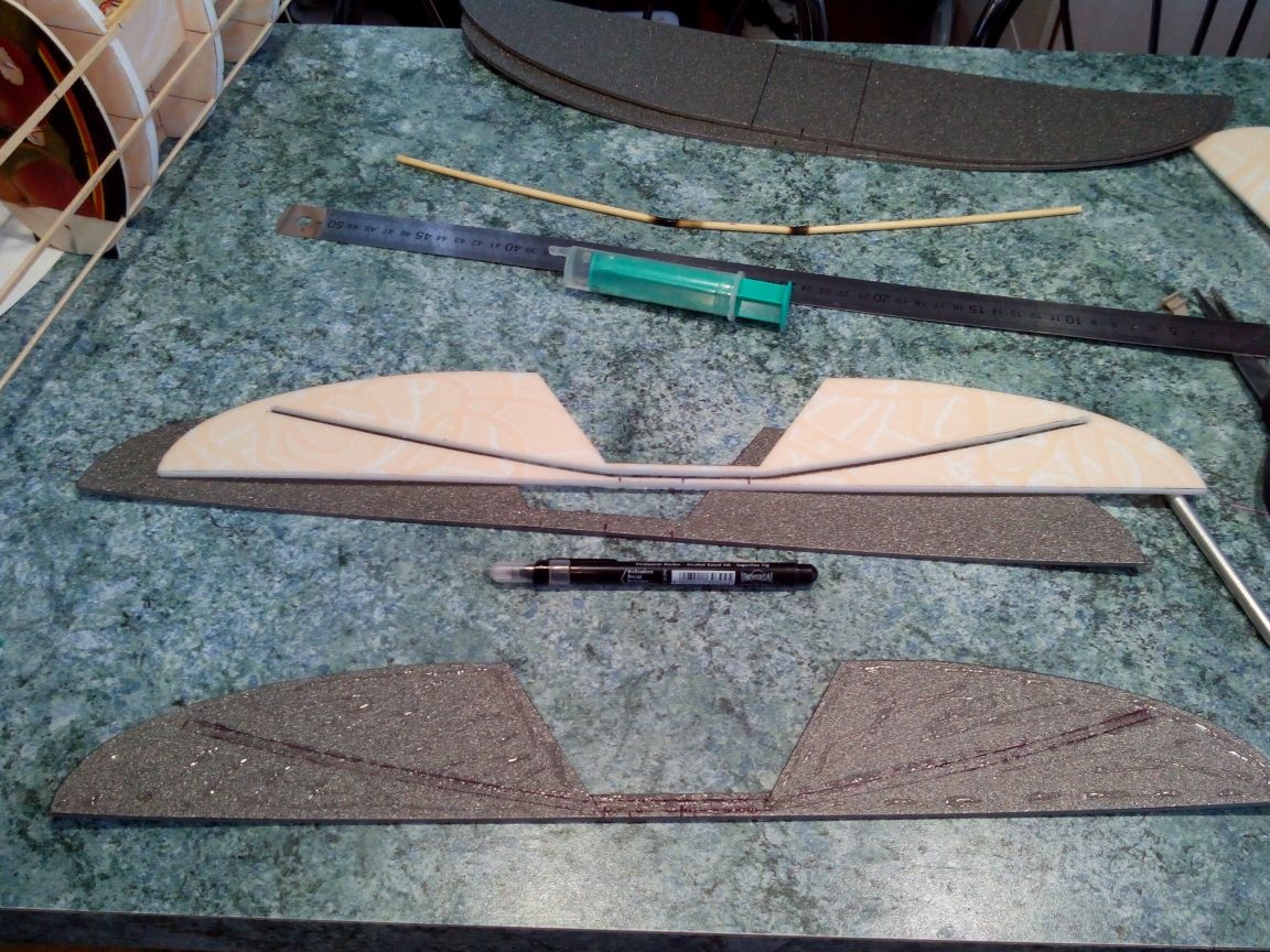
Cut the ribs patterns out of paper (I copied them on a copier).
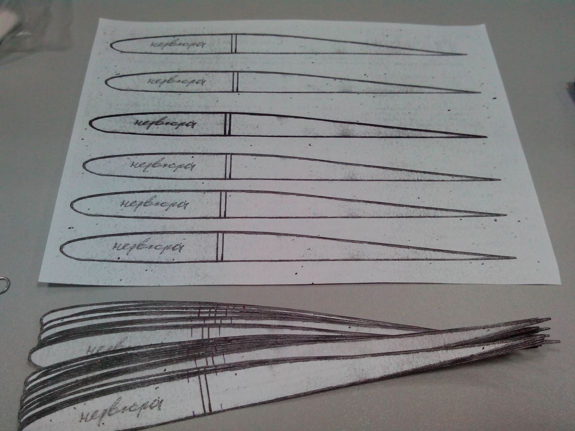
Glue them to the ceiling sheet.
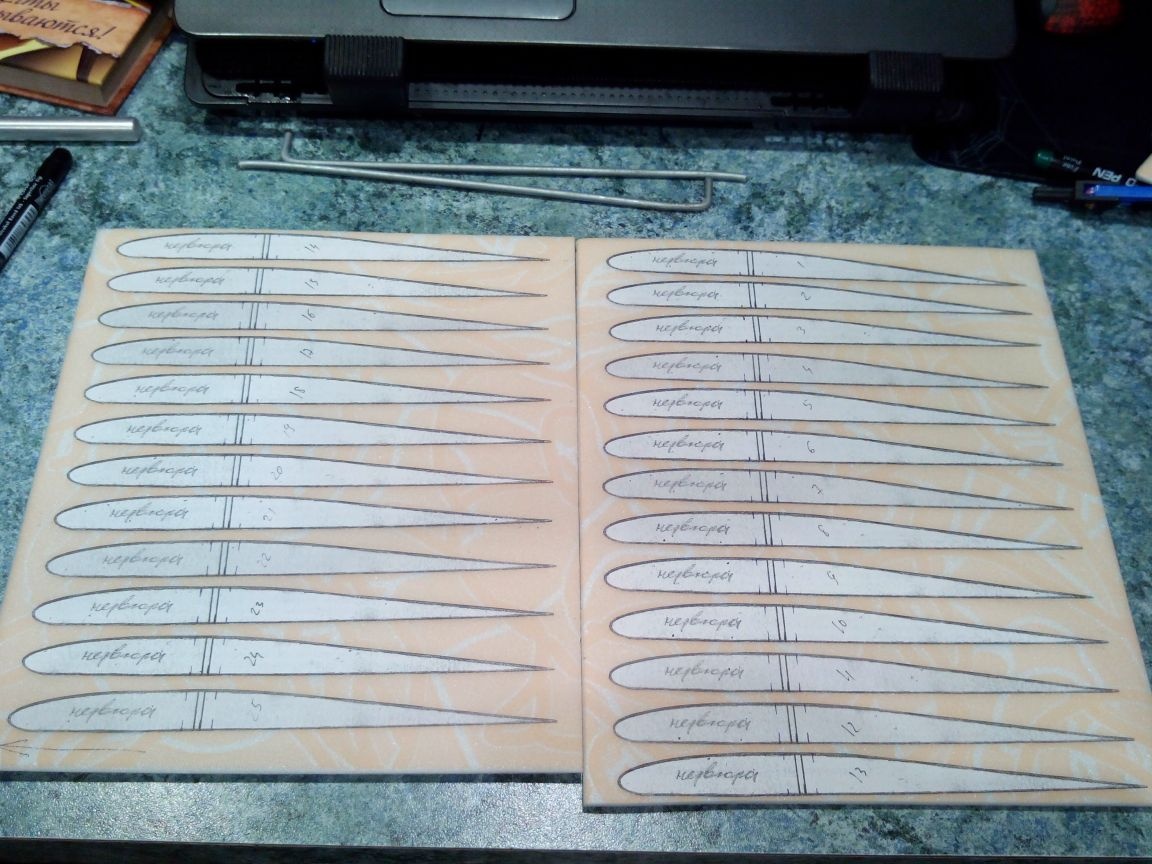
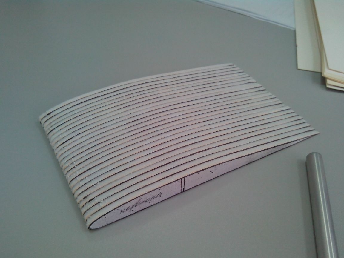
Cut with a cutter.
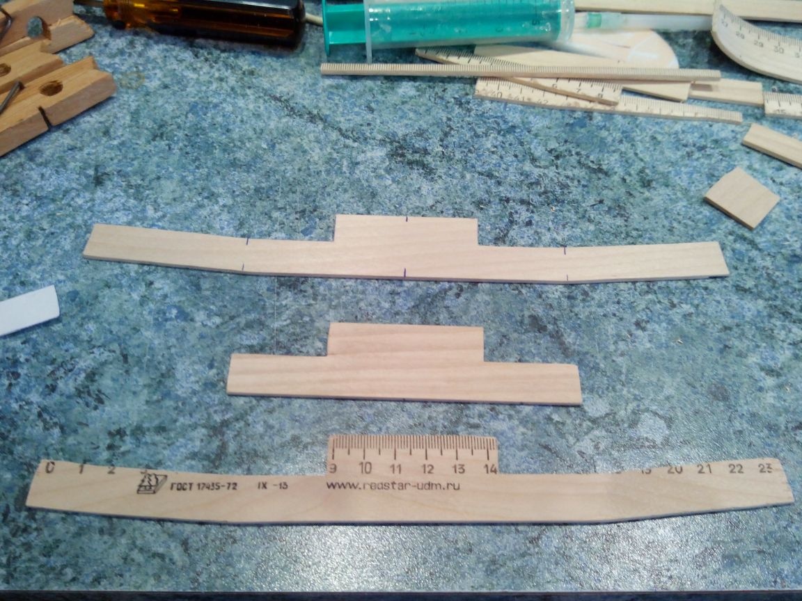
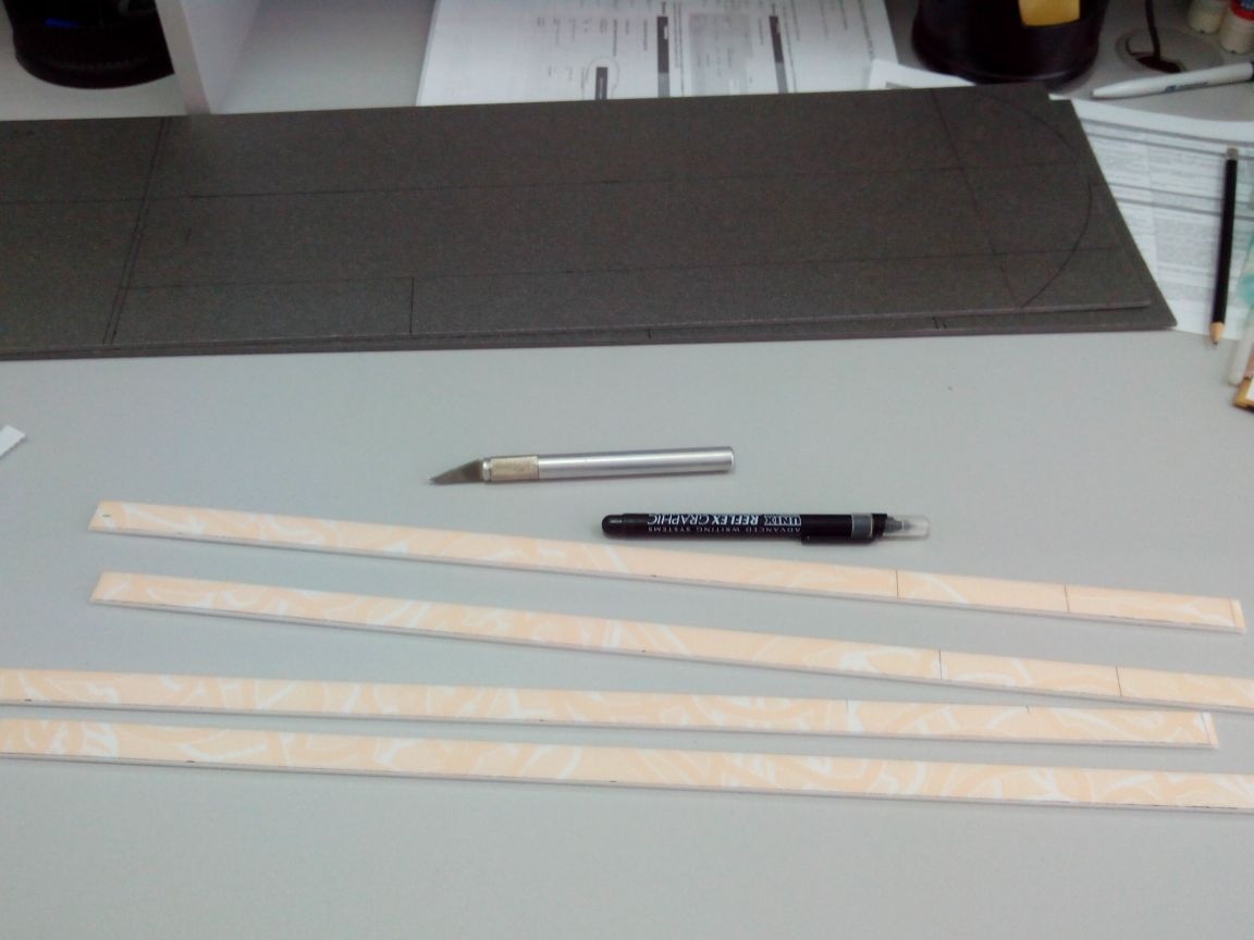
Spar from a wooden ruler.
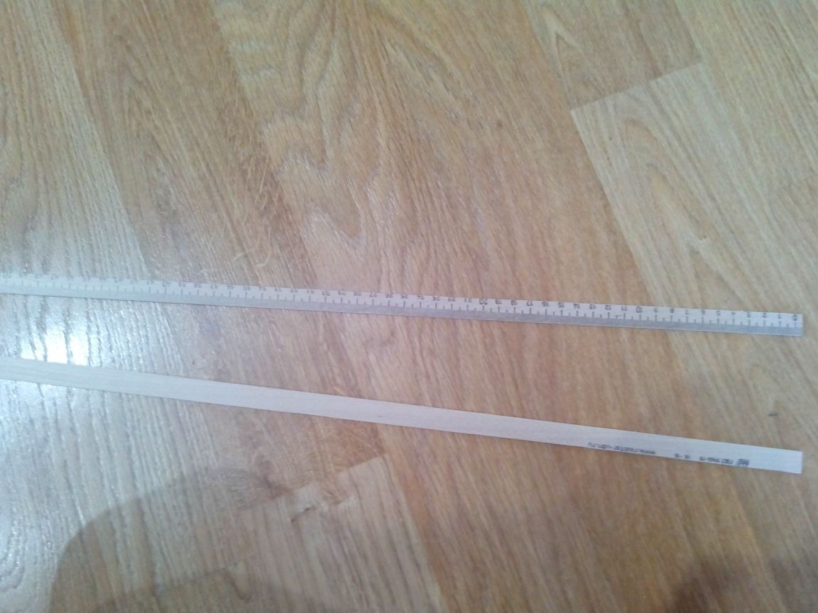
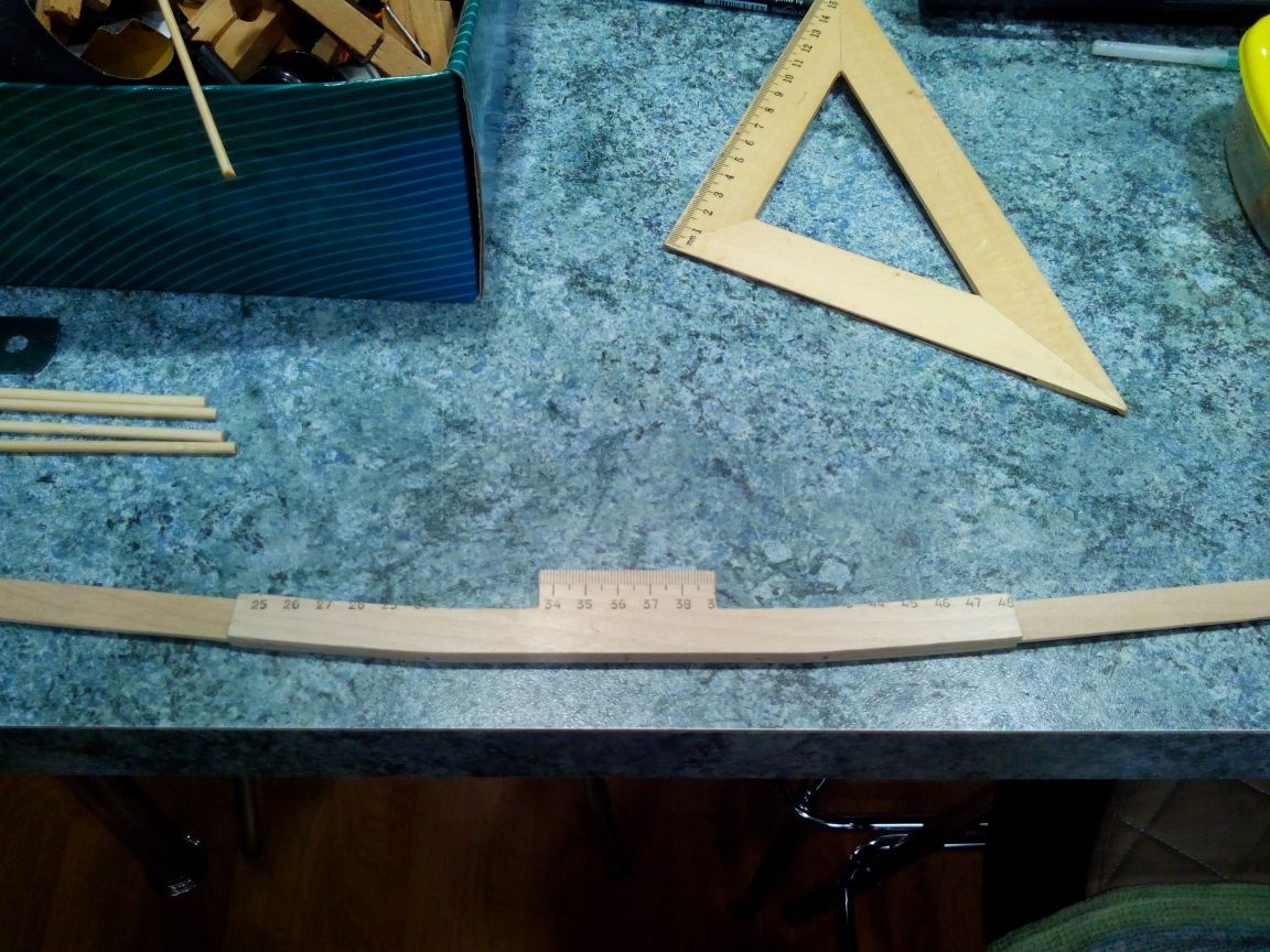
We also make the central part from the ruler according to the template.
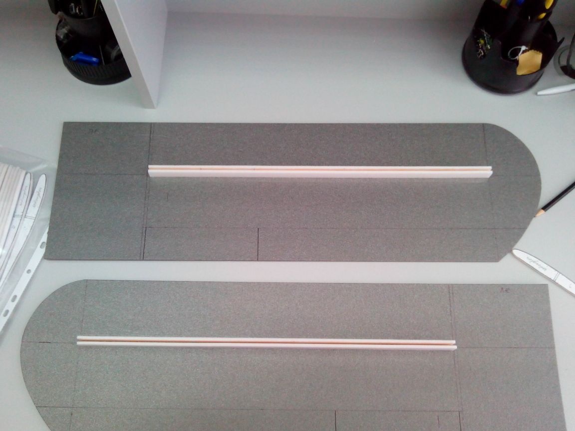
We glue the spar with PVA glue.
In the following photos, the spar fitting and the principle of fastening in general (on a bolt).
On the sheet of the depron we mark with the marker of the wing console, draw the line of the spar, flaps, ailerons and draw on the ending template.
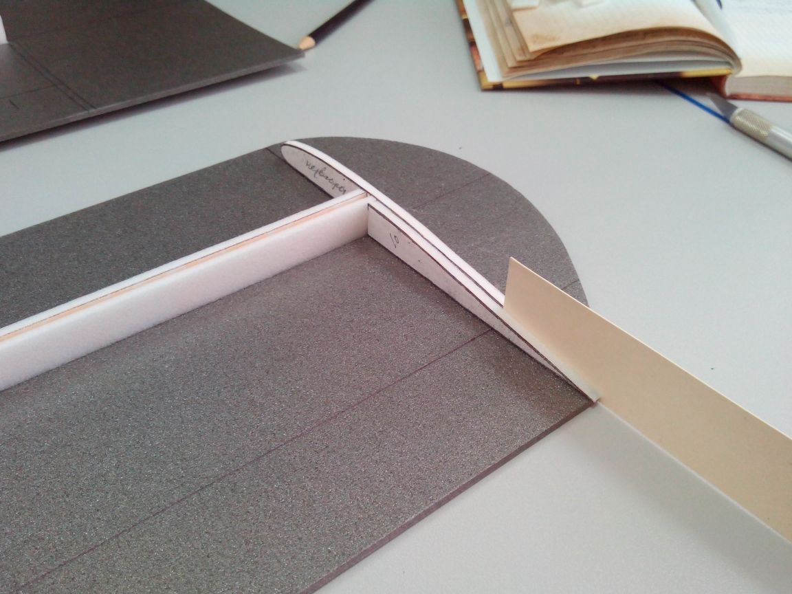
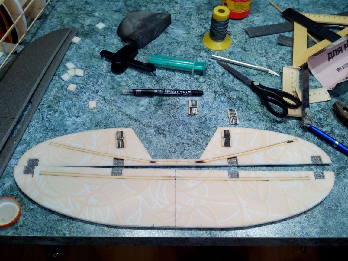
From the ceiling we cut the side members.
We glue the side members from the ceiling to the bottom and make cuts that will separate the flaps and ailerons.
Glue the first ribs.
The remaining ribs are cut into the nasal and tail parts and glued.
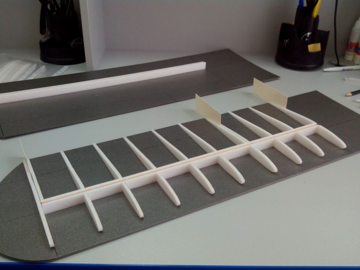
Similarly, we make the second console.
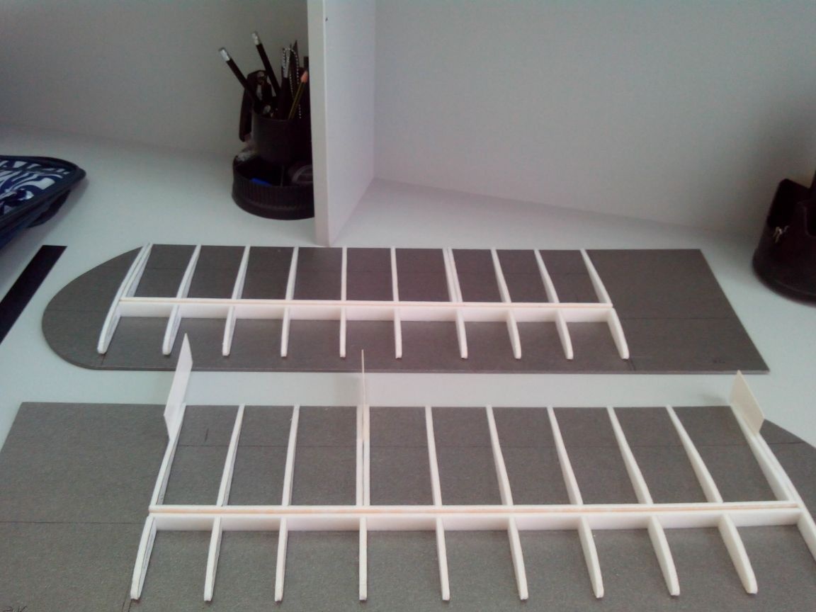
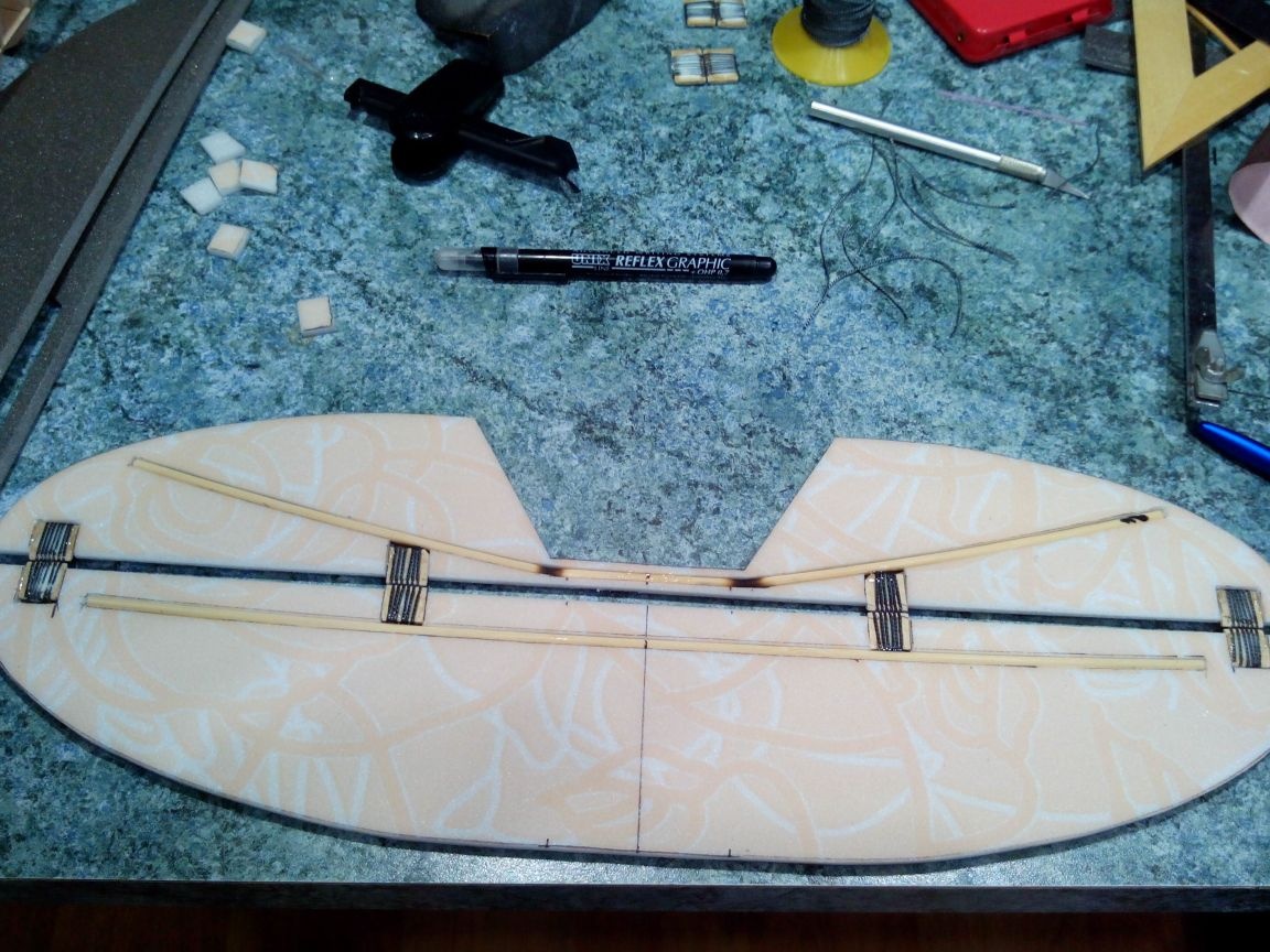
We arm ourselves with patience and glue another spar between the ribs, it will also be the boundary between the wing and the ailerons and flaps.
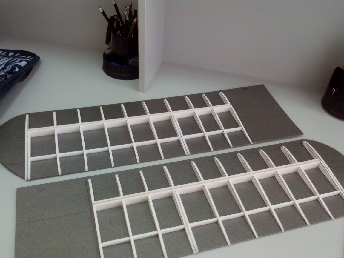
Glue the front edges of the flaps and ailerons. I inserted papers so that later it would be easier to cut.
Try on the wing console to the fuselage.
Closer to the center of the wing we glue ribs of 3 mm plywood and small plywood pads (this is a power element under the landing gear)
We glue the spar from the line.
Chassis rack made of thick steel bar. I tried to depict the principle of fastening in the photo.
We fill both racks with epoxy inside the wing.
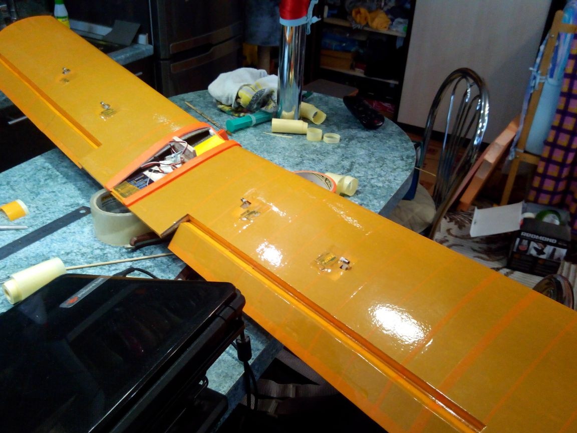
Getting to the servos.
We make landing sites for them from the ceiling.
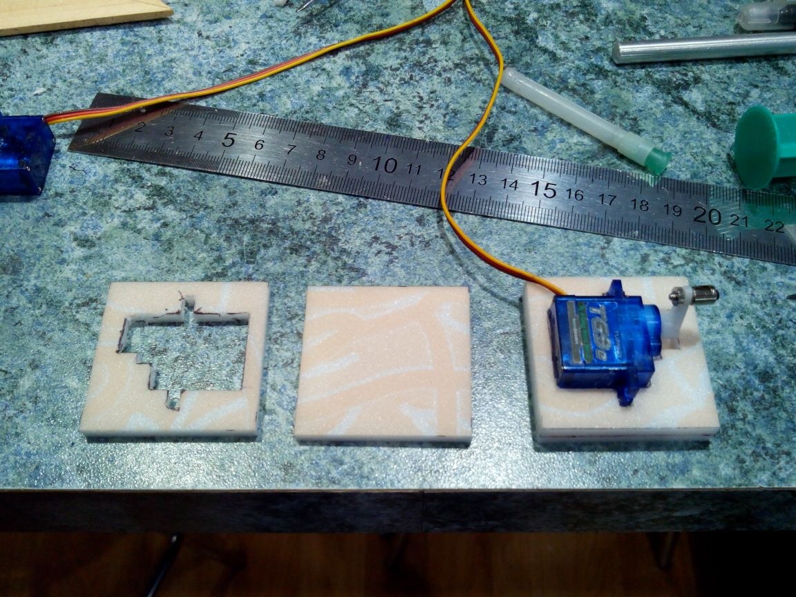
We glue the servos into these areas with hot-melt adhesive, and all together on the ceiling glue between the ribs.
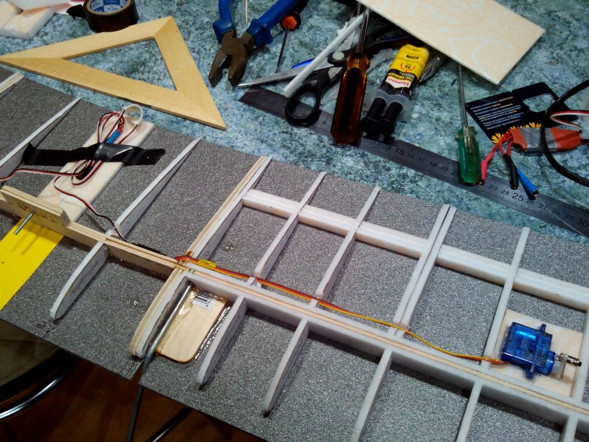
We pull the wires through small recesses in the ribs and fix it with hot glue.
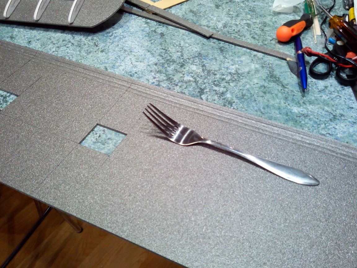
We cut out the upper parts of the wing sheathing from the depron, cut out hatches for servos in them, and push the strip with the fork in the region of the leading edge.
On the outside, glue a strip of adhesive tape so as not to break the depron in the process of bending.
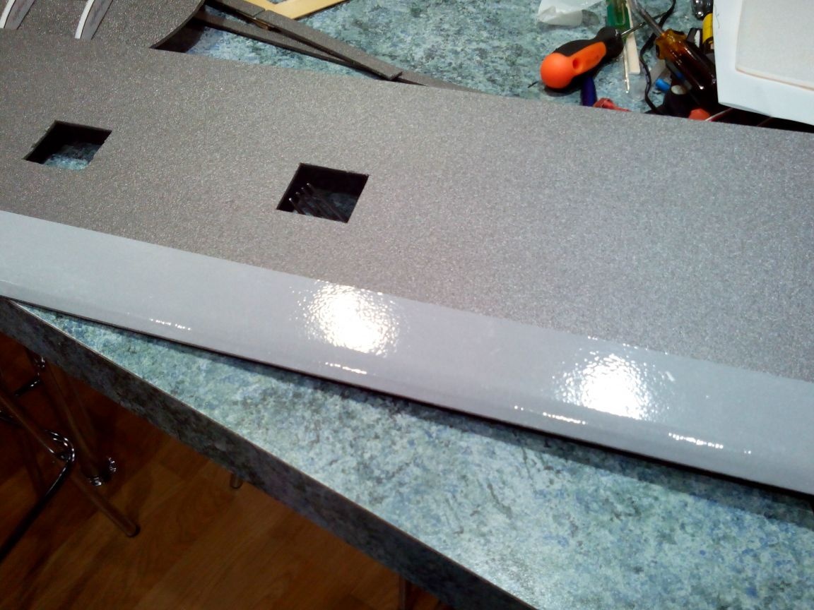
We smear the spar and the back of the ribs with glue and glue the top. We fix with electrical tape and clothespins.
After the glue dries, glue the front edge and fix it with tape along the entire length.
We seal the wingtips.
We cut off the excess depron at the tips, sand and cut the ailerons and flaps.
With a knife and sandpaper we process ailerons and flaps, grinding them at an angle of 45 degrees.
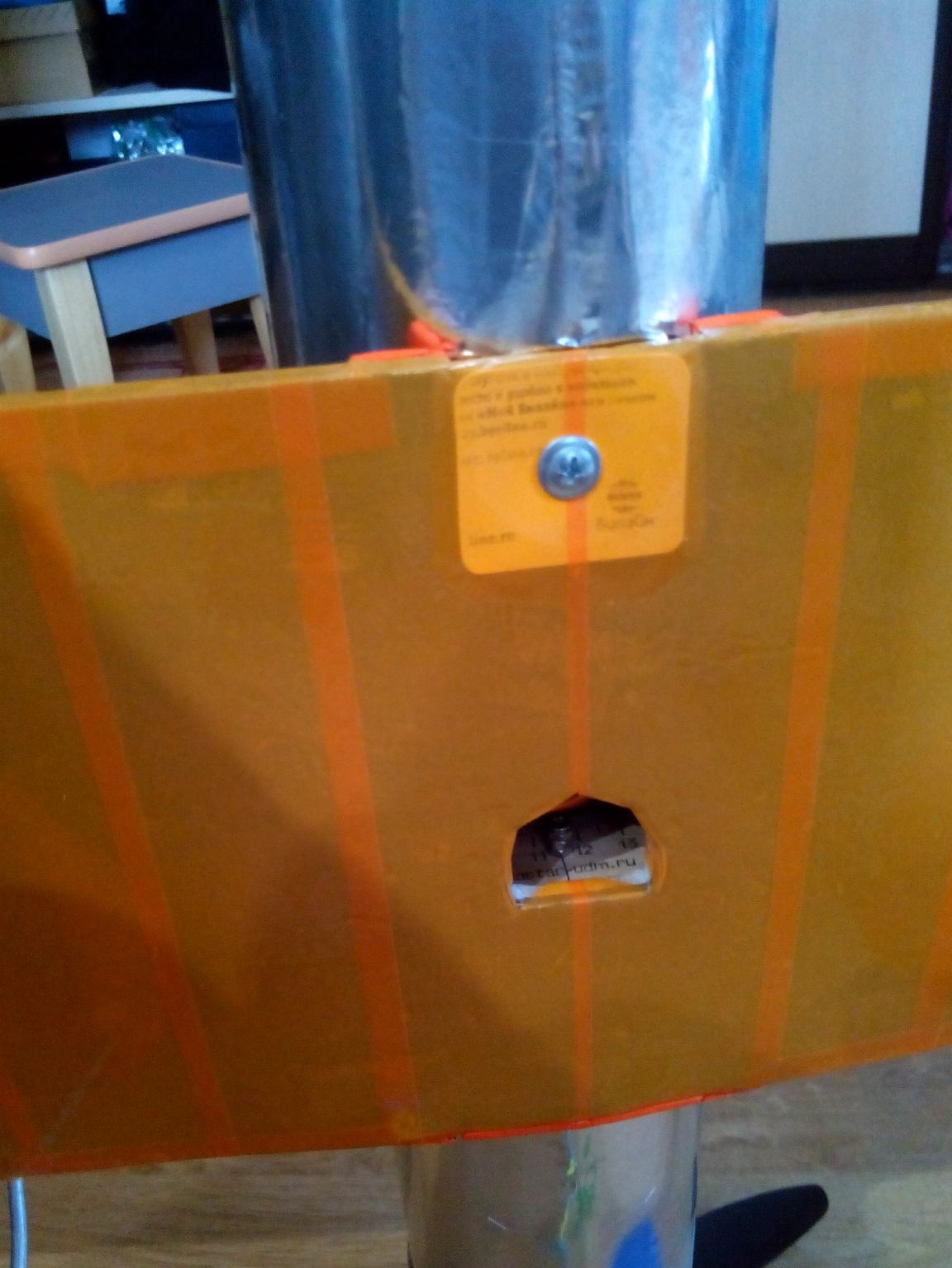
We fasten the wing to the fuselage, after making a hole in the fuselage, and glue the gaps from the strips of the ceiling tile.
Inside the wing, we glue a plate from the ceiling and a piece of plastic card for the future self-tapping screw on the joint over the spar. In front of the spar - a piece of cardboard.
We glue the wing with tape, putting the ailerons and flaps on it.
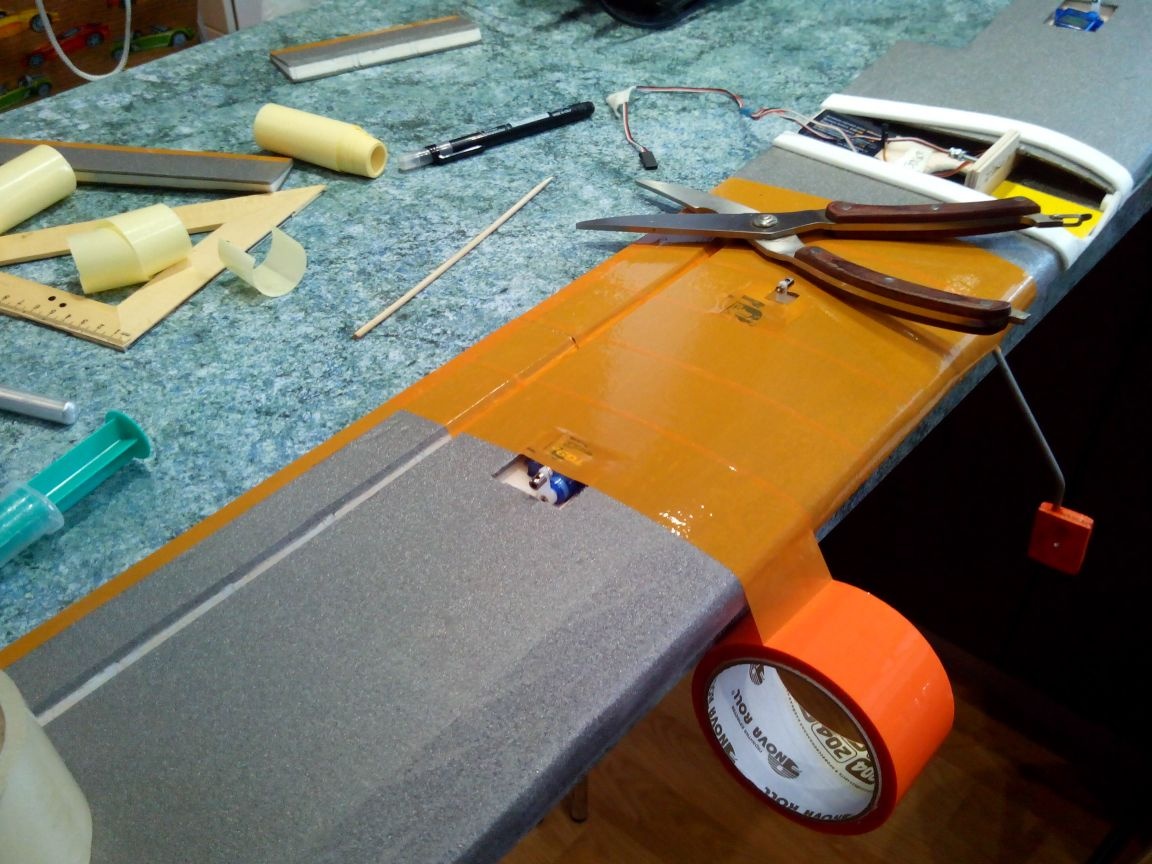
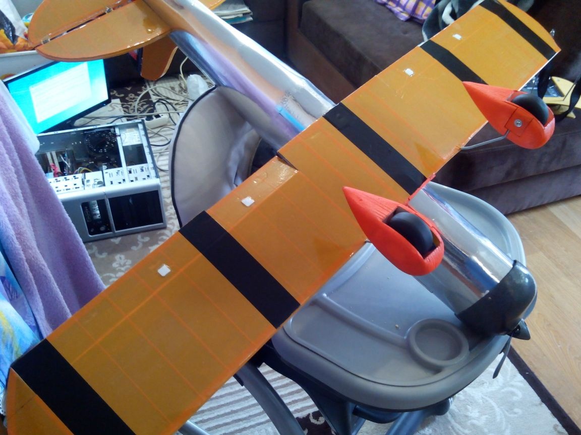
The bottom of the wing (for good readability of the model in the air) is decorated with stripes of black tape.
Paint the stairs with acrylic paint.
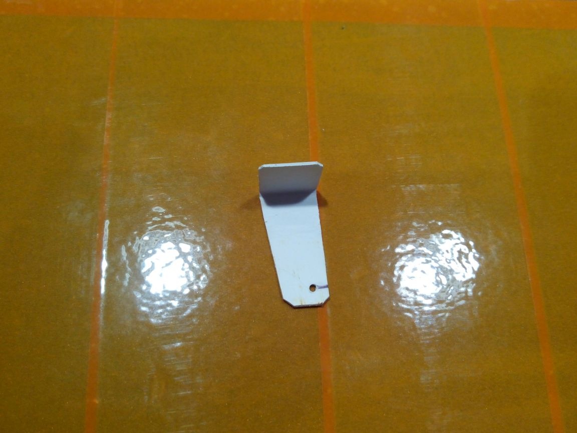
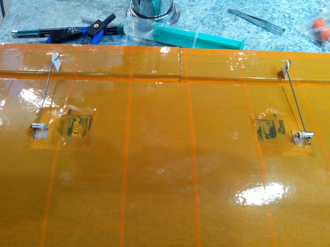
Home-made hogs from a building corner.
Steel wire rods, fastened with clamps.
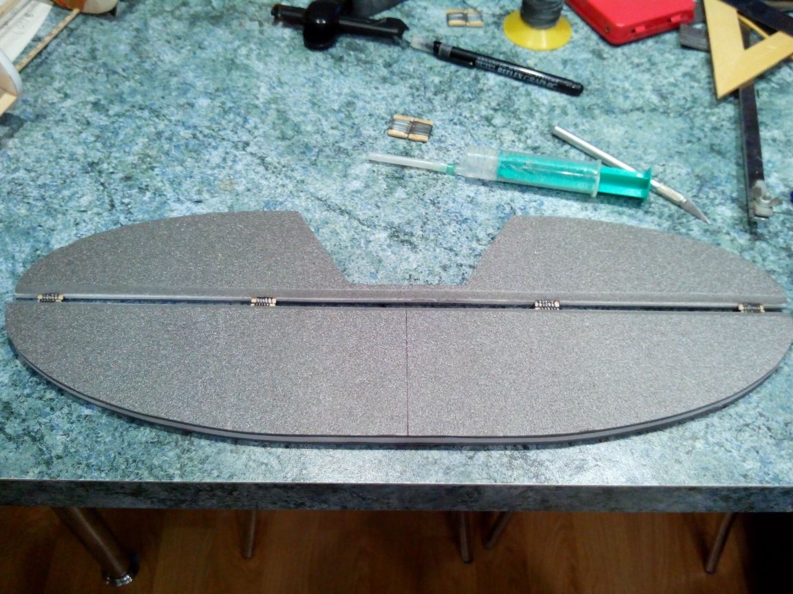
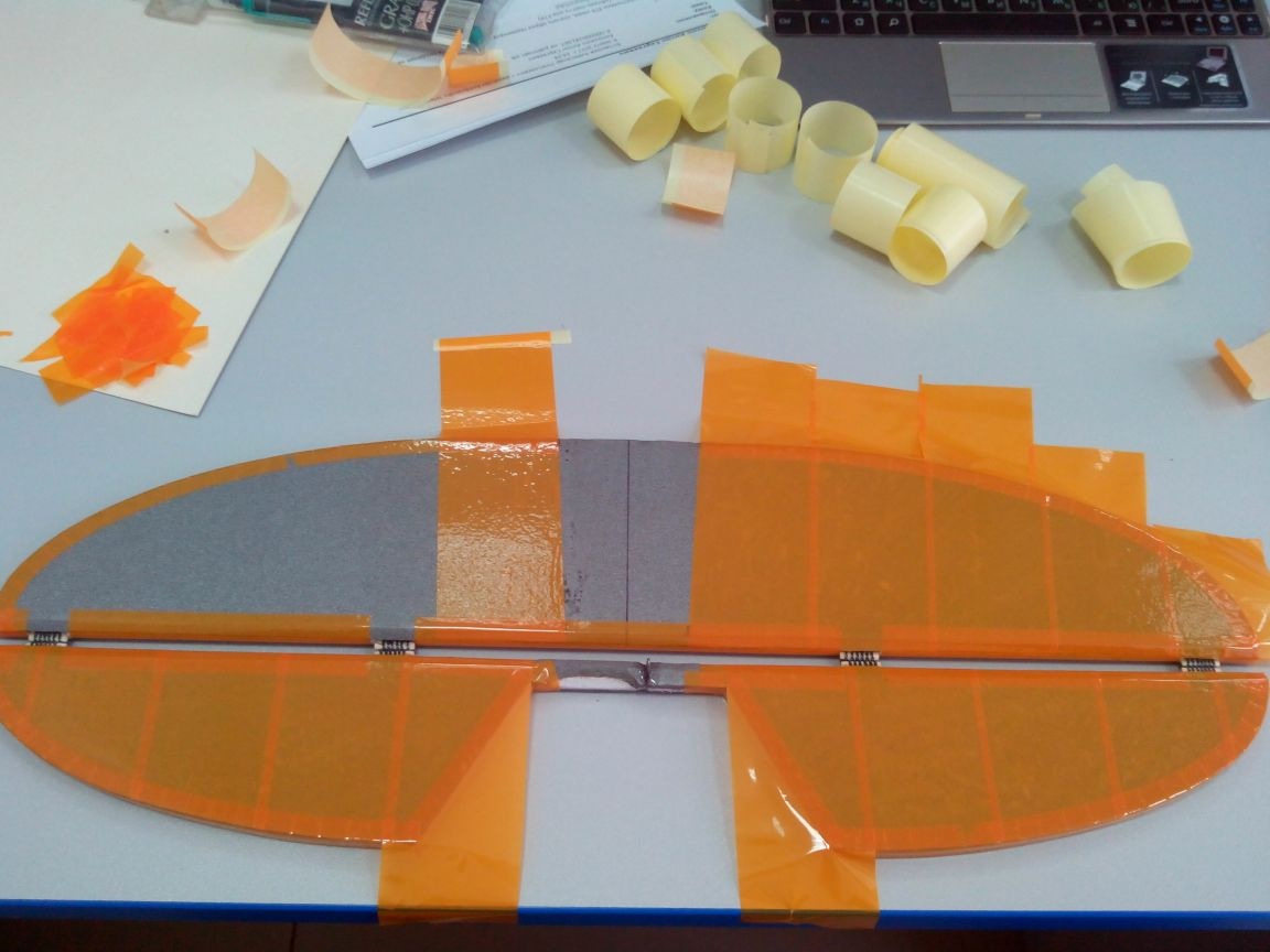
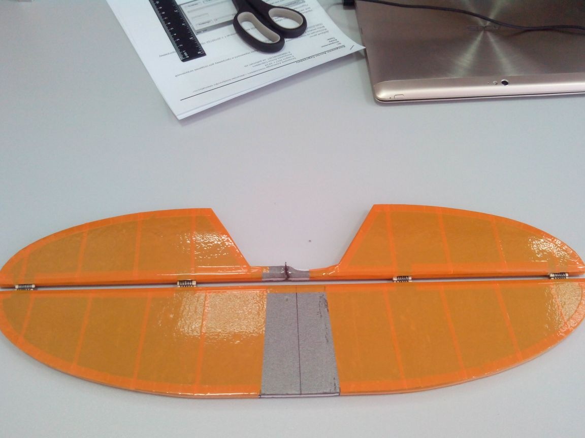
Step 4. Production of the tail
Cut from the depressor and ceilings according to the patterns of the stabilizer and elevator.
And we glue bamboo sticks into them (you can bend them over the stove).
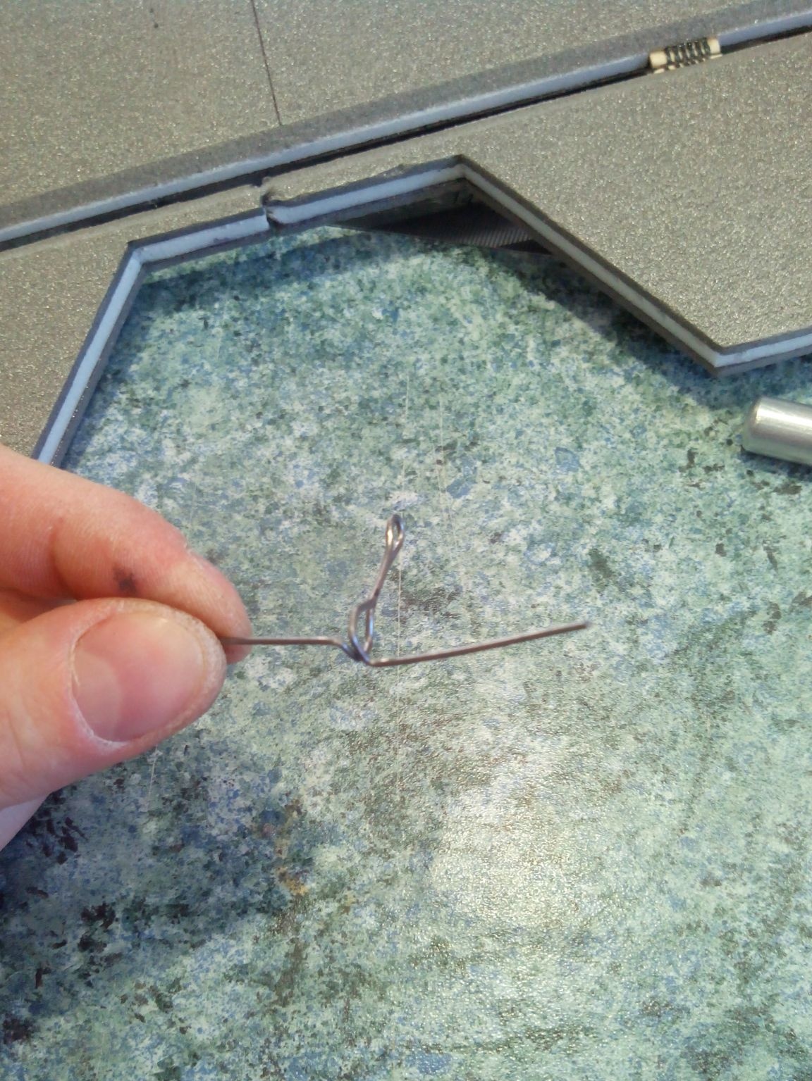
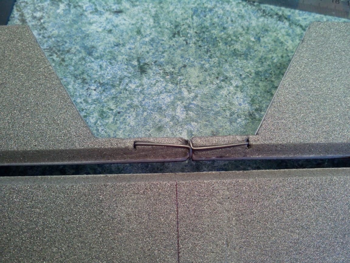
We make loops according to the most proven method - pieces of a ruler and thread.
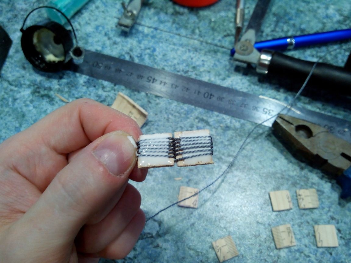
Glue loops on epoxy glue.
Stabilizer ready
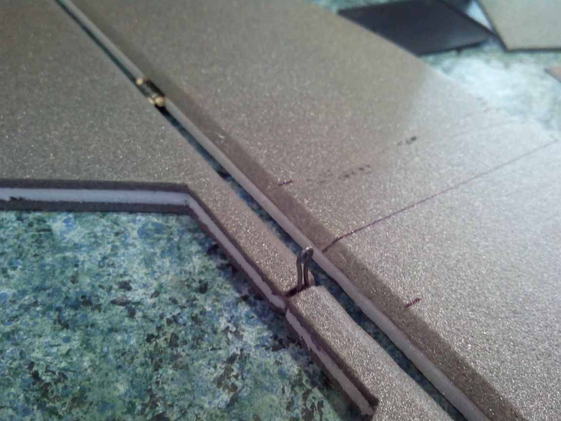
From the wire we bend the boar of the elevator.
Glue it on epoxy.
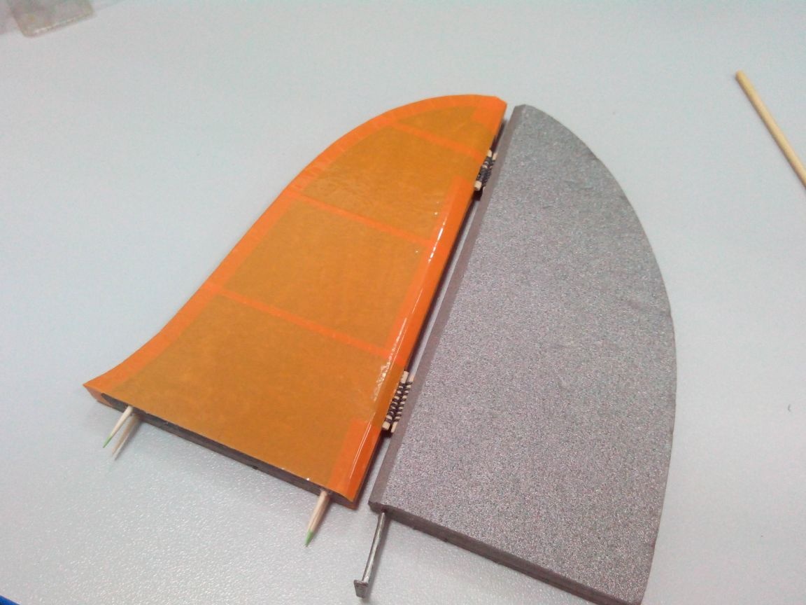
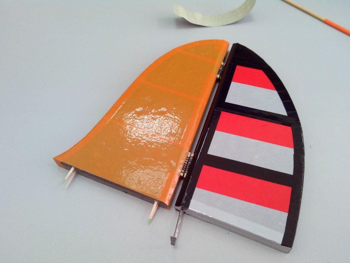
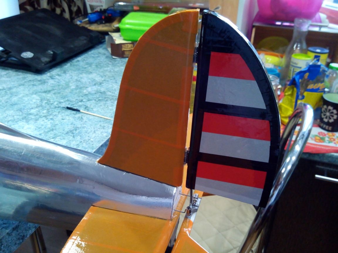
Similarly, we make a keel and rudder, only immediately in the process of gluing the halves we add between them a boar from a steel bar, which is flattened and drilled at one end.
For a more reliable fixation and fitting of the keel, we glue the toothpicks into it.
We glue the stabilizer with tape.
We glue the keel and rudder.
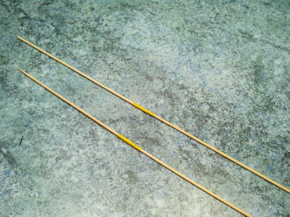
Drafts of bamboo sticks. If there is not enough length, glue “on the mustache”. At the ends of the bamboo with thread with glue - pieces of steel wire.
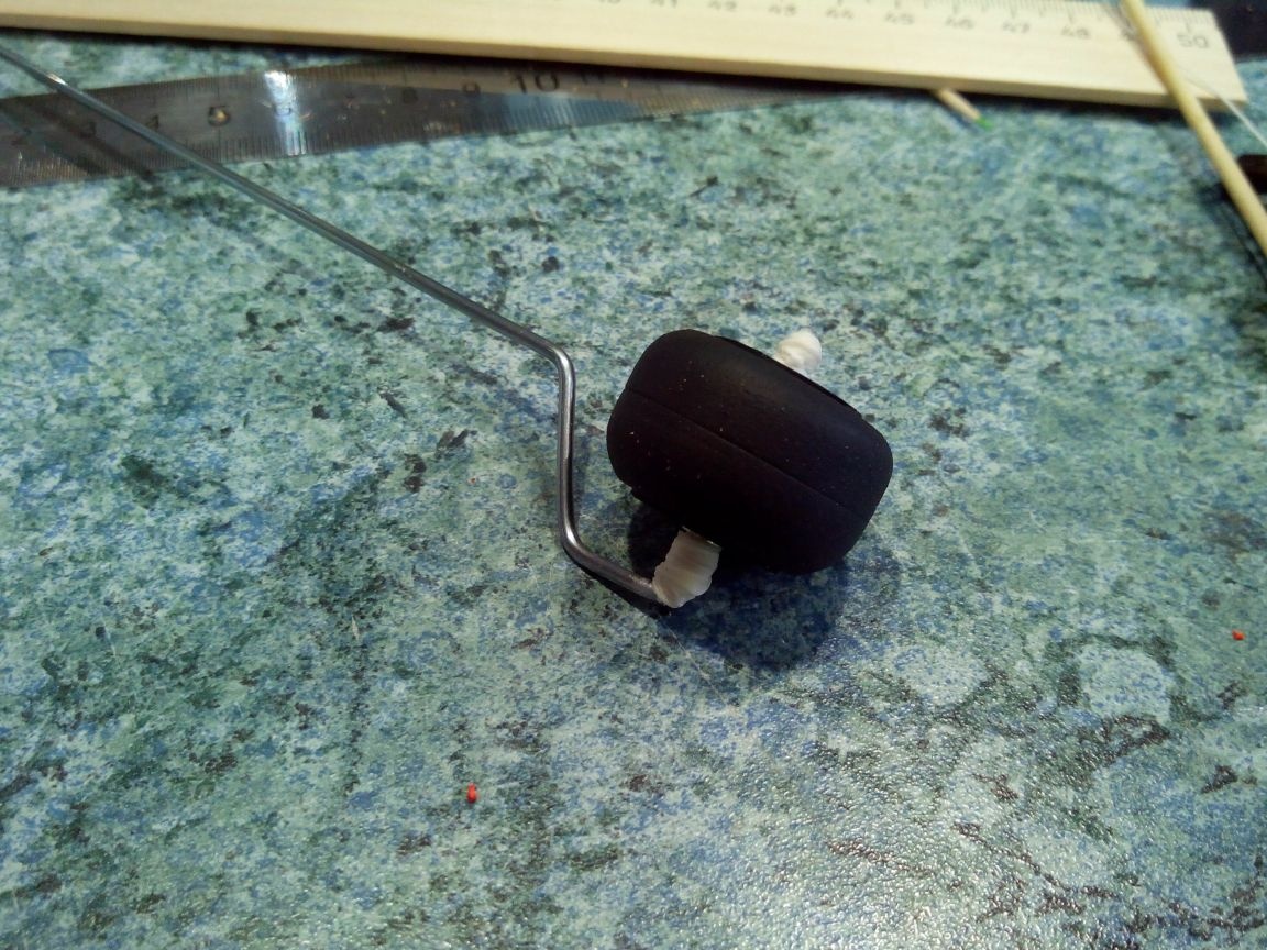
Step 5. Making the chassis
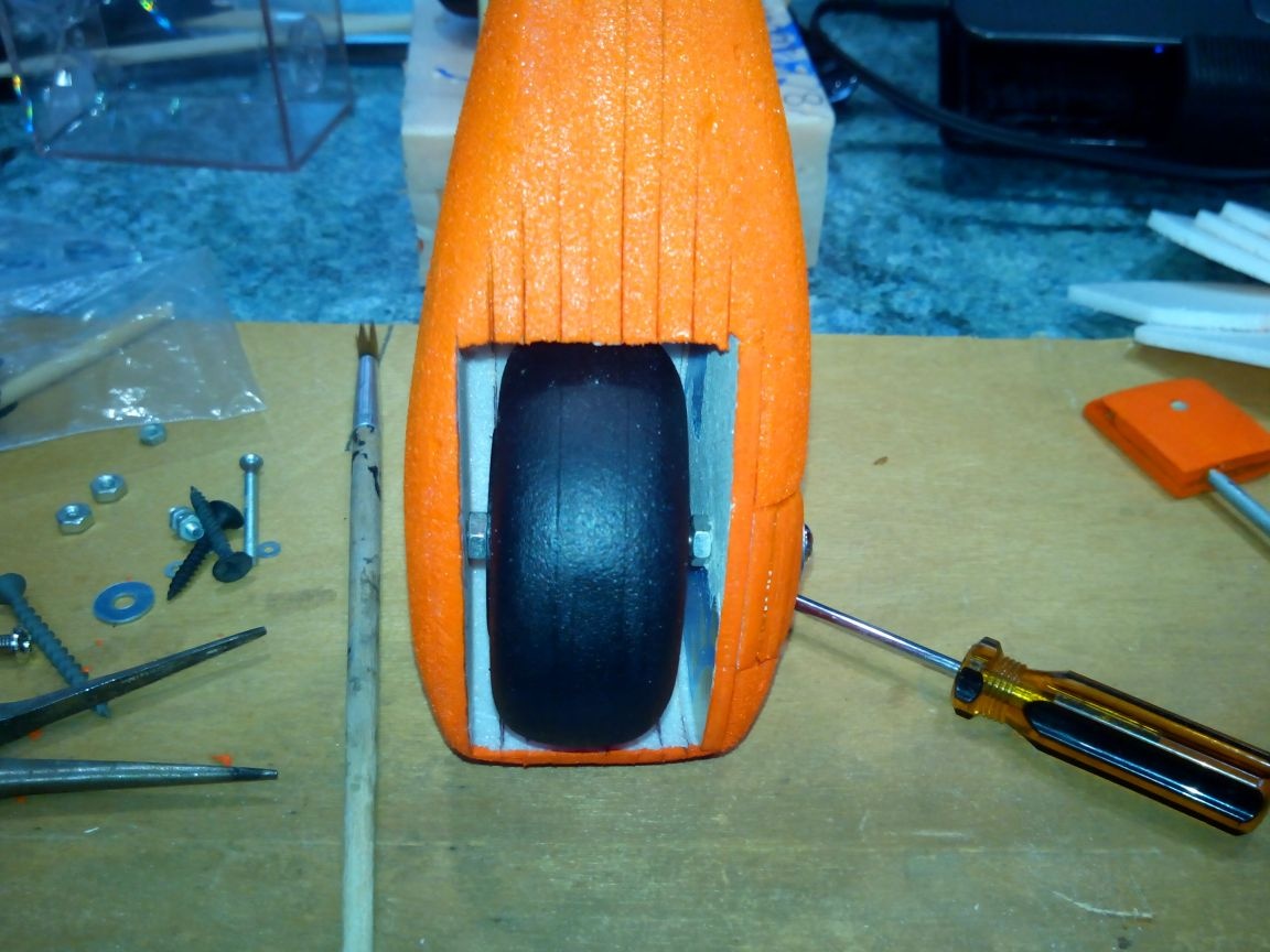
About the manufacture of wheels for aircraft models there is an article: Homemade wheels and chassis for aircraft models
In addition, there was another article about the manufacture of fairings: Fairings for aircraft models
There is nothing fundamentally new on this model; everything repeats those articles completely.
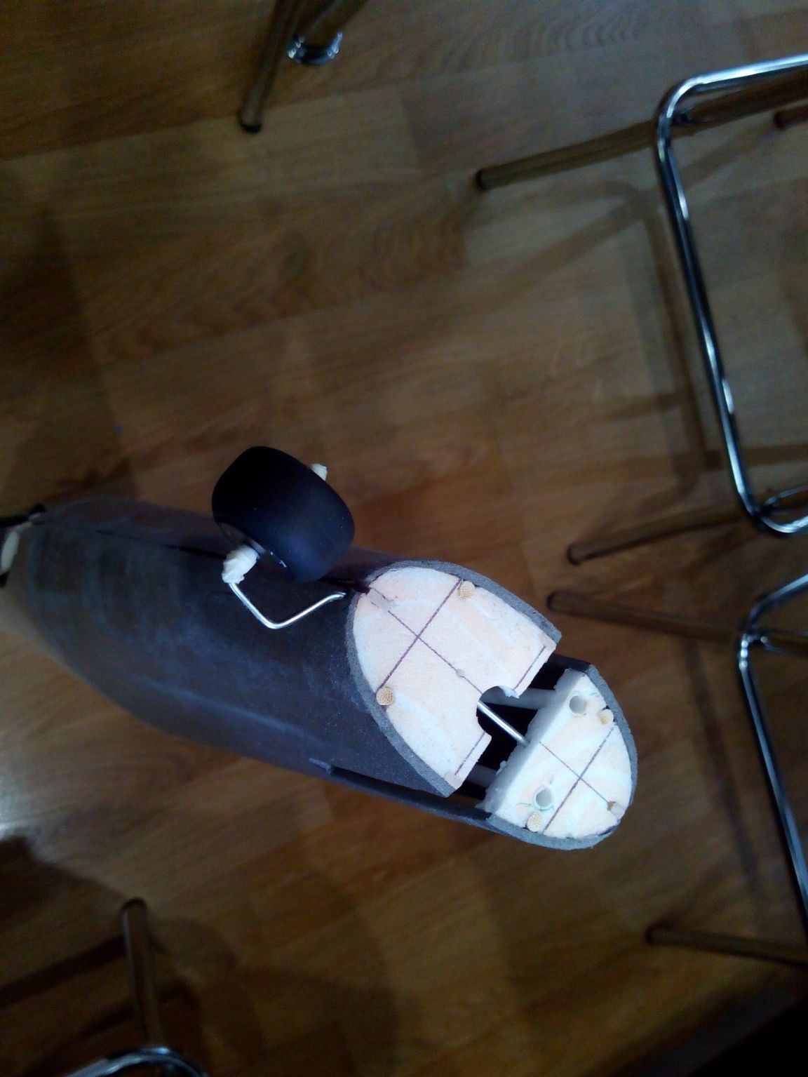
The rear chassis is also made under those articles and will not be turning.
Step 5. Build the model and the last details
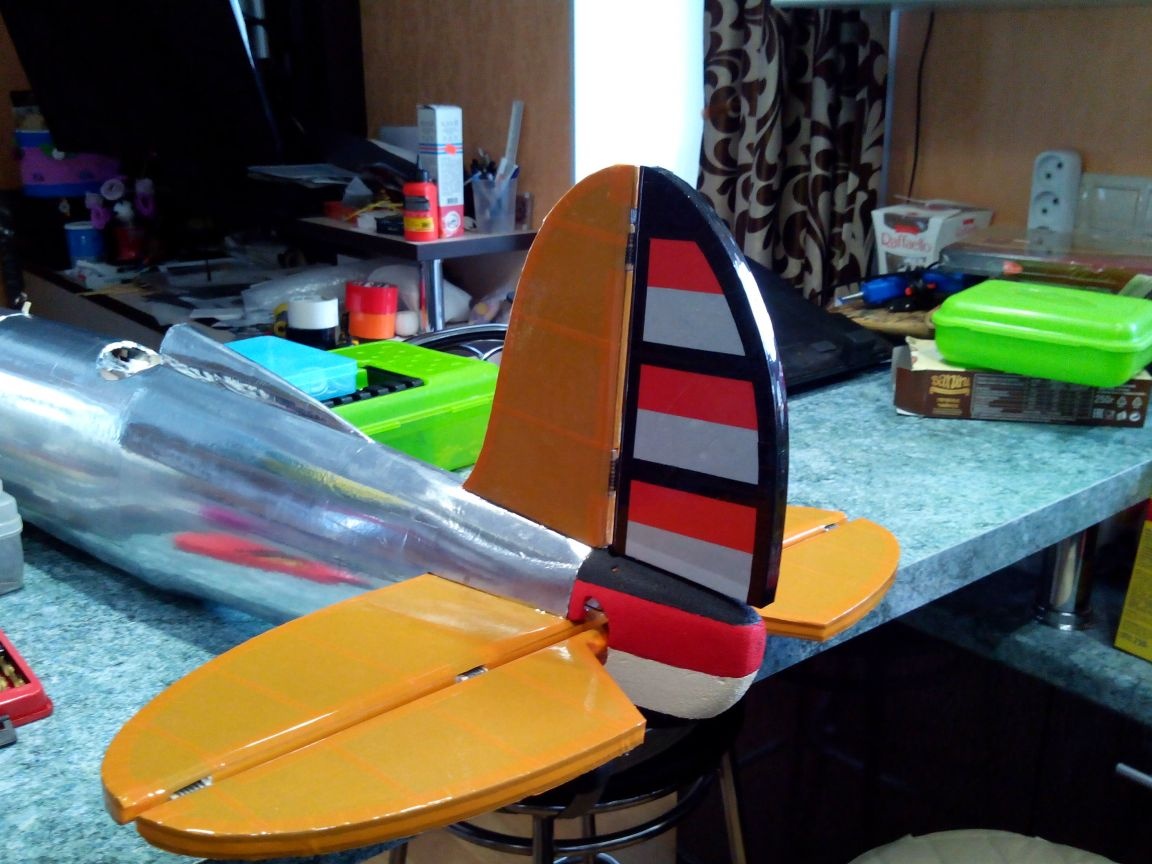
Before gluing the tail unit, we fix the tail rods with clamps in the rockers of the servos. Then glue the stabilizer.
After the glue dries (if earlier, you can accidentally skew the stabilizer) we glue the keel.
We are waiting for the glue to dry, then we fix the traction in the boars of the elevator and rudder.
Now you can stick the tail cone.
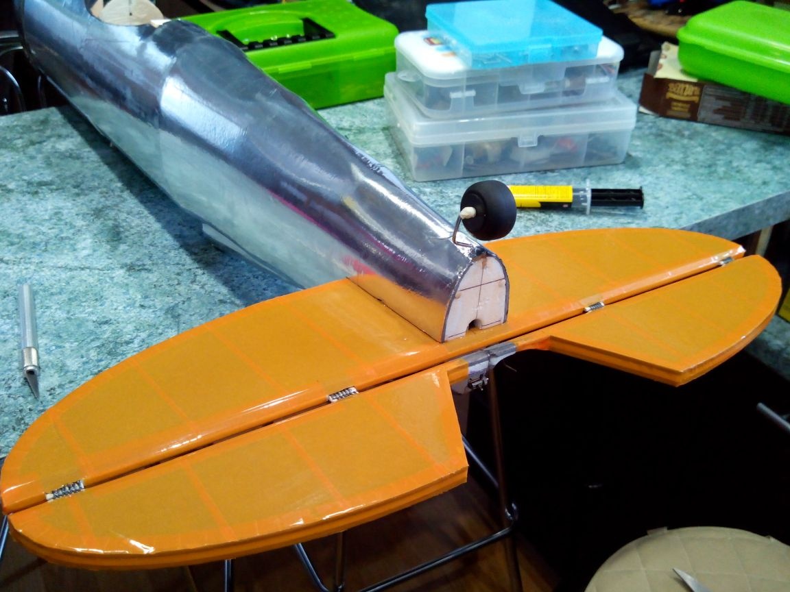
We fasten the wing to the fuselage.
Glue decorations to the ends of the wing.
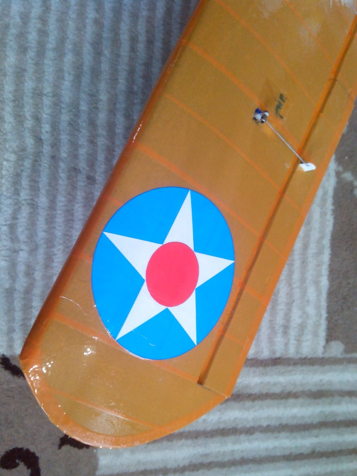
Glue the number on the sides of the fuselage (we print all the decorations on the printer).
We put the electronics inside.
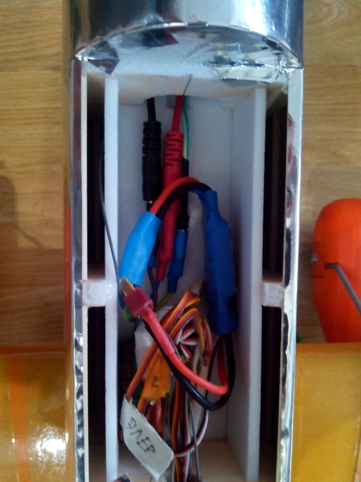
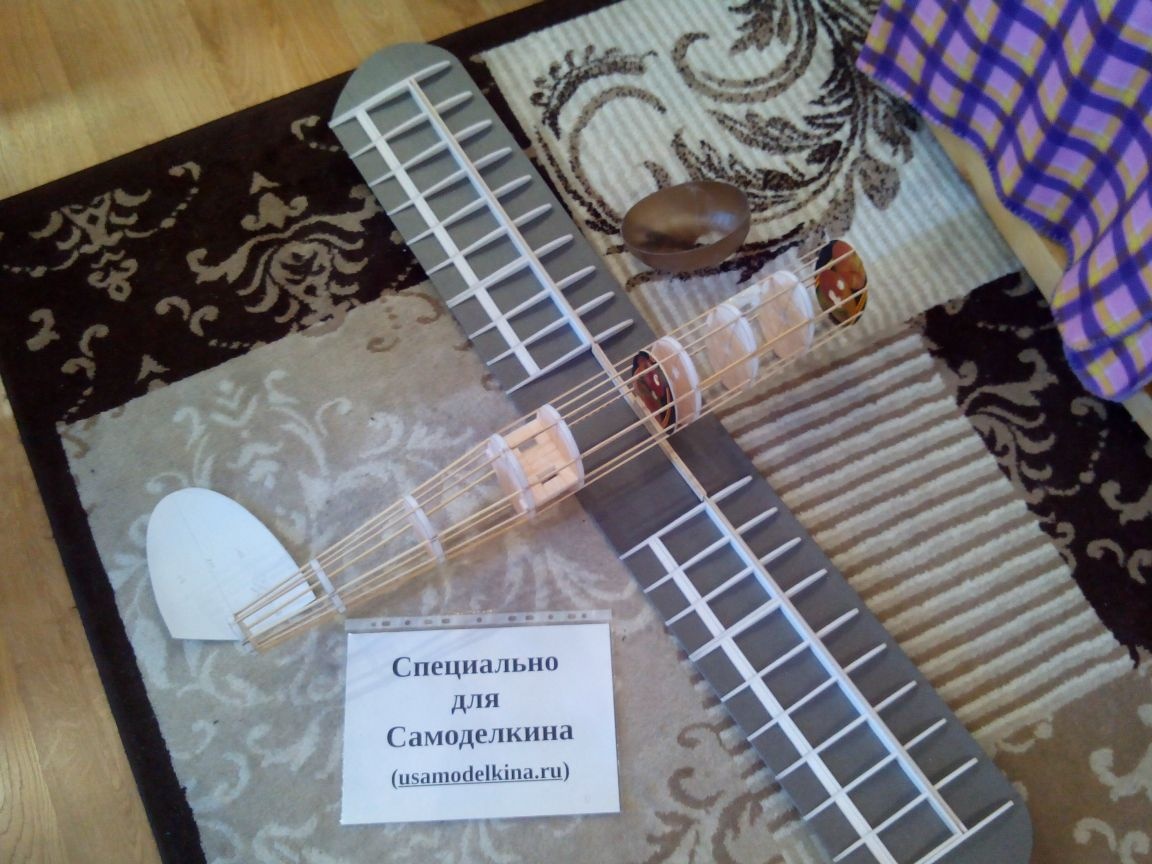
Close the lid. Everything, the model is ready!
Video of flyby and flight.
It was windy on the street, which greatly interfered, but with several attempts and adjustments we achieved a stable flight.