Our Earth is full of energy, if people could learn how to convert it all into electric current, as an example, mankind would never need oil, gas, or coal ... Any oscillations can be turned into a current, whether it be vibrations of air, water, trees and other things, not to mention solar energy. We are also surrounded by such a form of energy as radio waves, thousands of radio stations emit them, satellites, even the Earth radiates radio waves of a certain frequency, because, in fact, it is one huge magnet.
In this article we will look at how you can convert these same radio waves into an electric current. If you collect a lot of such plants, you can charge the batteries or use free energy for any other purpose.
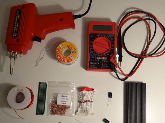
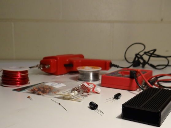
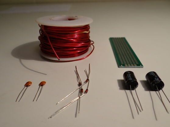
Materials and tools for homemade:
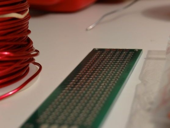
- printed circuit board;
- copper wire 10-18;
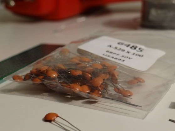
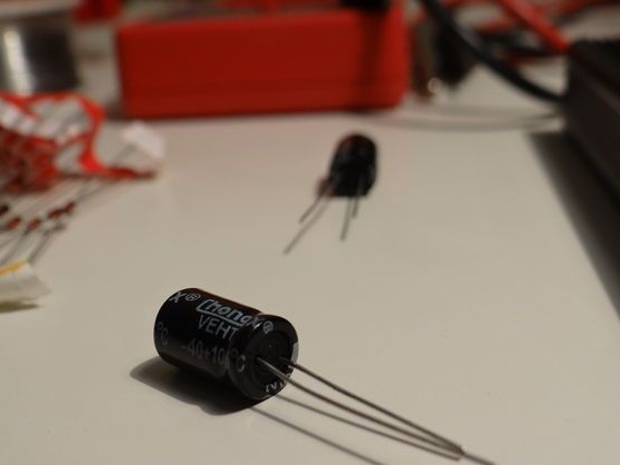
- ceramic and electrolytic capacitors;
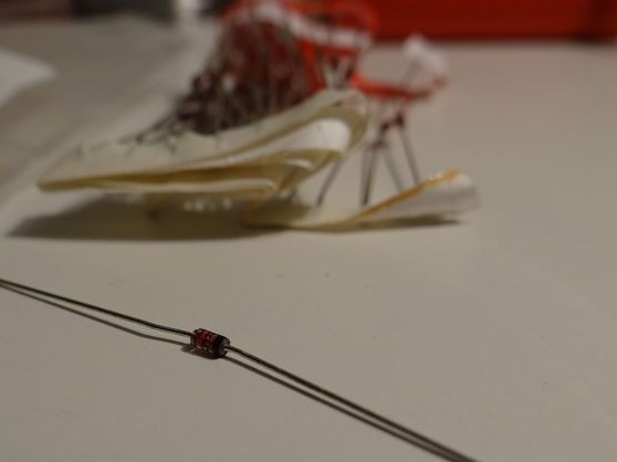
- diodes;
- materials for the manufacture of the antenna (copper wire);
- soldering iron;
- multimeter;
- preferably an oscilloscope.
Homemade manufacturing process:
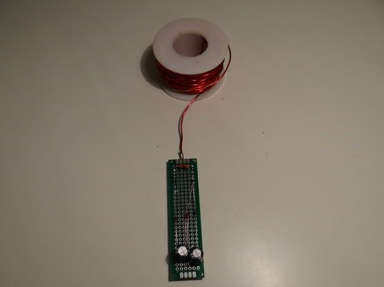
Step one. Homemade Foundation
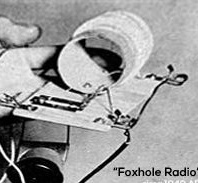
An interesting fact is that crystal receivers, which we have known since the 30s, can operate without any input voltage. They make a sound only due to the energy that is generated from the signal, although the sound there is very weak, but this is an indicator.

Thanks to modern technology, the signal can be significantly amplified, here germanium diodes come in to help, which have very high-quality crystals. Thanks to them, you can take a wide range of frequencies, and not adapt to only one frequency, but all this is energy.
Step Two Create a scheme
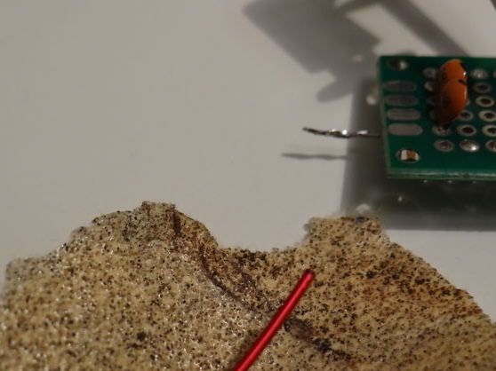
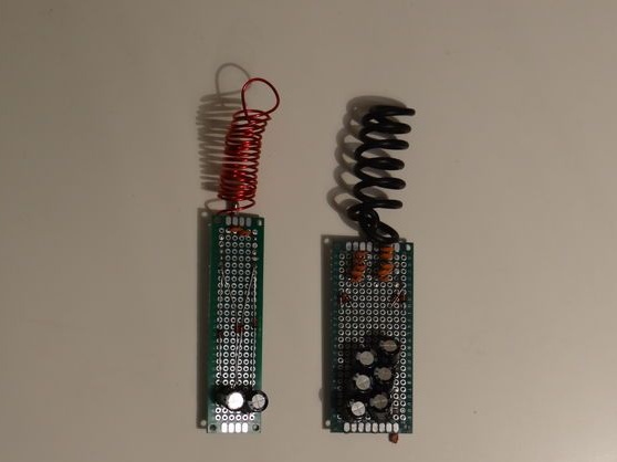
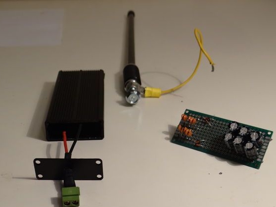
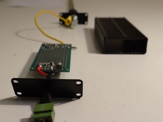
The layout of the device is quite simple, it was created here solely to confirm the experiment. The circuit consists of an antenna, it receives a signal, which is then fed to two ceramic capacitors connected in parallel. As a result of this, the signal is already converted into a current with different potentials, that is, with a positive and negative output.

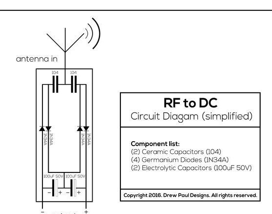
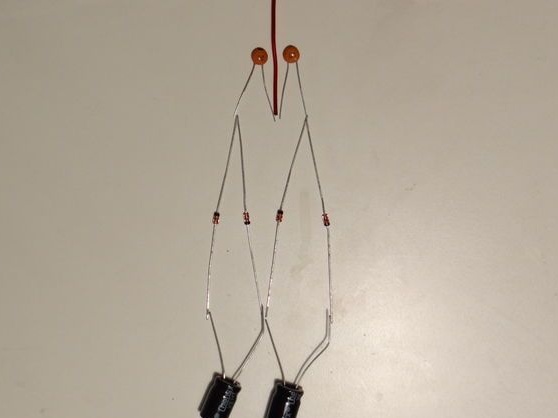
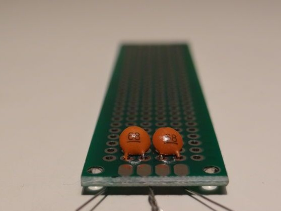
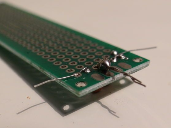
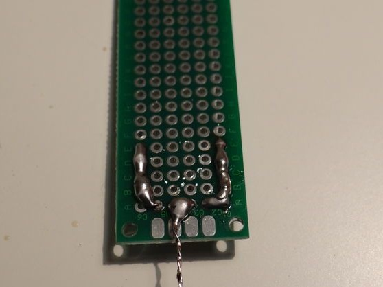
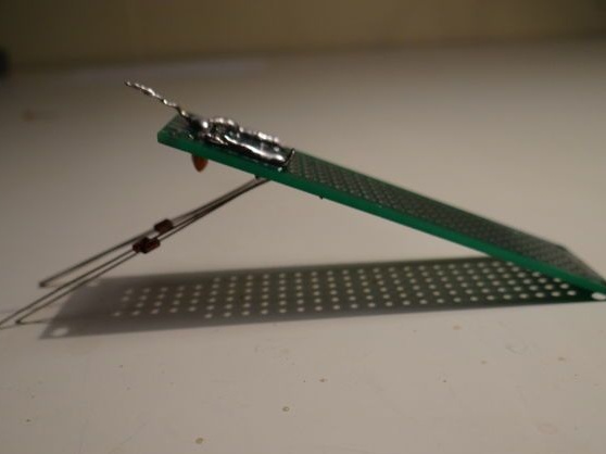
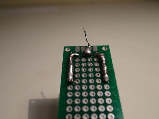
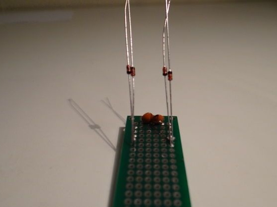
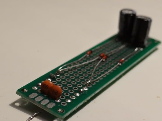
Further, diodes are connected to these two capacitors, they will be needed in order to turn alternating current into direct current. Well, now, with the help of this very “constant” electric current, it is possible to charge electrolytic capacitors. First, the entire circuitry can simply be connected by wires, and then soldered to the circuit board.
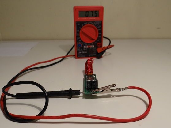
Step Three Verification and optimization of work
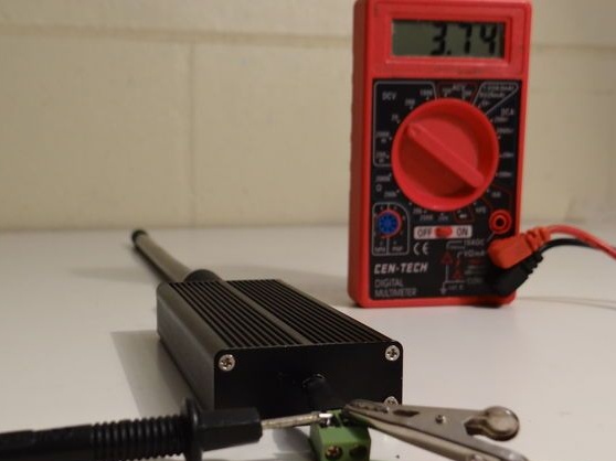
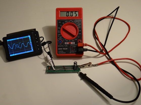
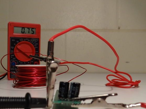
To test the device, the author used an oscilloscope and a multimeter. Immediately after connecting the multimeter, you can see the wave-like voltage in the region of 10-100 mV. If this is not observed, you need to check the quality of the connection and go out into the open.
In order to thoroughly see how everything works, you will need an oscilloscope.
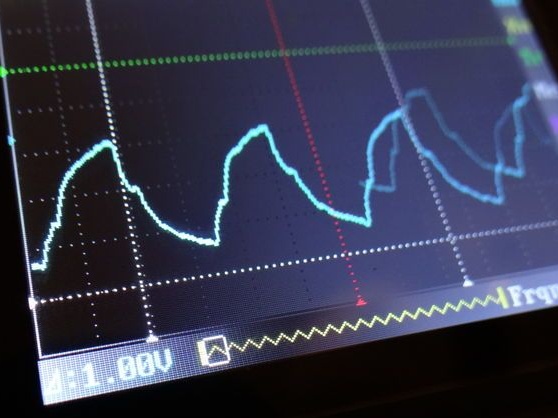
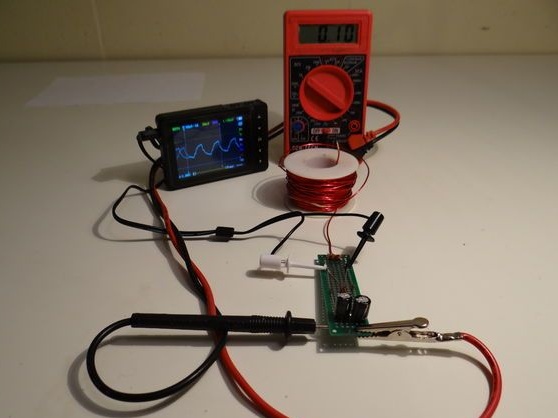
First, the author connects the oscilloscope to the terminals of ceramic capacitors, while one can observe how the signal is captured from the environment. By connecting after the diodes, you can see the alternating current, but after the electrolytic capacitors, the current is already direct.
To optimize the input impedance, you can use all the same ceramic capacitors that are connected in parallel with the existing ones.
As for the capacitance, if necessary, it can also be increased by installing additional electrolytic capacitors.
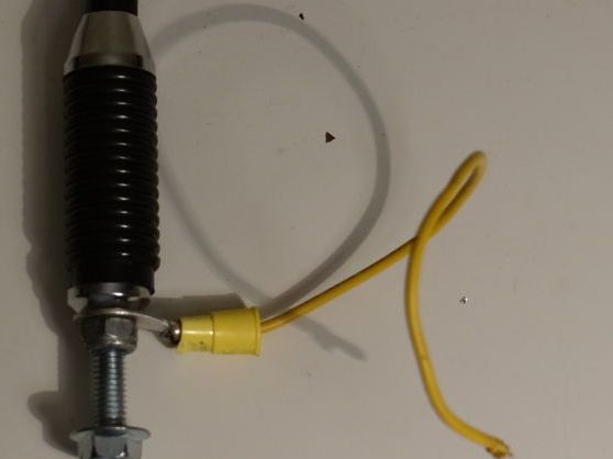
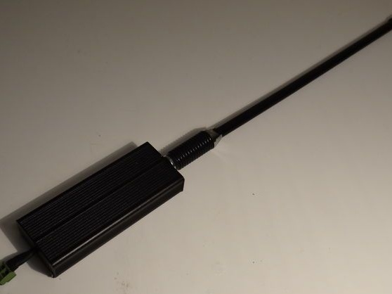
To optimize the antenna, you will need a copper wire, with it you can lengthen the existing purchased antenna, thereby raising it as high as possible.
If you need to increase the current, then you need to create several such devices and connect in parallel. And if you need high voltage, then homemade products are connected in series. In general, there is no limit to perfection.
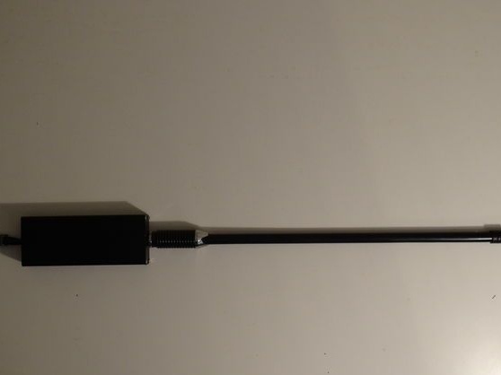
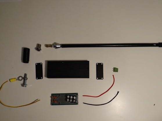
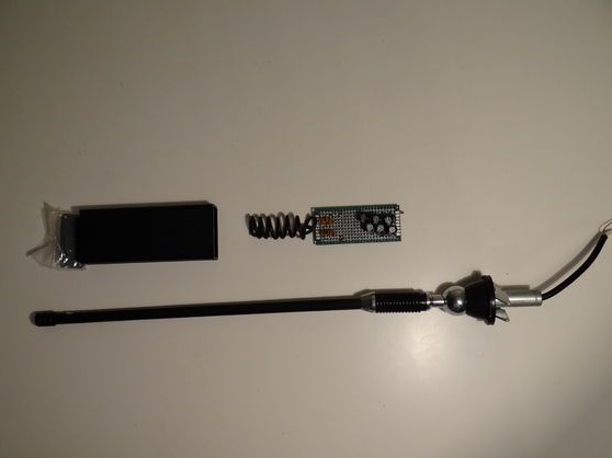
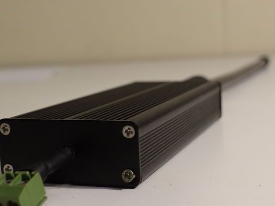
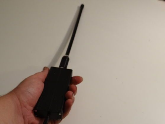
Step Four Housing and antenna
The antenna can be any, powerful or weak, miniature or large fixed. In any case, it is connected as indicated in the diagram. The input signal will go to the metal case, that is, to ground.
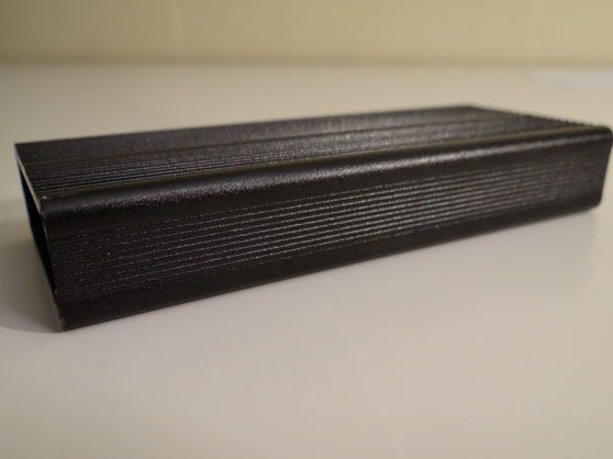
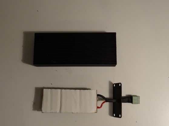
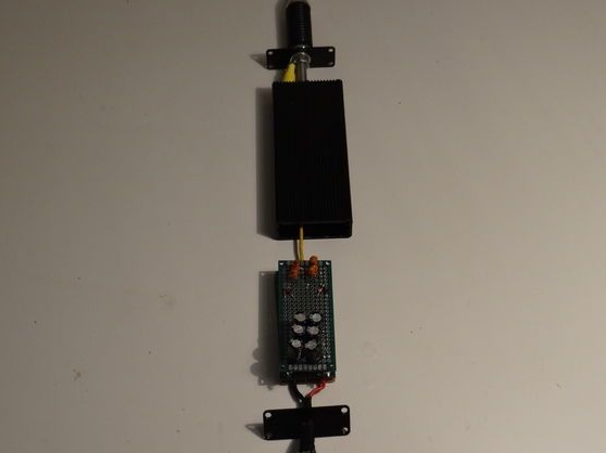
The author collects everything neatly in a plastic case. It is necessary to make a hole for the antenna, as well as going out for the terminals to which you can connect to test the homemade.
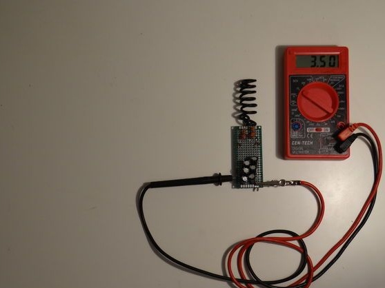
The final stage. Homemade testing
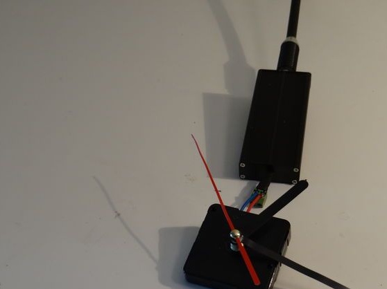
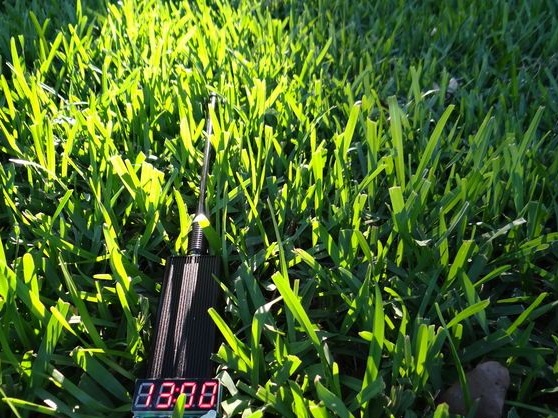
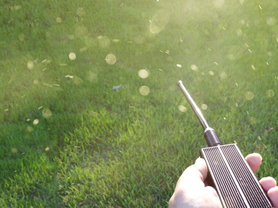
Now the crystal receiver-generator is completely ready and can be tested. The author made a portable version of the receiver to simply show how it works and works in principle. Using this method, you can create a more powerful installation or several, while receiving a good amount of energy for domestic needs.
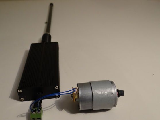
If you believe the author, then from the generated energy he was able to start a quartz watch that consumes little current. The chronograph with integrated circuits and an LCD display was also able to work, and a small motor was also launched.
As a result, we can say that this project is quite simple and reliable, and at the same time very interesting.