

This article describes in detail the process of connecting Turnigy TGY-i6 radio control equipment to a computer and its configuration for use in flight simulators.
Materials:
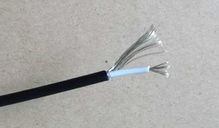
- Single core shielded wire
- 10 kOhm resistor
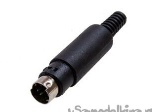
- S-Video plug
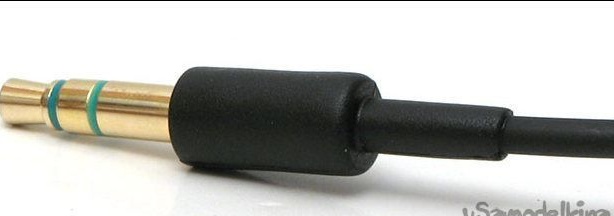
- Mono-jack 3.5 mm "minijack"
- Heat Shrink Tubing
Instruments:
- Knife
- soldering iron
- solder
- pliers
- Lighter
Step 1. A little theory
In order to connect the equipment to the computer, special USB cords are used, which either cost money or cost a lot of money when they are sold complete with an flight simulator. But there is a simpler and less expensive way - to connect the equipment through the microphone input and use the equipment in a free simulator Fms.
In radio control equipment, the encoded signal of the standard PPM (analog) or PCM (digital) is used. Using special programs and a cable that is easy to manufacture, you can decode the signal and “transmit” it to the computer through the microphone input.
These programs are called: PPJoy and SmartPropoPlus.
PPJoy - This is essentially a virtual joystick driver that emulates a standard joystick in Windows and receives data from.
SmartPropoPlus - This is a program that takes the microphone input data of the sound card, decodes the signal and transfers it to.
The site has the latest versions of these programs.
For initial training or acquaintance with simulators, you can take any available equipment, the main thing is that it has the ability to shoot a PPM / PCM signal.
Let's turn to the hardware Turnigy TGY-i6.
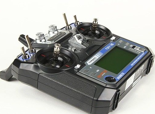
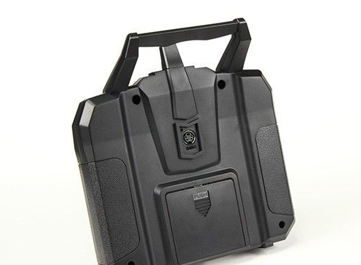
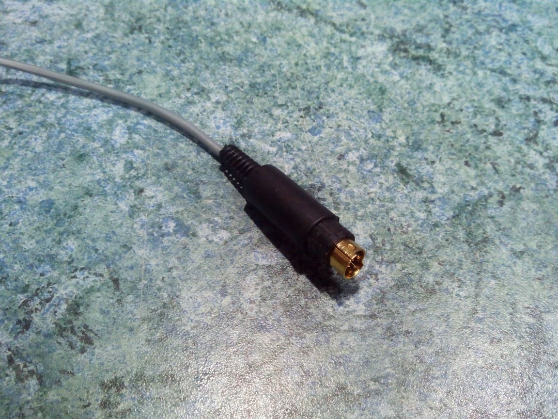
In this equipment, there is an S-Video coaching connector on the back wall.
The PPM signal leaves the pin indicated in the diagram. red arrow. Green the arrow indicates "earth."
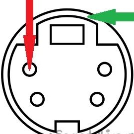
It is necessary to connect the PPM contact through a 10 kΩ resistor to the central pin of the 3.5 mm connector. A minus, respectively, with a minus. However, here is a diagram.
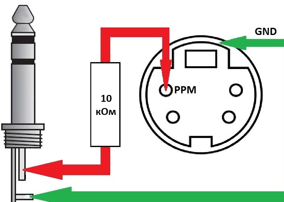
You can use a stereo connector for the cord, but to avoid unnecessary interference, it’s better to remake the connector from the computer side to mono. In addition, you can solder the cable without a resistor, but there is a risk of burning a sound card or a coaching connector in the equipment, and therefore it is better not to risk it.
Step 2. Solder the cable
We take a single-core shielded cable of the required length. I immediately took 3 meters, because the computer is far in the corner and connected to the TV.Looking ahead, I’ll inform you that it works very well, the length of the wire did not affect the signal quality.
We cut off the 3.5 mm jack from the old microphone (or buy).
We find in the bins (or again buy) the S-Video plug.
We buy or solder a 10kOhm resistor from some board.
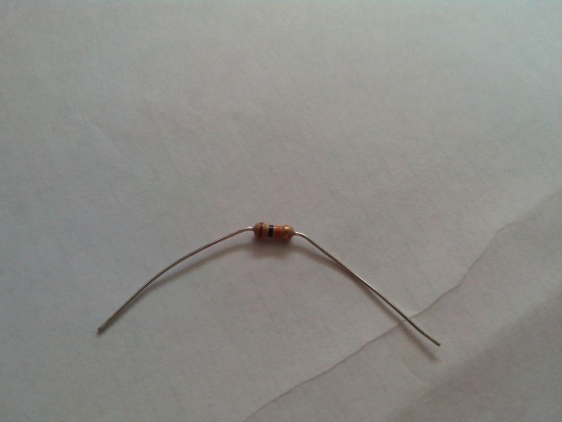
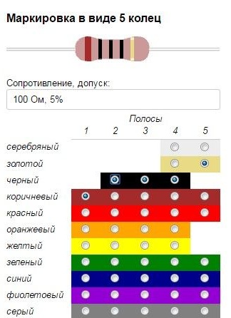
Yes, if the resistor is evaporated from the trash, then I recommend the site. The color coding of the resistor will make it easier to determine its resistance. Just put the flags on the colored stripes and look at the resistor rating on top (see screenshot).
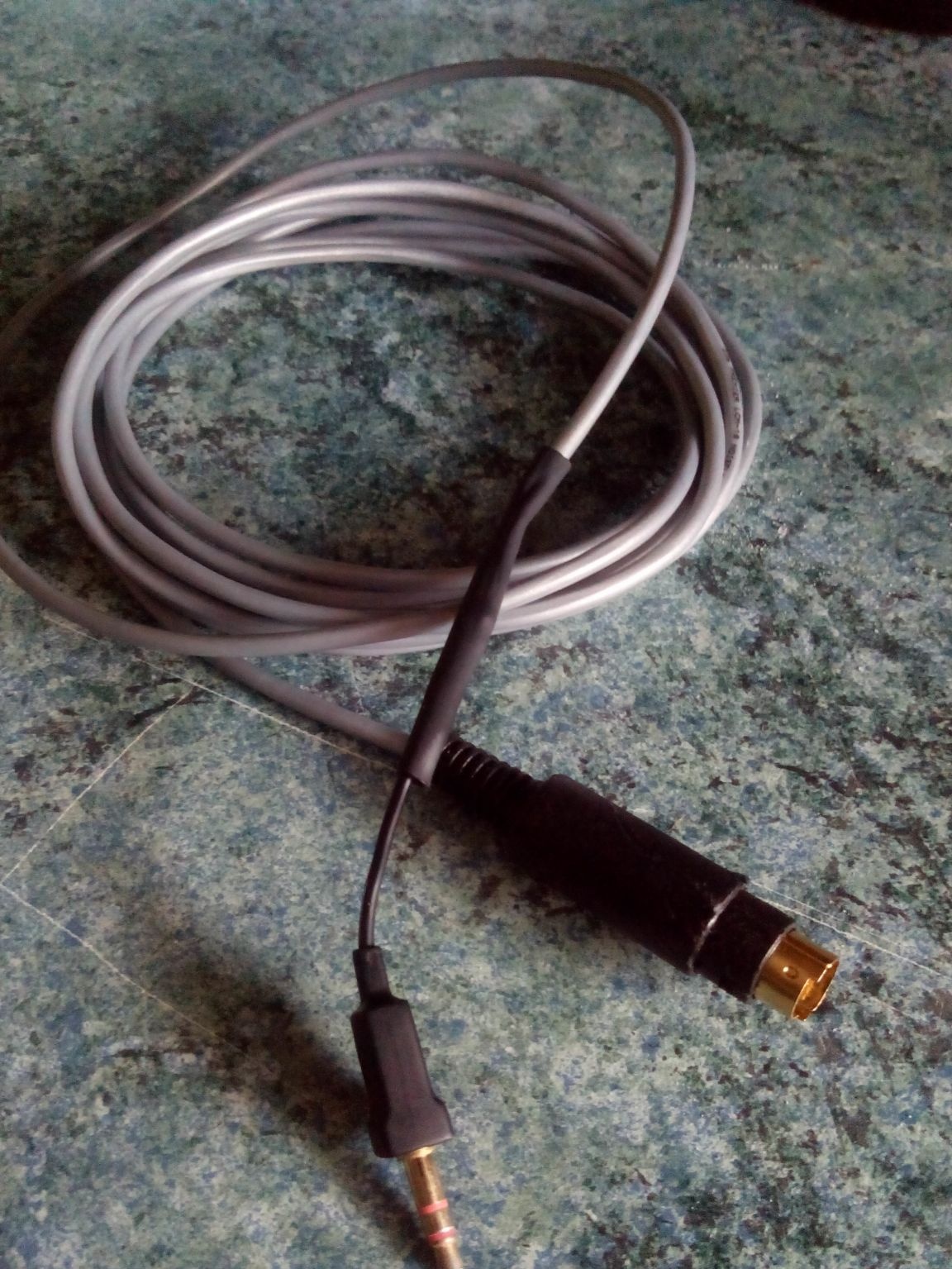
We clean and tin the contacts of the wire, solder the resistor, close the heat-shrink tubing and solder the 3.5 mm audio jack.
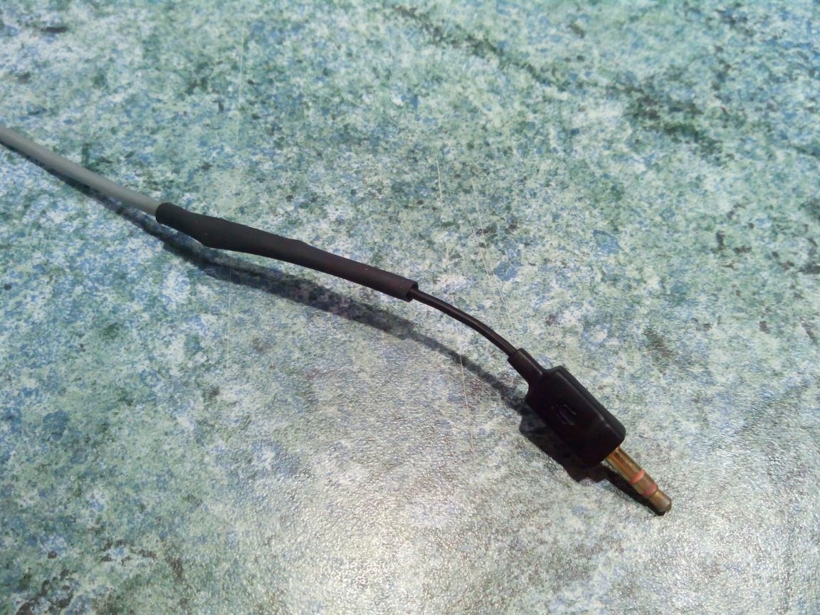
We disassemble the S-Video plug, solder the central wire to the desired pin, and “minus” to the case.
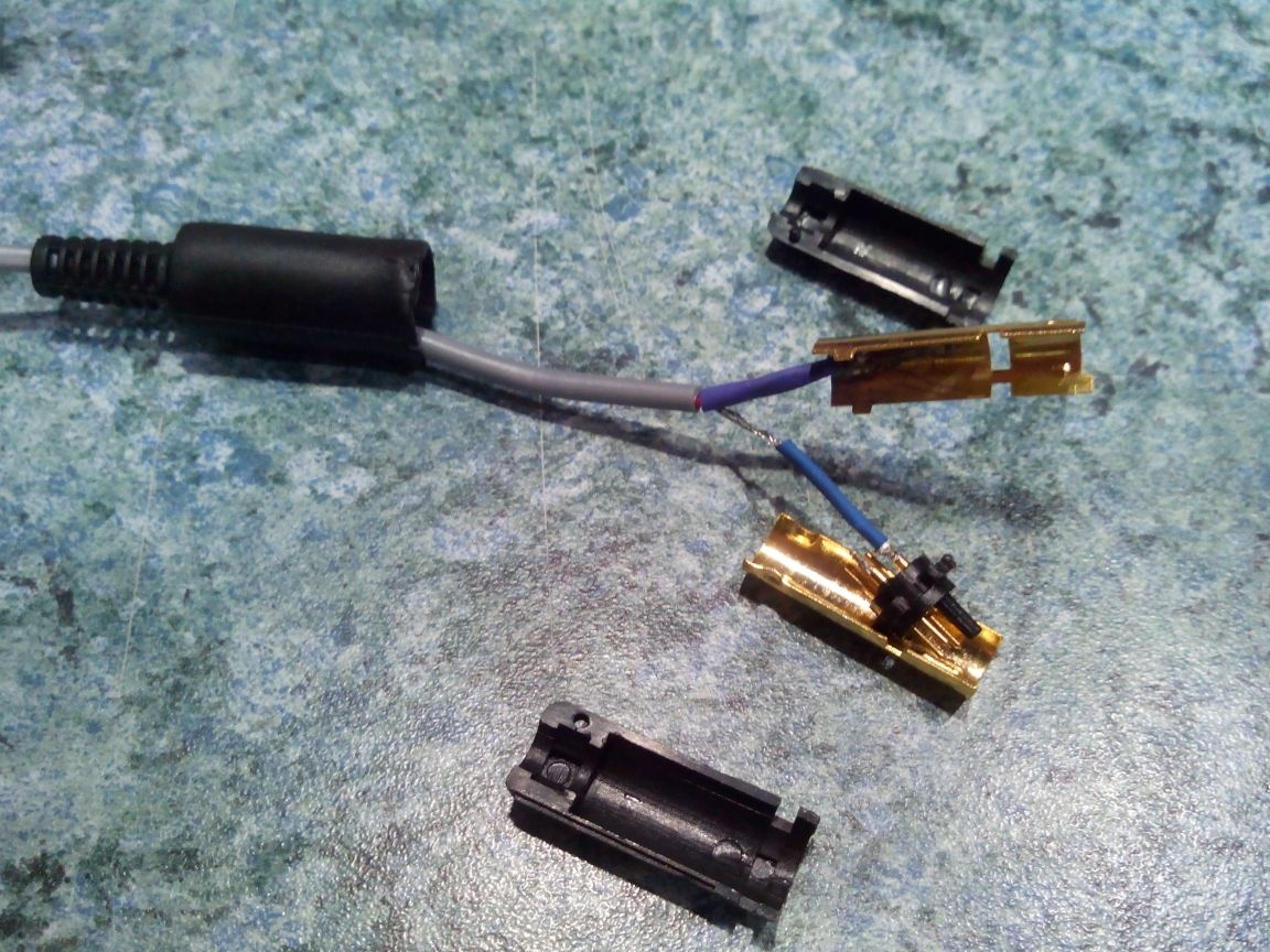
We assemble the plug.
The wire is ready, you can proceed to the installation and configuration of programs and.
Step 3. Installing programs
I collected both programs and the FMS simulator in one archive.
Since now it is becoming more and more difficult to meet Windows XP (and besides, it will not have the difficulties described below), I will immediately proceed to the installation procedure in the Windows 7 operating system.
PPJoy - This is a driver, but it does not have a certified digital signature (this is expensive for the developer). Windows XP normally refers to the installation of unsigned drivers, but Vista and 7 initially do not allow them to be installed.
To install, you must first disable the digital signature verification of drivers in Windows. The Internet is full of information on how to do this.
In Windows 7, I chose the simplest option:
- Click on the keyboard - the window ""
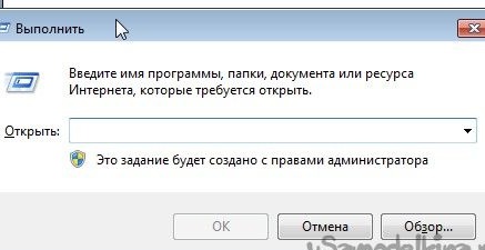
- Copy and paste the line there:
- push
- Press the keyboard again
- Copy and paste the line:
- push
- Reboot the computer
If everything was done correctly, then in the lower right corner of the desktop there will be an inscription:
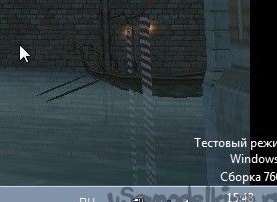
You can start installation PPJoy.
After running the exe-file on a 64-bit OS, a window pops up:
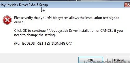
Click and continue the installation.
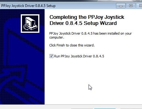
After the installation is complete, run.
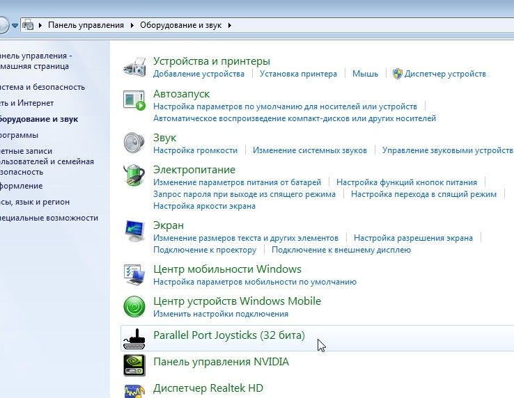
In the future, it can be launched through the control panel.
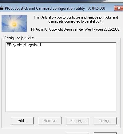
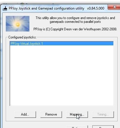
After launch, the list of virtual joysticks will be. If this window is empty - add a new joystick with the "" button and press the "" button.
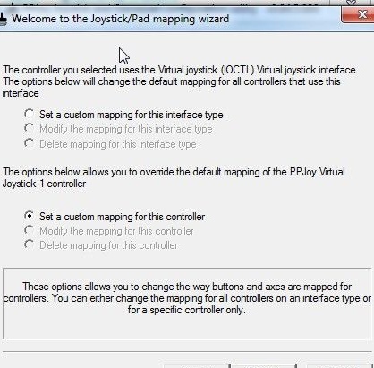
We do further actions as in the screenshots
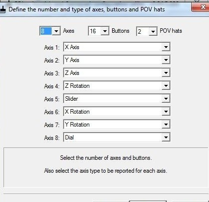
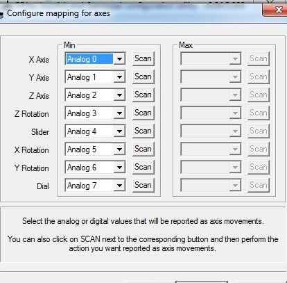
And press the button ""
Now install SmartPropoPlus.
After running the exe file, the installation program will offer two options:
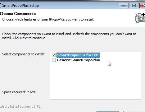
1. For use with the free FMS simulator.
2. For use in other simulators (for example, AeroFly).
We select the desired option and install it.
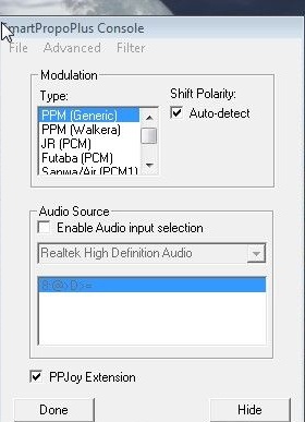
Launch SmartPropoPlus and put a checkmark at the bottom. To minimize the window, press the "" button. The "" button completely closes the program, but for the remote control to work, the program must be running!
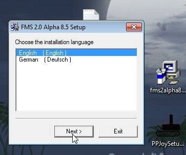
Step 4. Installing the FMS Simulator
Run the file from the archive. Choose the installation language.
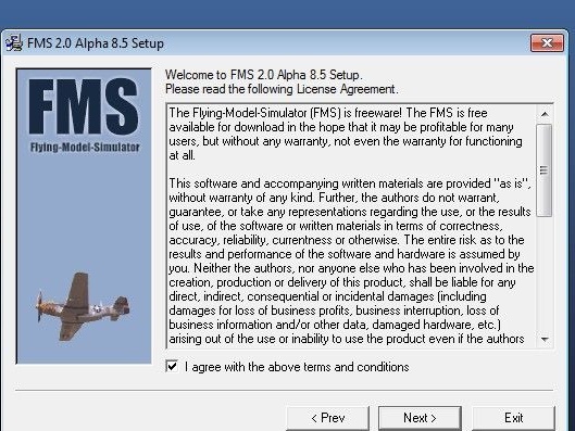
Check the box, agreeing to the license agreement and click ""
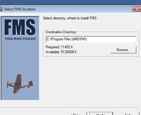
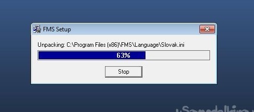
Choose the installation path (the simulator "weighs" a little, you can leave the default path)
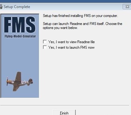
We are waiting for the end of the installation
After installation is complete, click ""
When starting under Windows 7, an error window pops up:
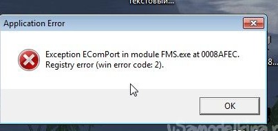
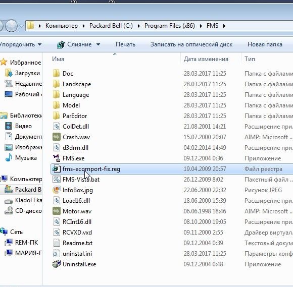
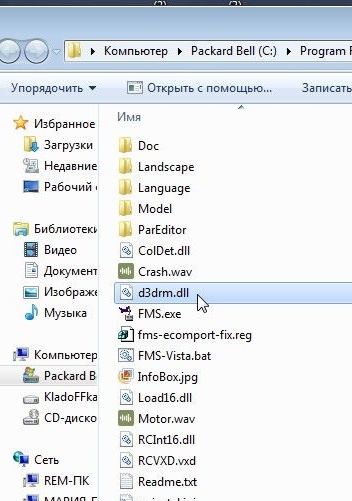
To fix this, go to the folder with the simulator installed
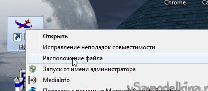
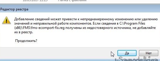
Find the file and double-click it.
Click ""
And ""
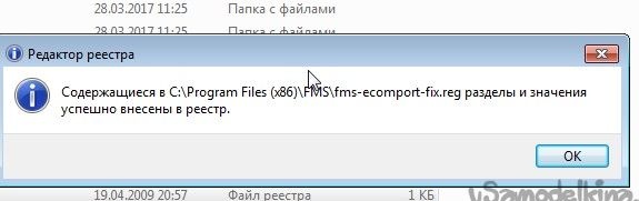
Everything, in the future, the simulator will start without problems.
It happens that the already installed and archived version of the FMS simulator is downloaded on the Internet, and there is no library there.
It can be downloaded from special sites using the search.
Step 5. Hardware setup and calibration
For our remote control to work correctly, it must be calibrated.
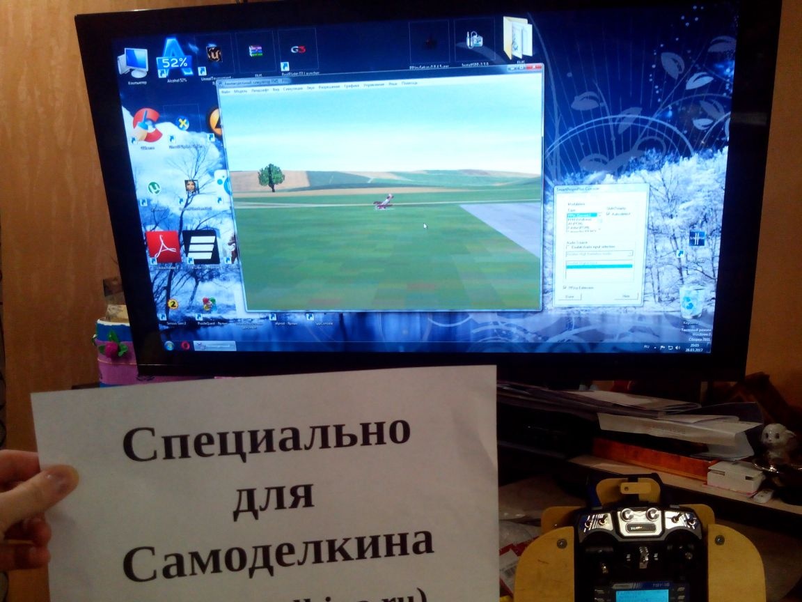
We start and without closing it we launch the simulator.
In the upper panel we find the item "" - ""
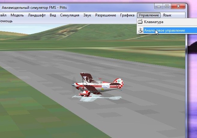
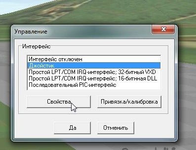
In the "" window that opens, select "" and go to the properties.
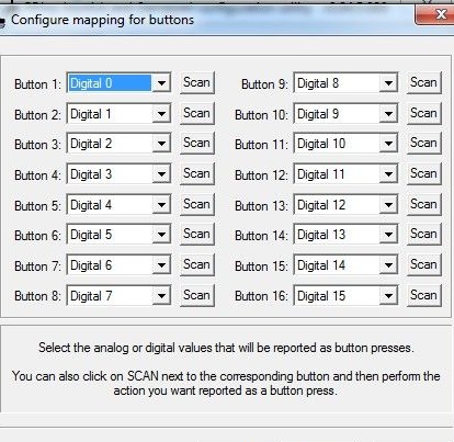
In the "" window we see six columns-channels of our remote control.
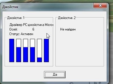
If you see the situation approximately as in the screenshot and the bars change height when you move the sticks on the equipment, then so far everything is going well.
And now very important information for laptop owners!
Since laptops often use very mediocre sound cards, the PPM signal through the microphone input comes with a strong delay and interference (as I understand it, the integrated microphone and the cheapness of the audio card affect this).And therefore, if your columns twitch chaotically and do not react or react for a very long time to stick movements on your laptop during setup and calibration in this window, I have bad news for you. You will have to try connecting the remote control to another laptop or computer, or use a commercially available USB cable. I spent three days, but I couldn’t configure anything on the laptop. But on the computer - the first time.
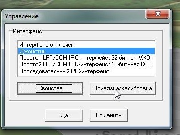
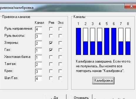
So, if everything is fine, we begin the calibration of the joystick, for which we press the button “Binding / Calibration”
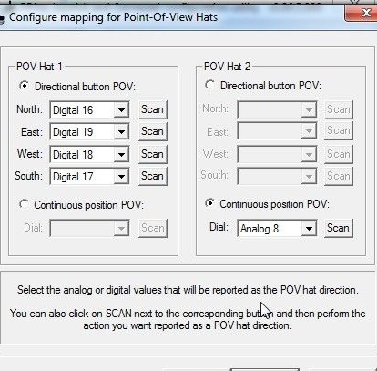
In the left part we see the distribution over the channels and the reverse and exponent settings. On the right side is the “Calibration” button and channel bars.
We move the sticks and look which one gets to which channel, and then on the left side we set the channels for gas, elevator, ailerons and rudder.
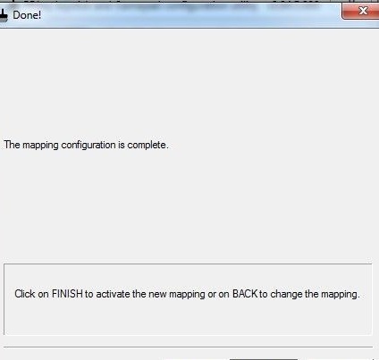
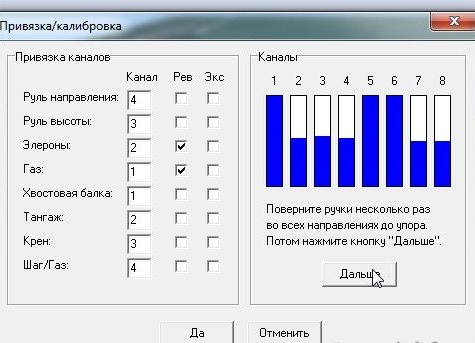
After clicking on the “Calibration” button, we turn all the sticks and “twists” on the remote control several times in all directions, achieving approximately the same picture, and click “Next”:
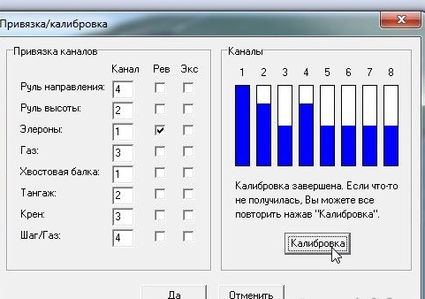
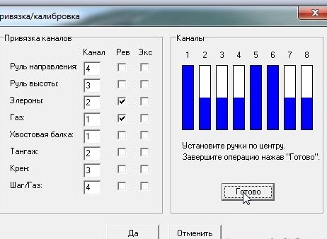
Then click "Finish" and the button "Yes"
If model in the simulator for some reason flies the wrong way, we go back to the calibration and put the necessary check marks for reverse.
Everything, the equipment and the simulator are configured, you can fly!
I checked the operation of the cable, the console and the programs in the simulators, and - without complaints, only additional calibration is required in the simulators themselves.