

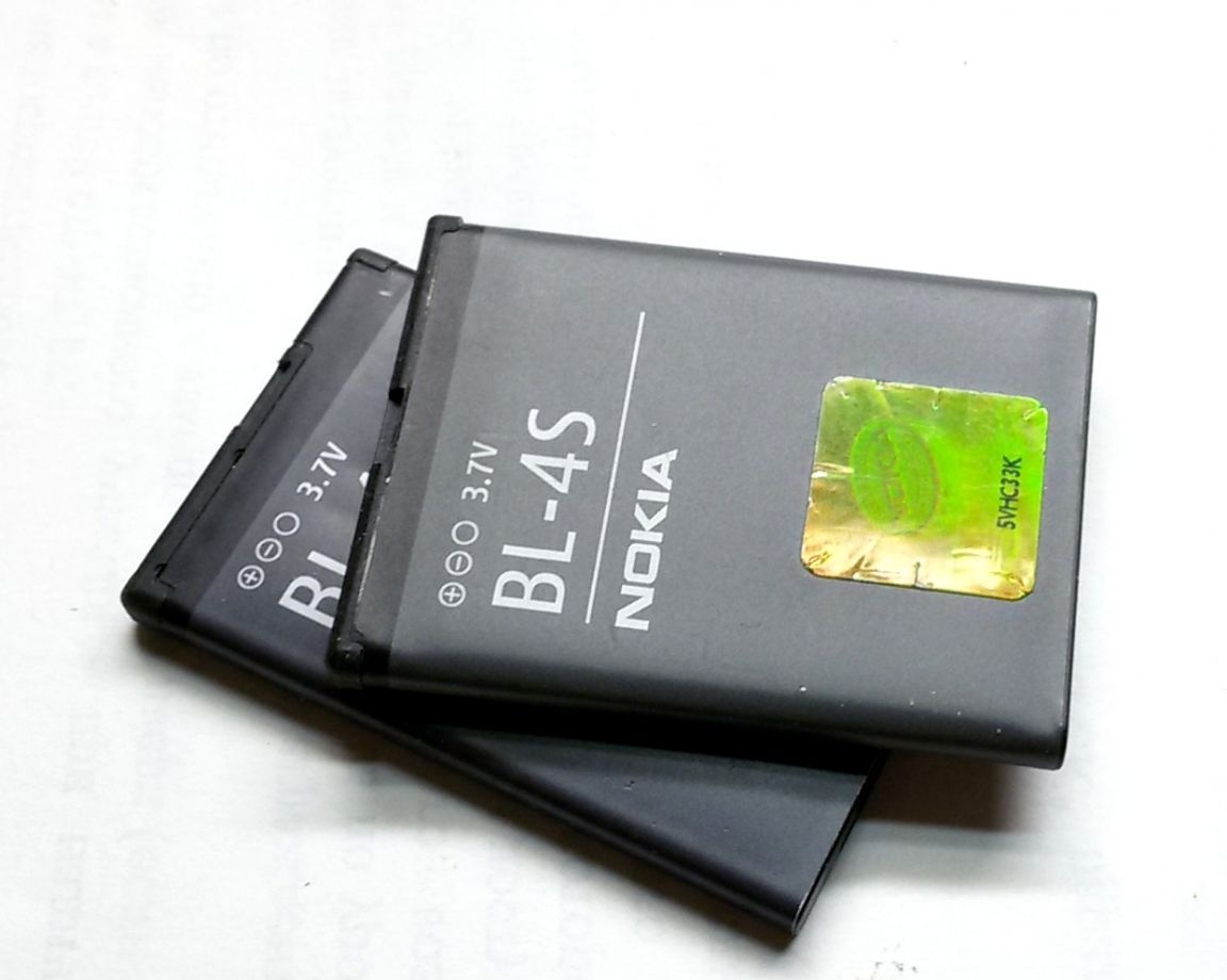
Today, many users have accumulated several working and unused lithium batteries that appear when replacing mobile phones with smartphones.
When using batteries in phones with their own charger, due to the use of specialized microcircuits for charge control, there are practically no problems with charging. But when using lithium batteries in various homemade the question arises, how and how to charge such batteries. Some people believe that lithium batteries already contain built-in charge controllers, but in fact, they have built-in protection schemes, such batteries are called protected. The protection schemes in them are mainly intended to protect against deep discharge and overvoltage when charging above 4.25V, i.e. This is an emergency protection, not a charge controller.
Some "friends" on the site here will also write that for a little money you can order a special board from China, with which you can charge lithium batteries. But this is only for fans of "shopping." It makes no sense to buy something that is easy to assemble in a few minutes from cheap and common parts. Do not forget that the ordered fee will have to wait about a month. Yes, and the purchased device does not bring such satisfaction as made do it yourself.
The proposed charger is able to repeat almost everyone. This scheme is very primitive, but completely copes with its task. All that is required for high-quality charging of Li-Ion batteries is to stabilize the output voltage of the charger and limit the charge current.
The charger is characterized by reliability, compactness and high stability of the output voltage, and, as is known, for lithium-ion batteries this is a very important characteristic when charging.
Charger diagram for li-ion battery
The charger circuit is made on an adjustable voltage regulator TL431 and a medium power bipolar NPN transistor. The circuit allows you to limit the charging current of the battery and stabilizes the output voltage.
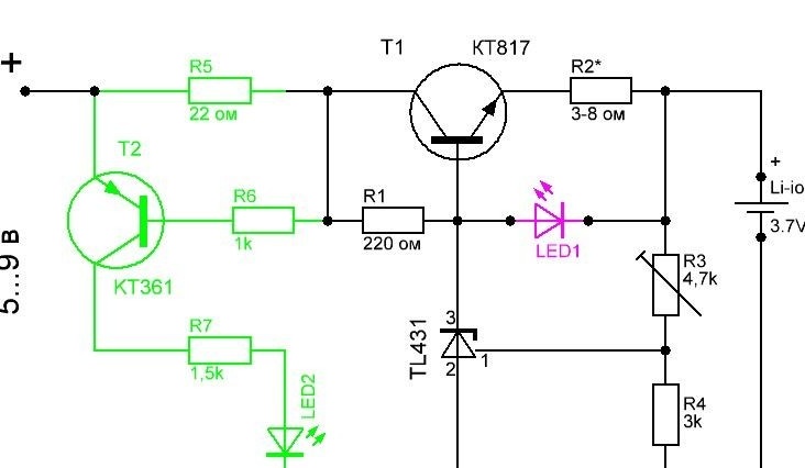
The role of the regulatory element is the transistor T1. Resistor R2 limits the charge current, the value of which depends only on the parameters of the battery. A 1 watt resistor is recommended. Other resistors may have a power of 125 or 250 mW.
The choice of transistor is determined by the required charging current set to charge the battery. For the case under consideration, charging batteries from mobile phones, one can use domestic or imported NPN transistors of medium power (for example, KT815, KT817, KT819). With a high input voltage or when using a low power transistor, it is necessary to install the transistor on a radiator.
LED1 (highlighted in red in the diagram) is used to visually signal the battery charge. When you turn on a discharged battery, the indicator glows brightly and dims as it charges. The indicator light is proportional to the battery charge current. But it should be noted that with the LED completely dying out, the battery will still be charged with a current of less than 50mA, which requires periodic monitoring of the device to prevent overcharging.
To improve the accuracy of monitoring the end of charge, an additional option for indicating the battery charge (highlighted in green) on the LED2, low-power PNP transistor KT361 and current sensor R5 has been added to the charger circuit. The device can use any variant of the indicator, depending on the required accuracy of the battery charge control.
The presented circuit is designed to charge only one Li-ion battery. But this charger can also be used to charge other types of batteries. It is only necessary to set the required output voltage and charging current.
Charger manufacture
1. We purchase or select from available components for assembly in accordance with the scheme.
2. Assembly of the circuit.
To check the operability of the circuit and its settings, we assemble the charger on the circuit board.
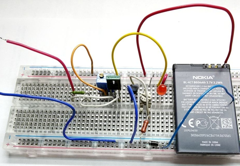
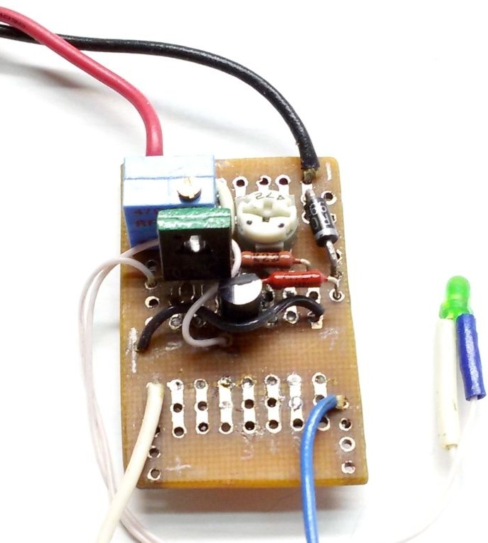
The diode in the battery power circuit (negative bus - blue wire) is designed to prevent the discharge of a lithium-ion battery in the absence of voltage at the input of the charger.
3. Setting the output voltage of the circuit.
We connect the circuit to a power source with a voltage of 5 ... 9 volts. With the trimming resistance R3, we set the output voltage of the charger in the range of 4.18 - 4.20 volts (if necessary, measure its resistance at the end of the setting and put the resistor with the desired resistance).
4. Setting the charging current of the circuit.
Having connected the discharged battery to the circuit (as the LED turns on), we set the charging current value (100 ... 300 mA) using the tester R2. With an R2 resistance of less than 3 ohms, the LED may not light.
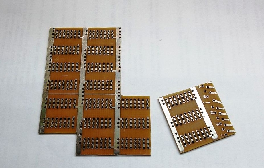
5. We prepare a board for mounting and soldering parts.
We cut out the required size from the universal board, carefully process the edges of the board with a file, clean and tidy the contact tracks.
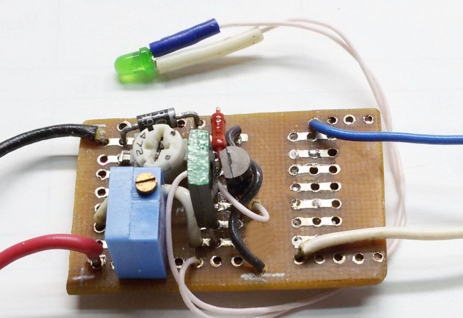
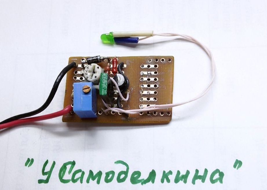
6. Installation of a debugged circuit on a working board
We transfer the parts from the circuit board to the working one, solder the parts, perform the missing wiring of the connections with a thin mounting wire. At the end of the assembly, we thoroughly check the installation.
The charger can be assembled in any convenient way, including wall mounting. When installed without errors and serviceable parts, it starts working immediately after switching on.
When connected to a charger, a discharged battery begins to consume maximum current (limited by R2). When the battery voltage approaches the set one, the charge current will fall and when the voltage on the battery reaches 4.2 volts, the charging current will be practically zero.
However, it is not recommended to leave the battery connected to the charger for a long time, because he does not like recharging even with a small current and can explode or catch fire.
If the device does not work, then it is necessary to check the control terminal (1) of TL431 for voltage.Its value must be at least 2.5 V. This is the smallest allowable value of the reference voltage for this chip. The TL431 chip is quite common, especially in computer PSUs.