Hello. Today I want to tell you about my homemade pipe bender, which I made this winter.
The idea of assembling such a machine was with me for a long time. With its help, it is possible to roll profile pipes, giving them the shape of an arc. Such an operation is very popular - you can collect, for example, a greenhouse, a canopy, a canopy over the entrance. You can give an interesting shape to the top edge of the gate, or a metal fence ...
... And this winter I found time and took up this homemade. When designing, I considered the following points:
Given that I am not going to use it professionally, I decided to make a relatively lightweight construction that is also easy to carry, and which will not take up much space during storage. (After all, I will bend pipes either near the house or in the country. I will not use it every year. And I certainly will not have to bend pipes of a large cross section). Therefore, I decided not to do a powerful stationary design with a large resource ...
.. The network has many descriptions of such machines. The principle of operation is the same for them - the basis is three shafts, one of which is movable in a vertical plane. It is he who bends the pipe and it, rolling along these shafts, takes on the shape of an arc.
... Basically, they are all divided into two types:
1. With a "breaking" bed:
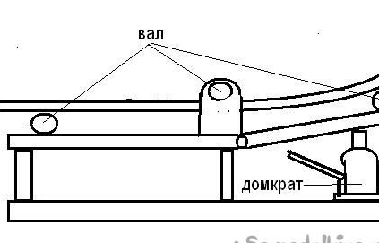
2. With a movable central carriage.
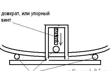
... In turn, pipe benders with a movable central carriage are also divided into two types: With a leading central shaft and with two leading extreme shafts connected to each other by a drive chain.
If you make the central shaft leading, that is, you can easily change the distance between the extreme ones, which will give additional adjustment of work depending on the cross-section (and therefore rigidity) of various profile pipes.
At first, I doubted whether there would be slippage if only one shaft was leading, but having observed a pipe bender with one leading shaft in operation, I realized that this effort is quite enough on not very large sections. And I'm not going to bend pipes with a height greater than, for example, 60 mm ... Therefore, I settled on such a device.
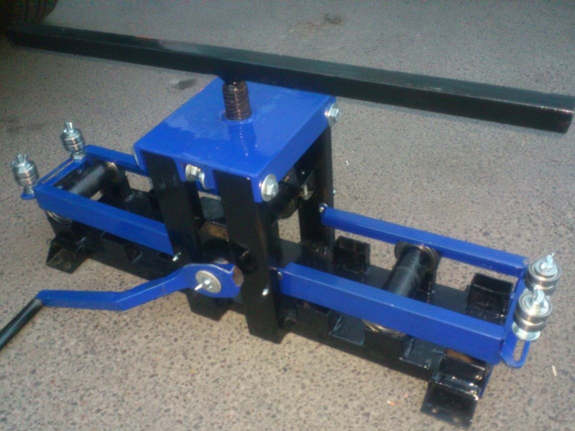
And after some time, I got a pipe bender, which you will see in this video:
[media = https: //youtu.be/cPpXJBXcmIo]
So, more ... I needed:
1. Old defective hydraulic jack
2.Profile pipes of various sections.
3. A circle with a diameter of 40 mm, a length of 500 mm.
4. Bearings 6206 4pcs
5. Bearings 6202 8 pcs.
6. Channel number 65
7. Thrust bearings 2 pcs.
8. Hardware (bolts, nuts, washers, cotter pins)
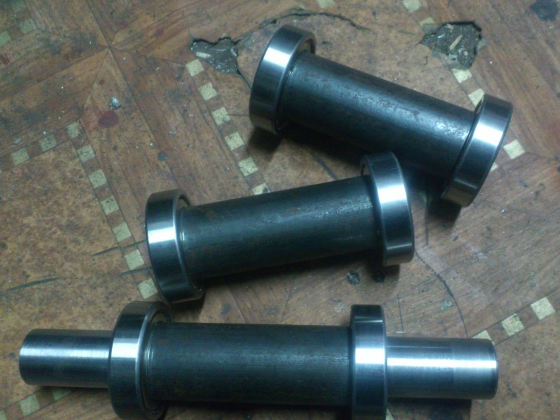
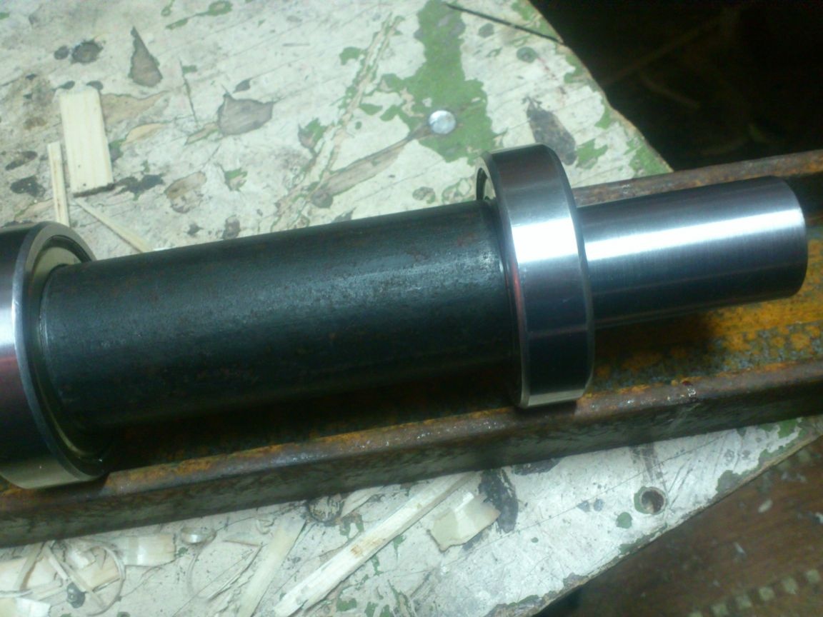
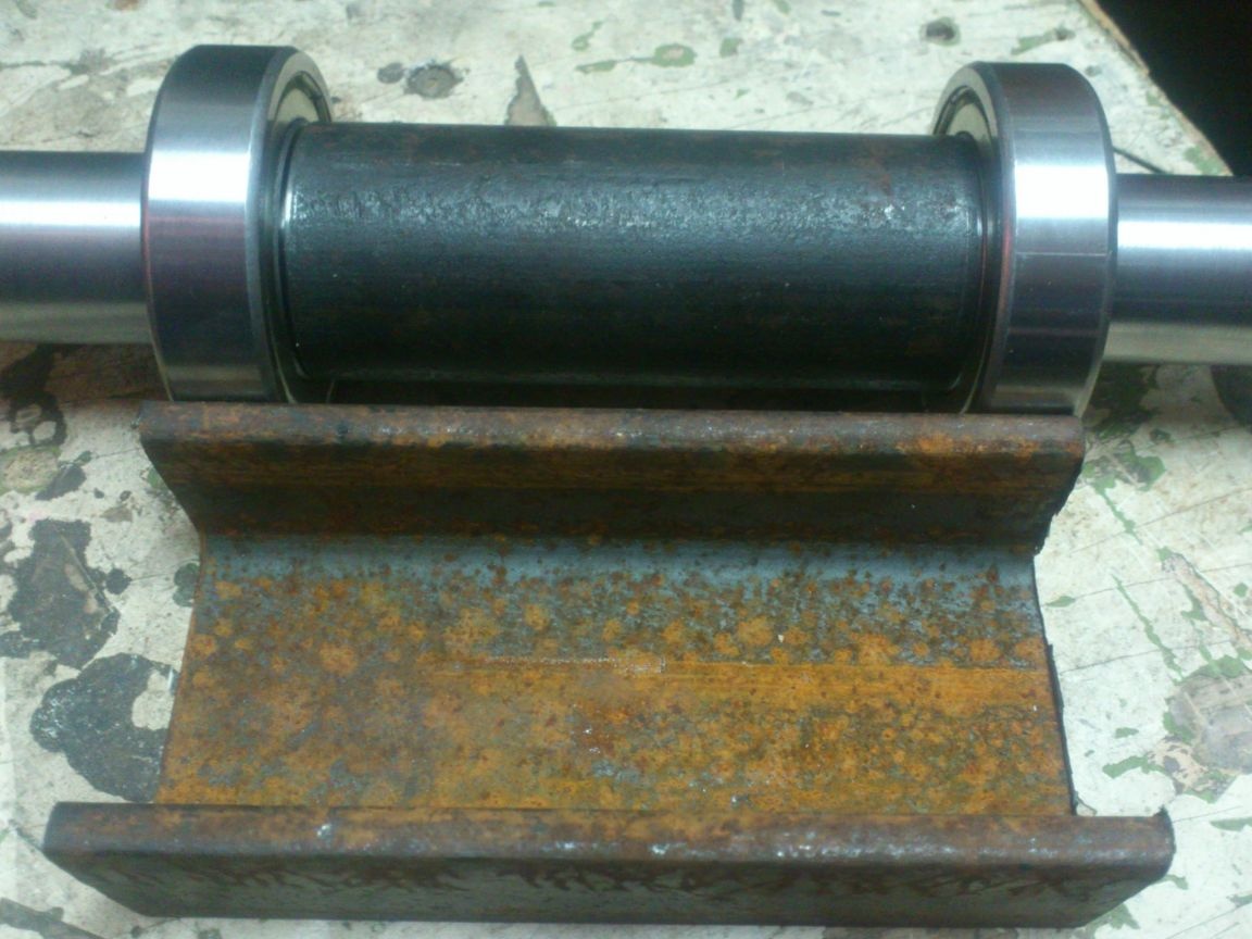
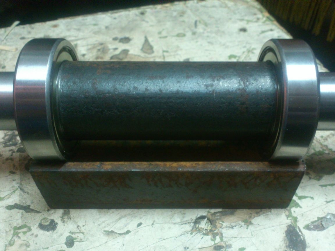
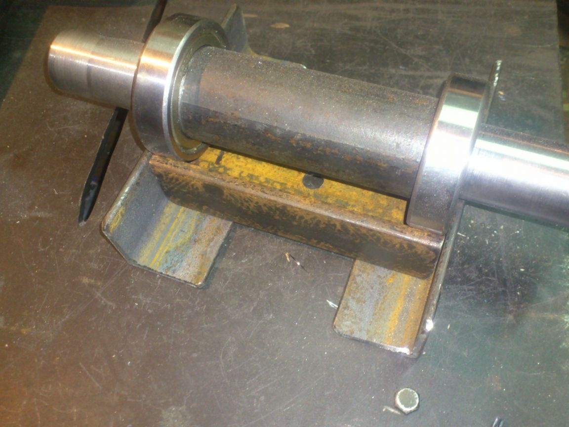
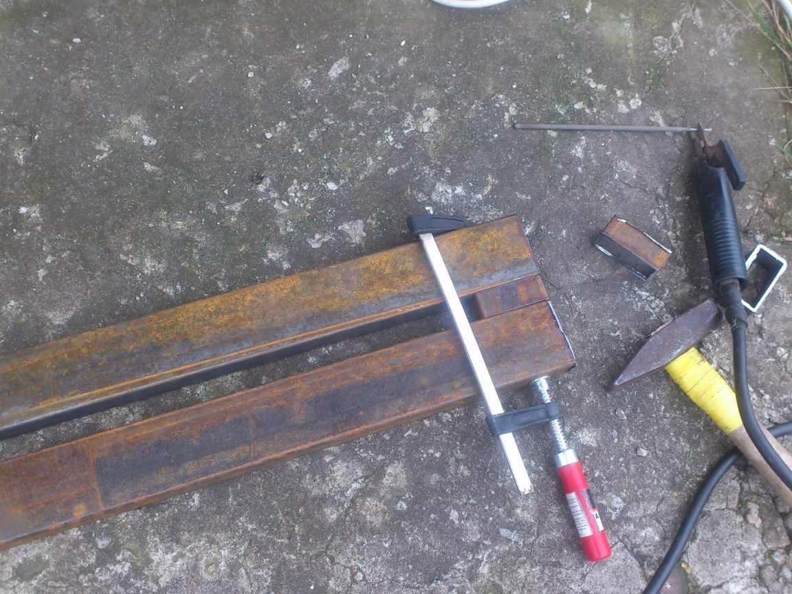
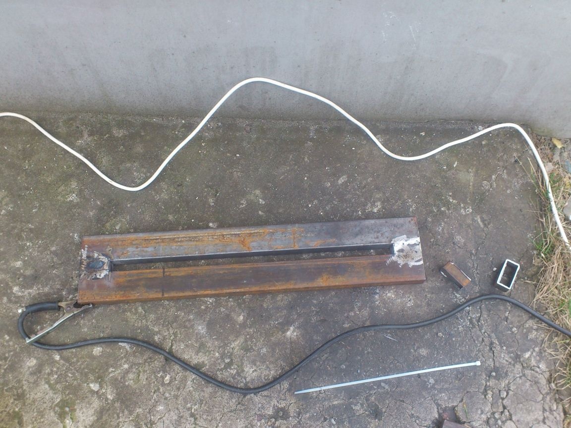
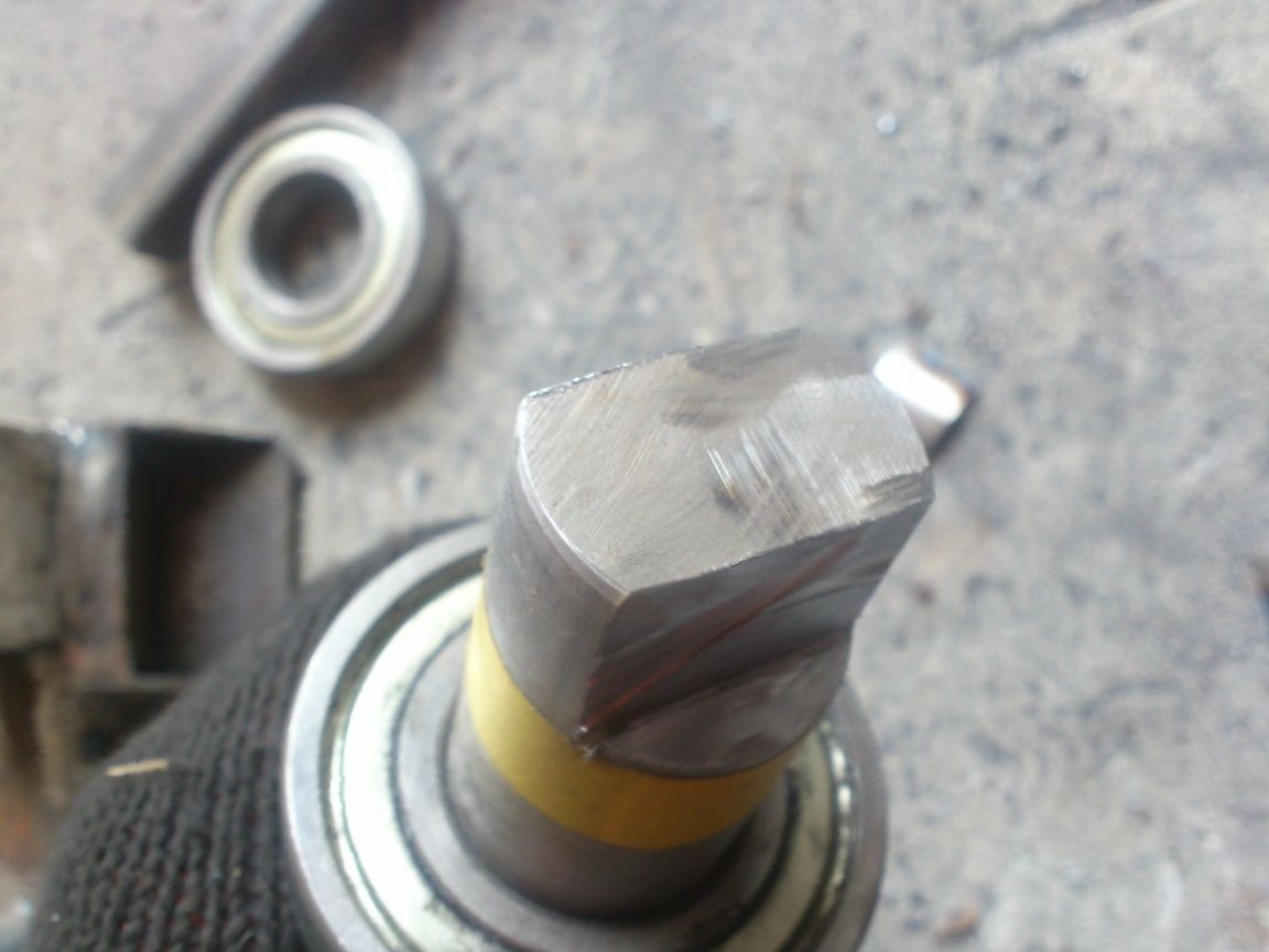
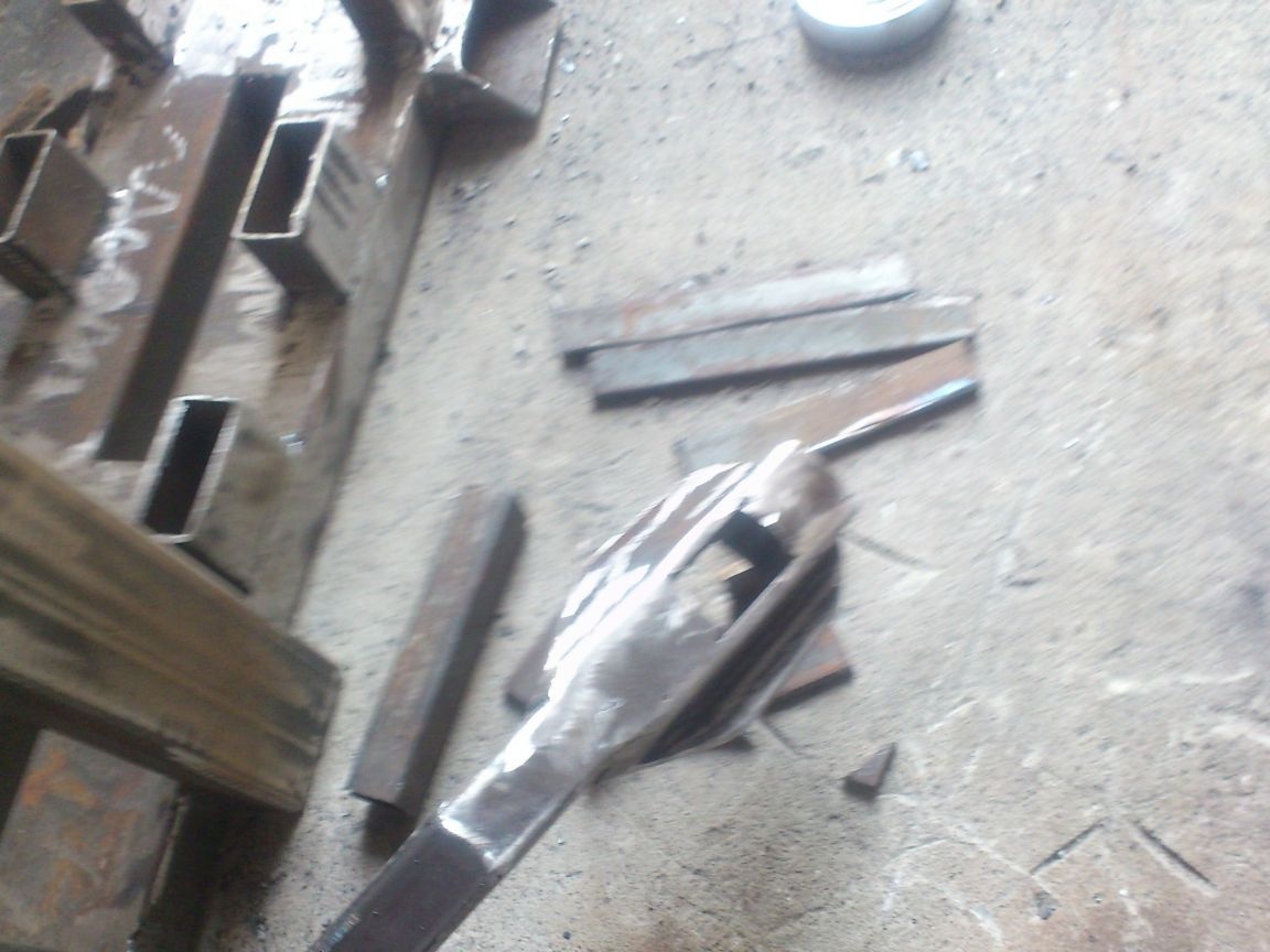
I began with the manufacture of the main working elements - shafts. I had a 40 mm round, half a meter long. You could take it thicker, but ... I had this one! ))). And so I sawed it into three parts. Two - 130 mm each, and one - all that remains))))). On a lathe, he machined shafts for bearings (up to 30 mm in diameter)
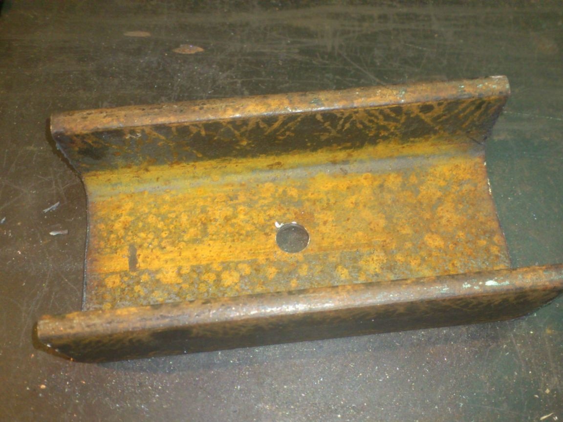
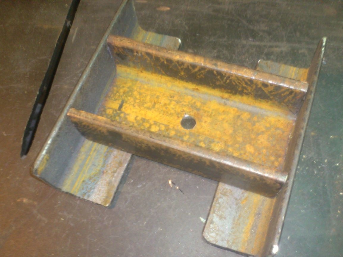
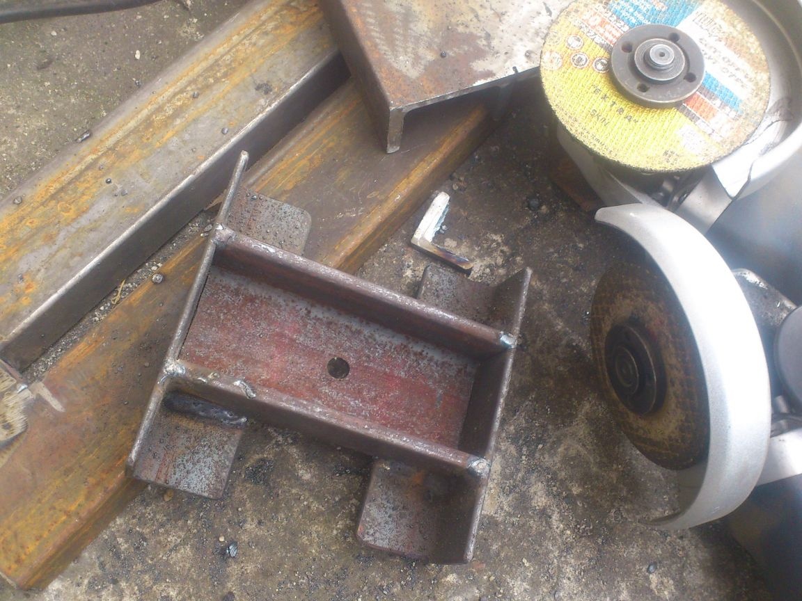
The shafts are ready. I started assembling the carriage. I decided to make it from the 65th channel - the 206th bearings fit well into it ...
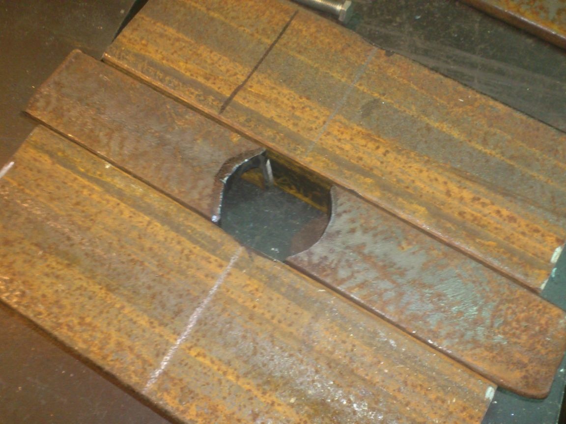
After I cut the channel of the required length, I drilled a hole in its center, and welded across the sides in the corner:
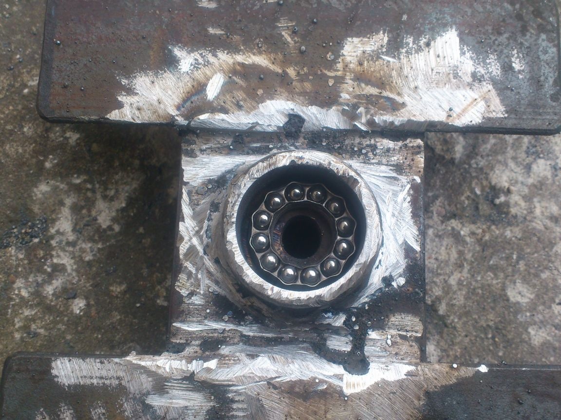
After that, I started to manufacture the central screw. I took it from an old hydraulic jack that I found in scrap metal. When I became convinced that he would never be a jack, I decided to use it.
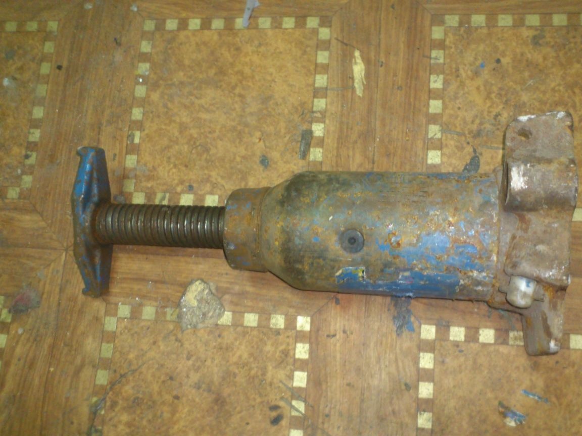
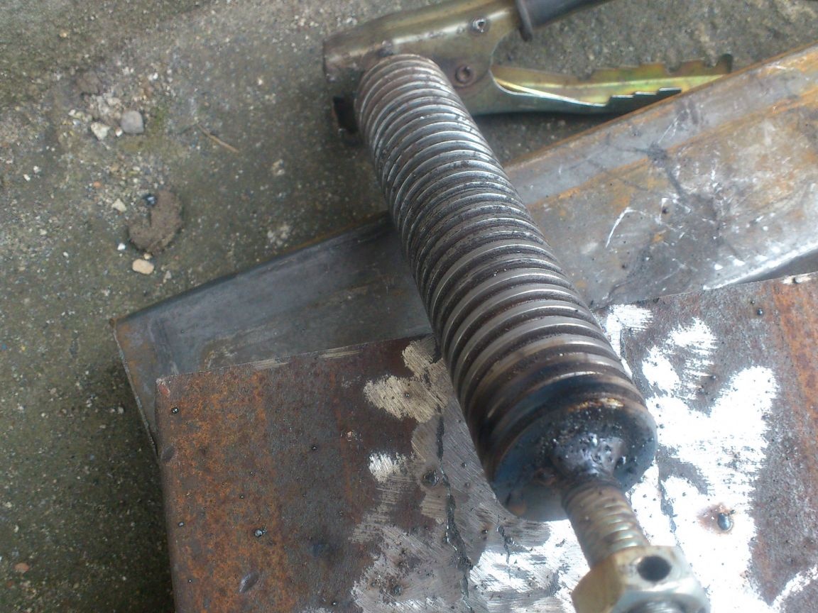
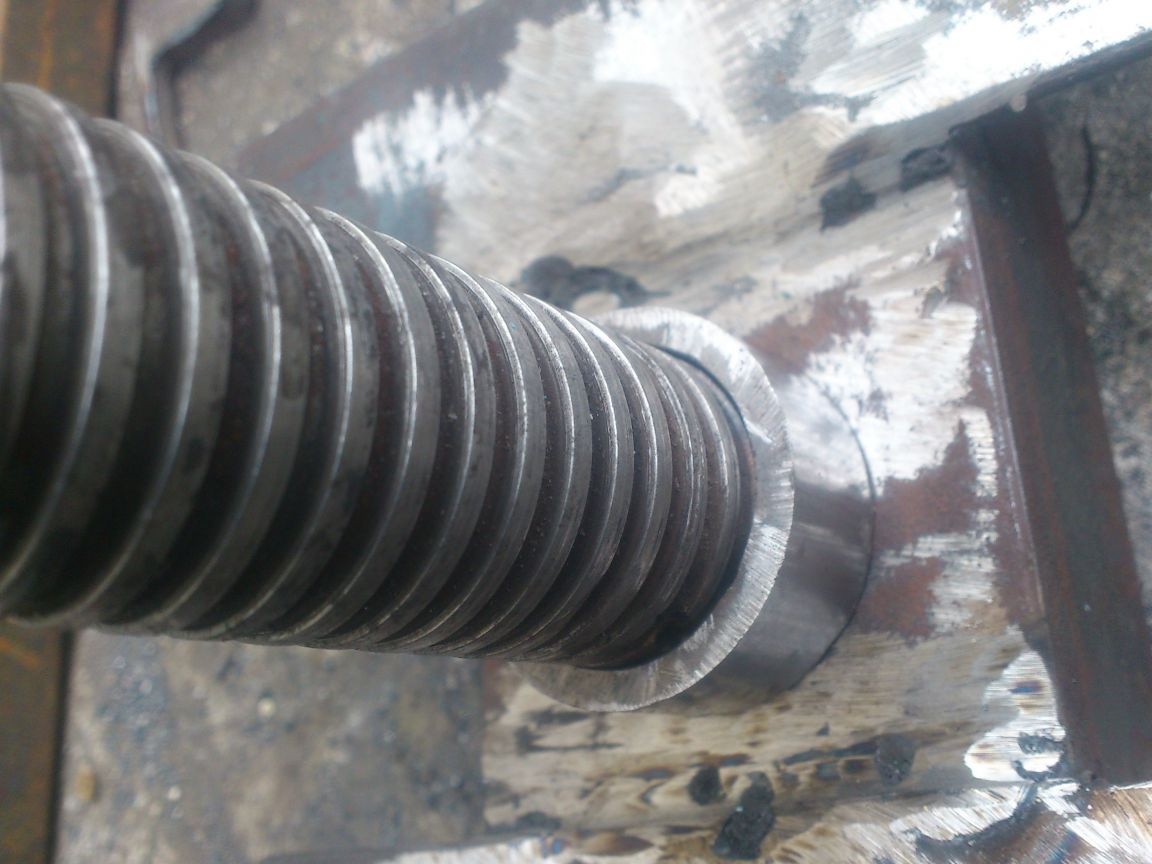
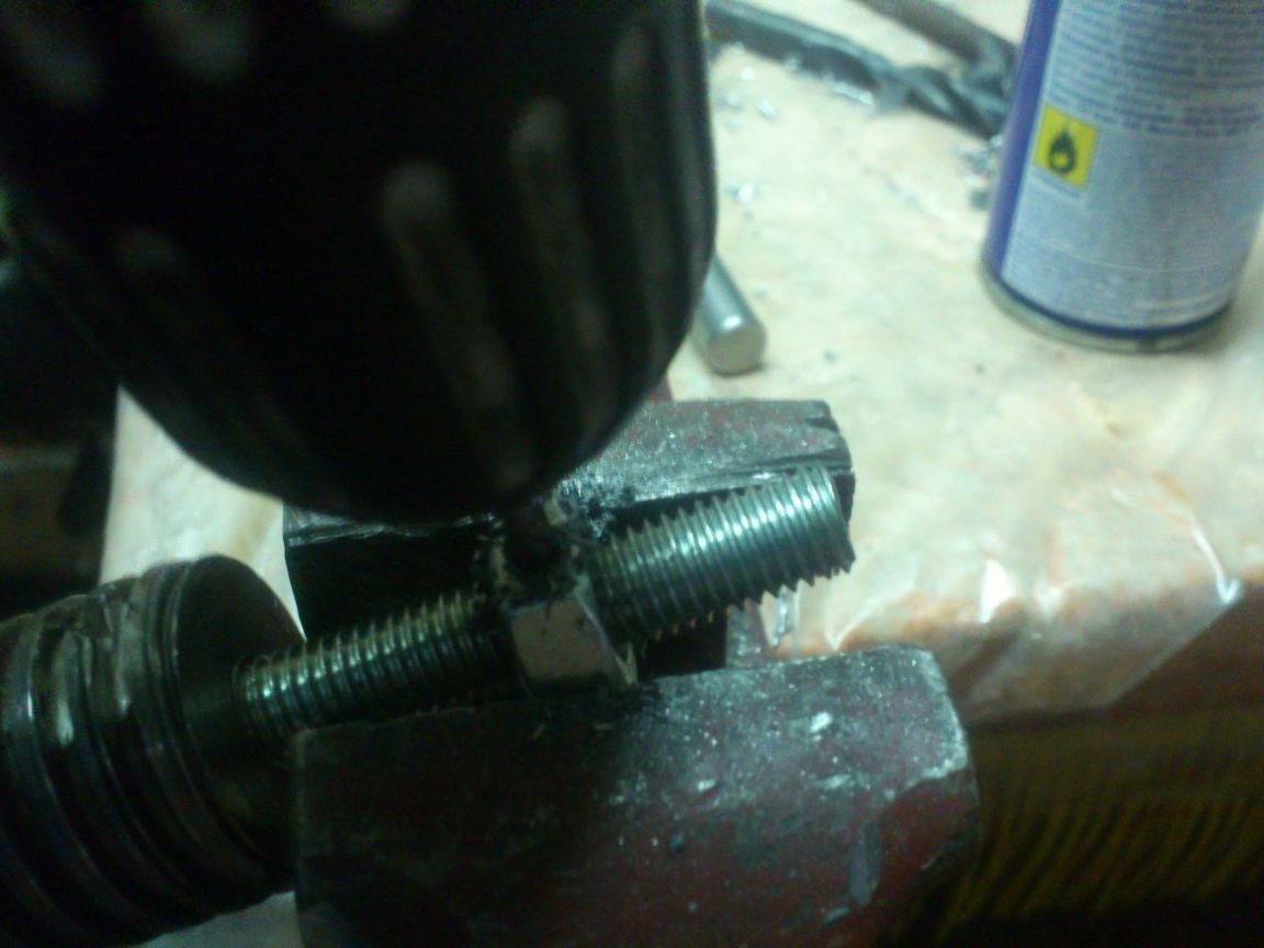
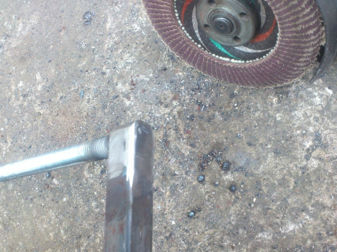
The screw itself was 30 mm in diameter. At its end, with an 8mm drill, I drilled a blind hole, hammered a pin there and grabbed it with welding:
The screw in the jack was screwed into the piston. I cut off the upper part (with thread) and another ring, 20 mm wide.
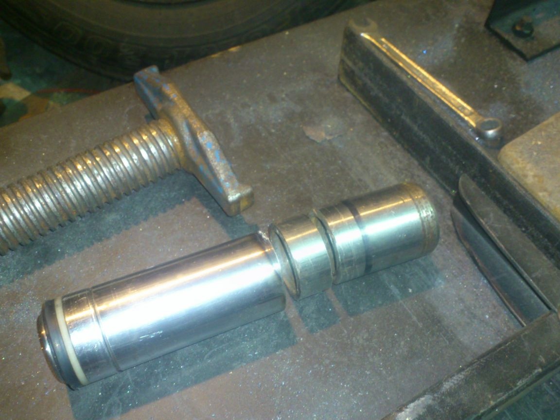
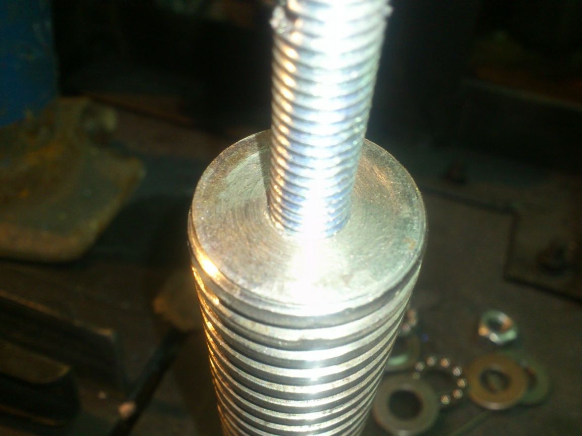
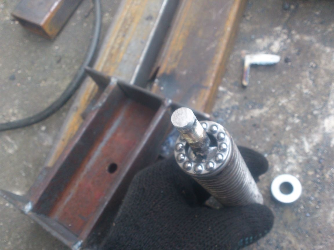
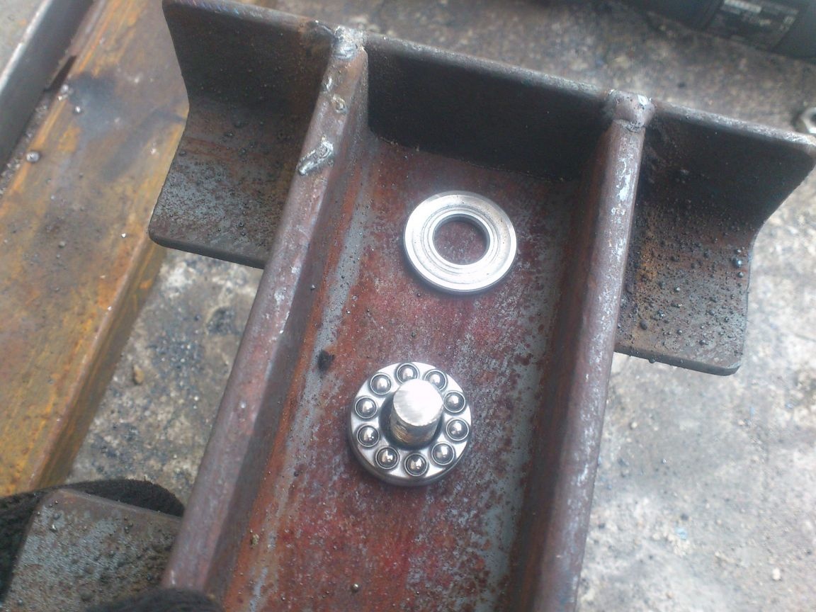
This will be the footprint for the bearing support. (I picked it up by the outer diameter)
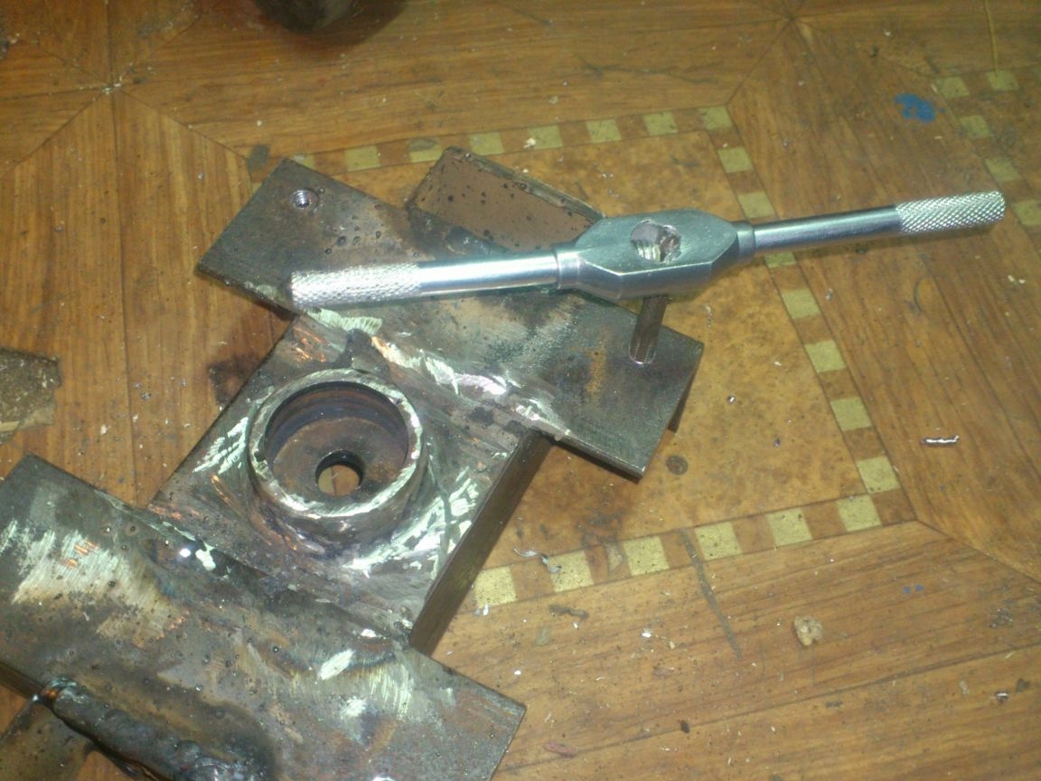
I screwed a nut onto the stud, and drilled a hole in the nut and in the stud:
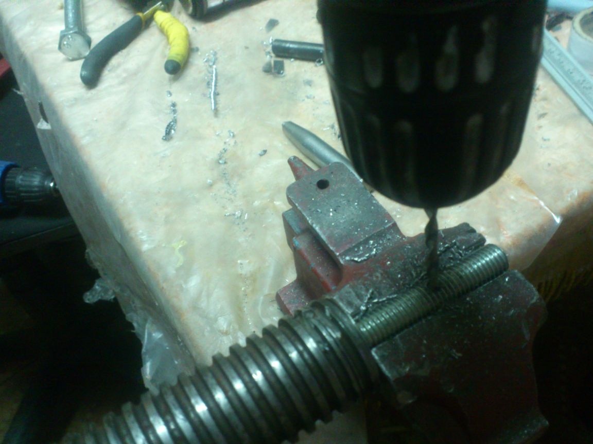
It was possible only in a hairpin, but it seemed to me more reliable. Now the nut can be splinted after assembly of the assembly. And the assembly, you guessed it, consists of a screw, a bearing, a carriage, a second bearing and a nut.
Now, when pressed, the screw will abut the carriage through the upper bearing, and when lifted, the carriage will hang on it through the lower one.
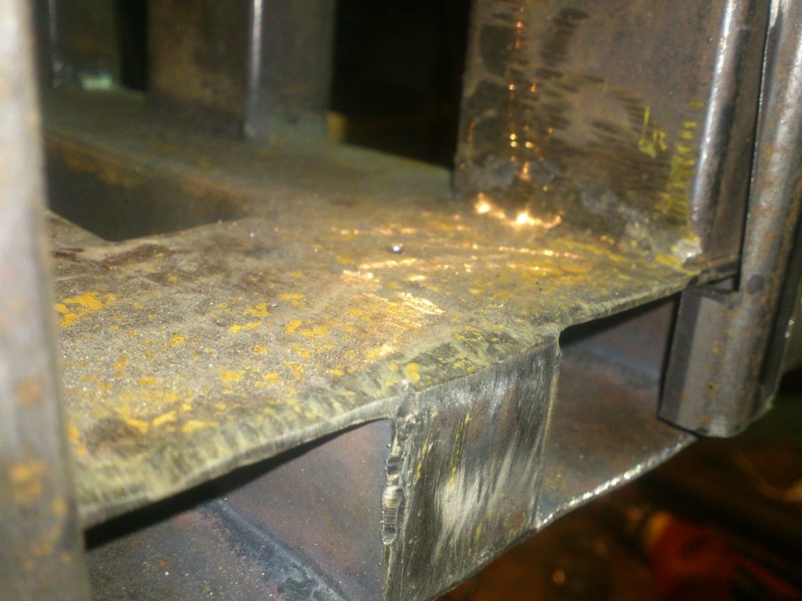
On the sides of the carriage I welded a 50 to 20 profile pipe to be cut - these will be the guides, and in the corners I drilled holes and cut the M6 thread. Bolts of fastening of collars of a leading shaft will be screwed into them.
I cut the bearing clamps themselves out of tin - there is no need for fortresses there, if only the shaft would not fall when lifting the carriage:
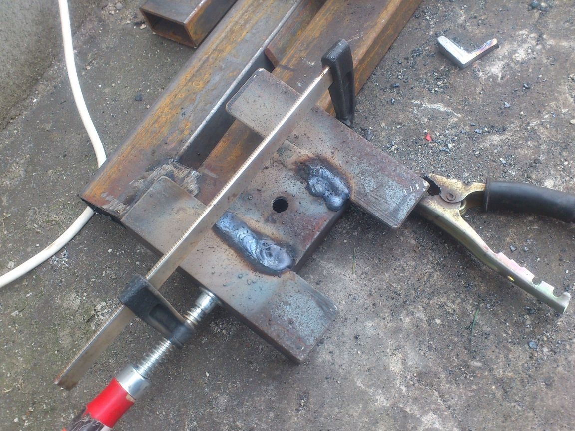
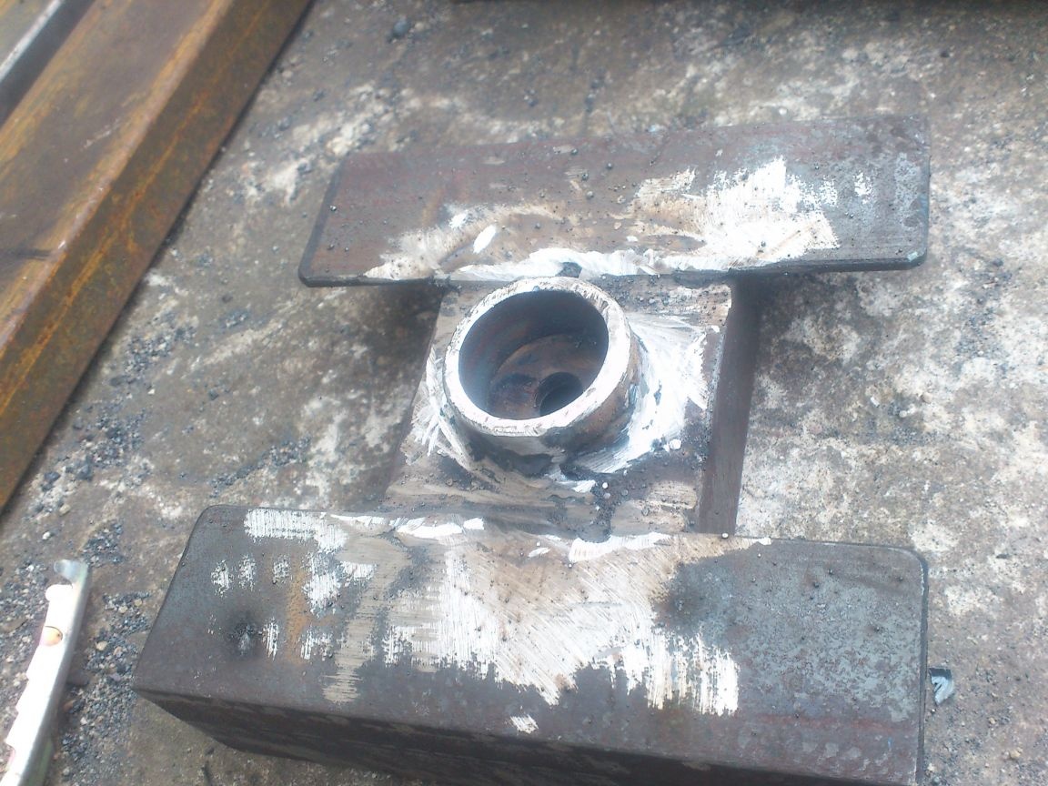
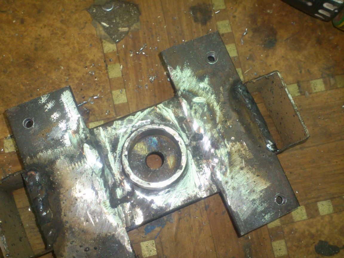
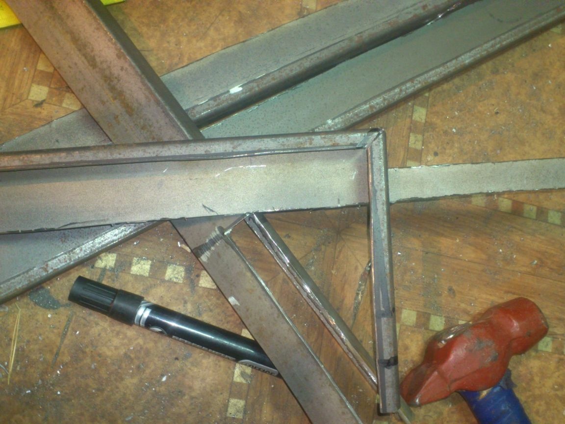
Next, I began to manufacture the top plate. It needs to be made very durable - it will account for the entire effort of the screw when it bends the pipe. Therefore, I made it from the same 65th channel. Since I decided to use a 50 by 25 profile pipe for vertical posts (the distance between the shelves of the 65th channel is just 50 mm. The posts will go into it and fasten with M10 bolts and nuts), then the width of the top plate should be 50 mm larger carriage width (2 times 25). I cut out two such pieces of the channel.
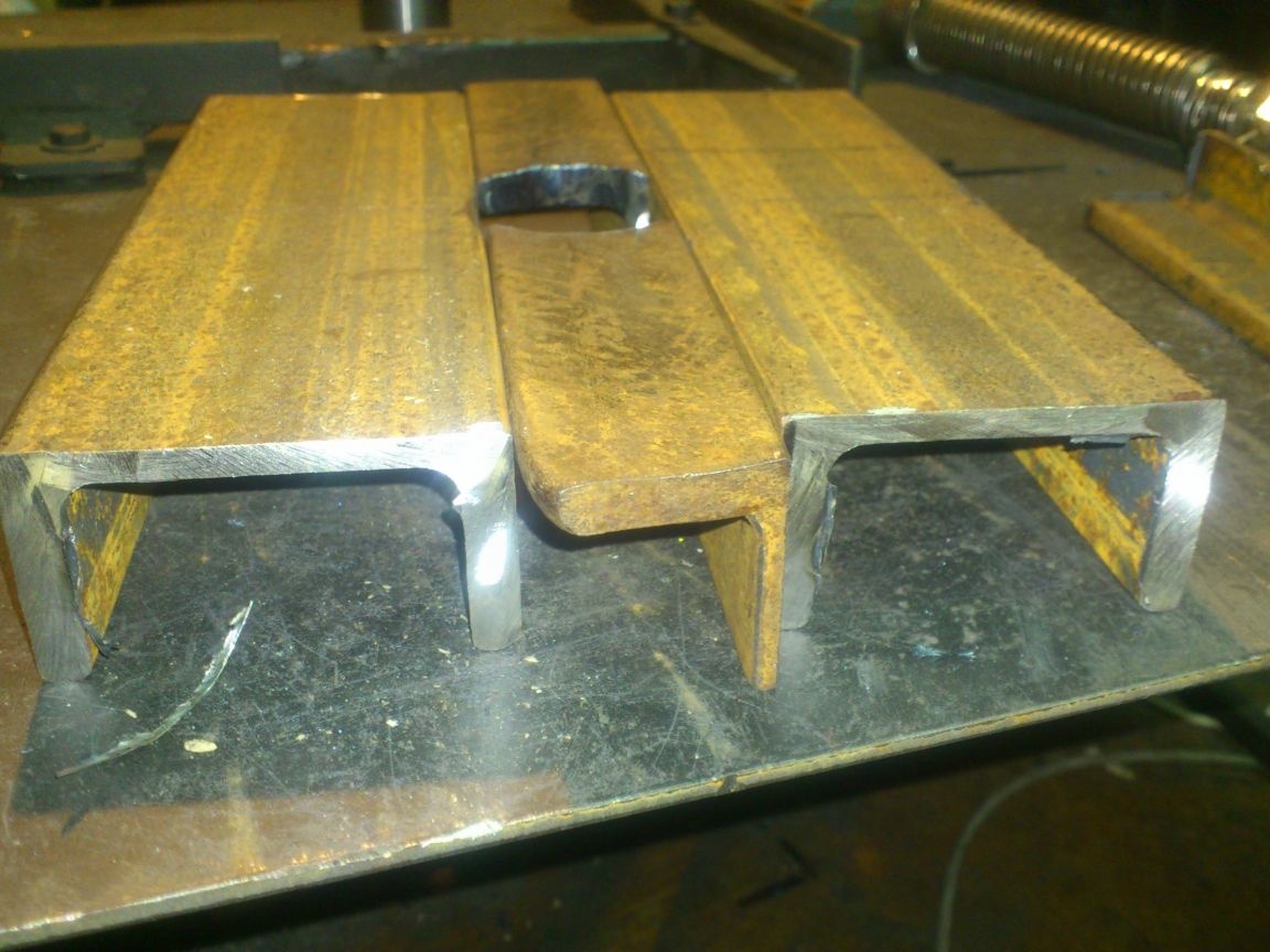
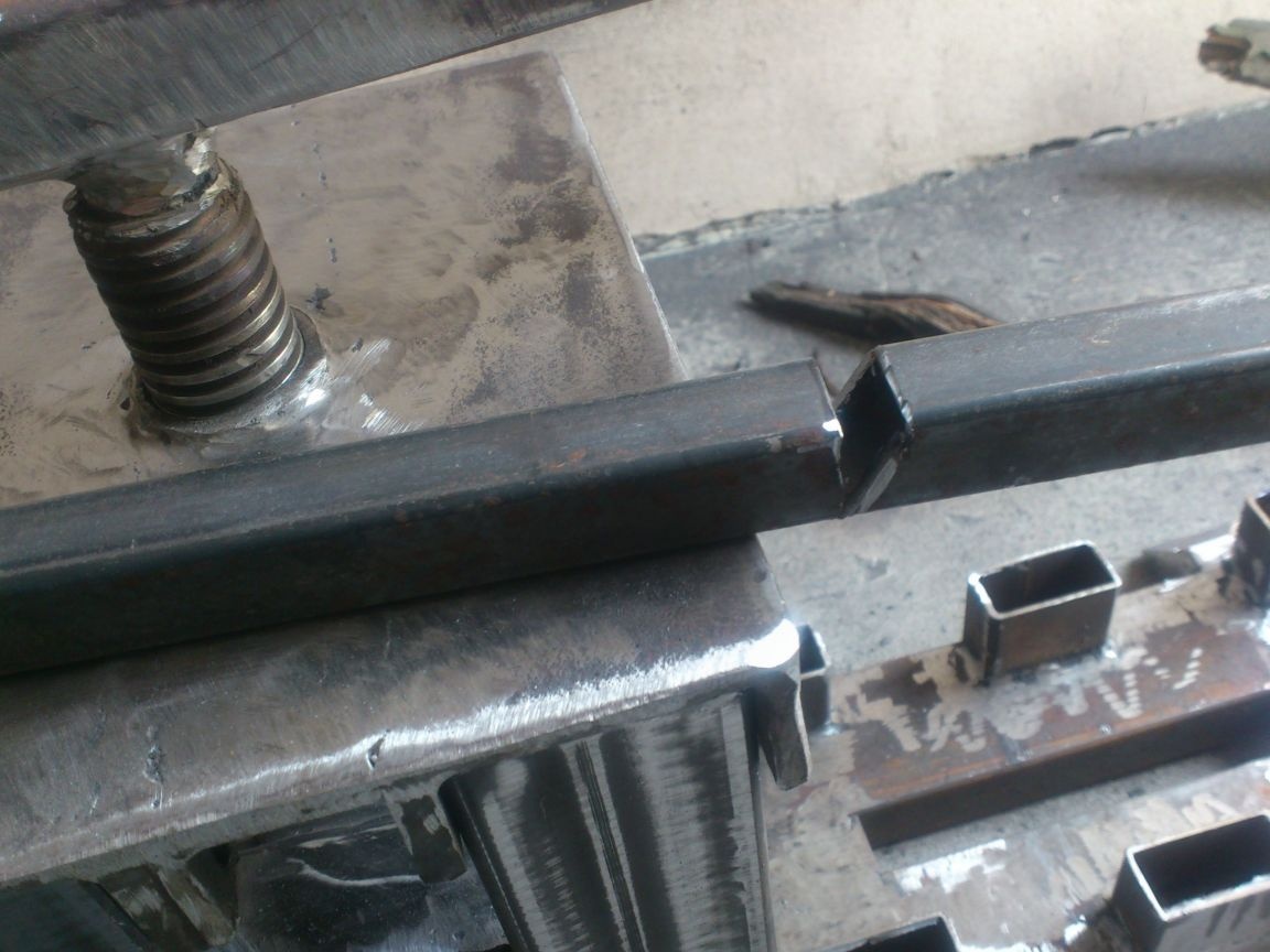
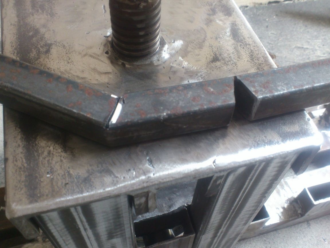
I inserted a threaded part cut off from the piston of the jack into the center:
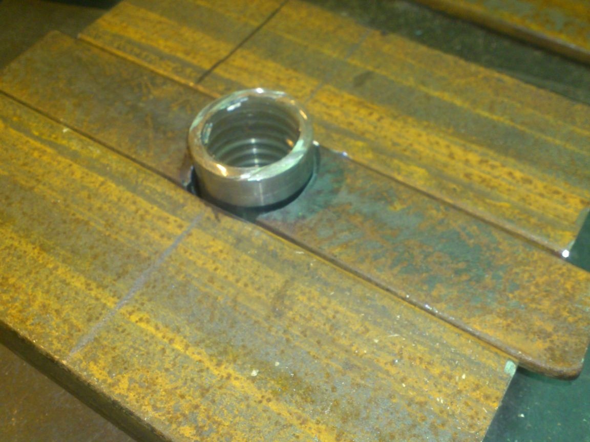
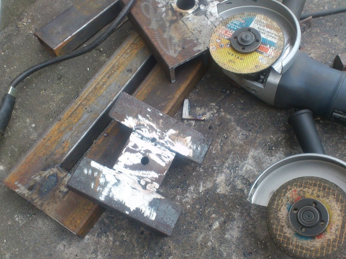
I cooked everything and cut off the excess:
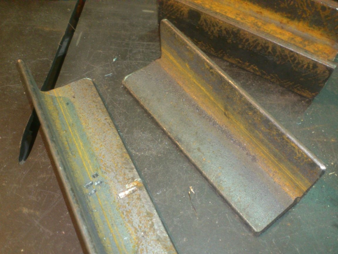
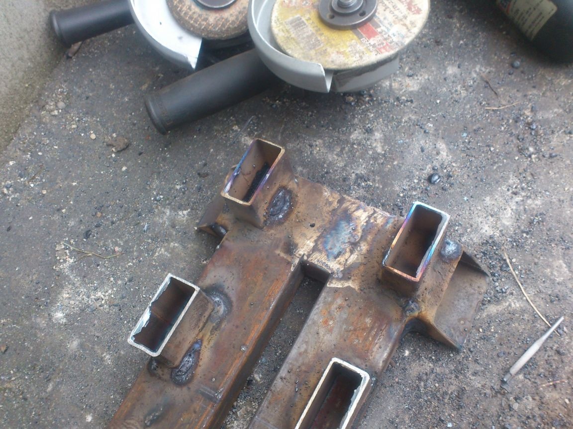
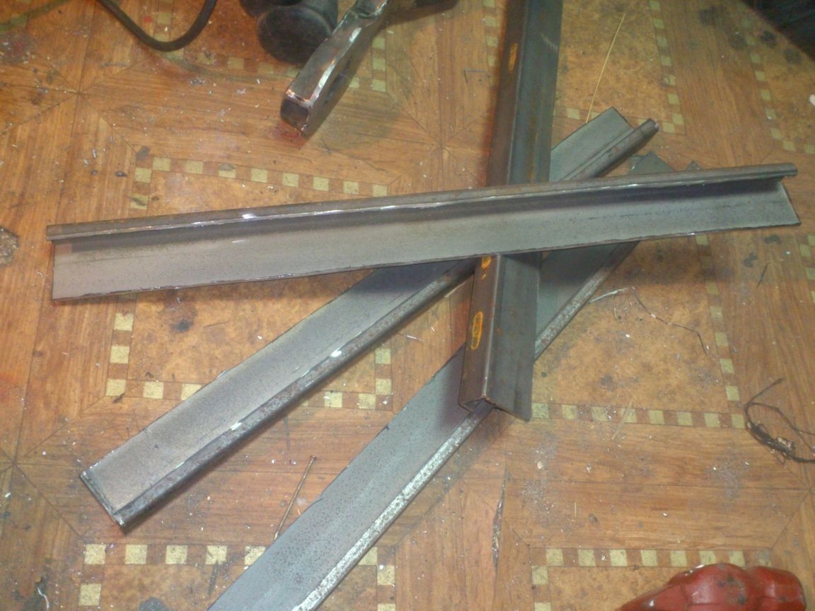
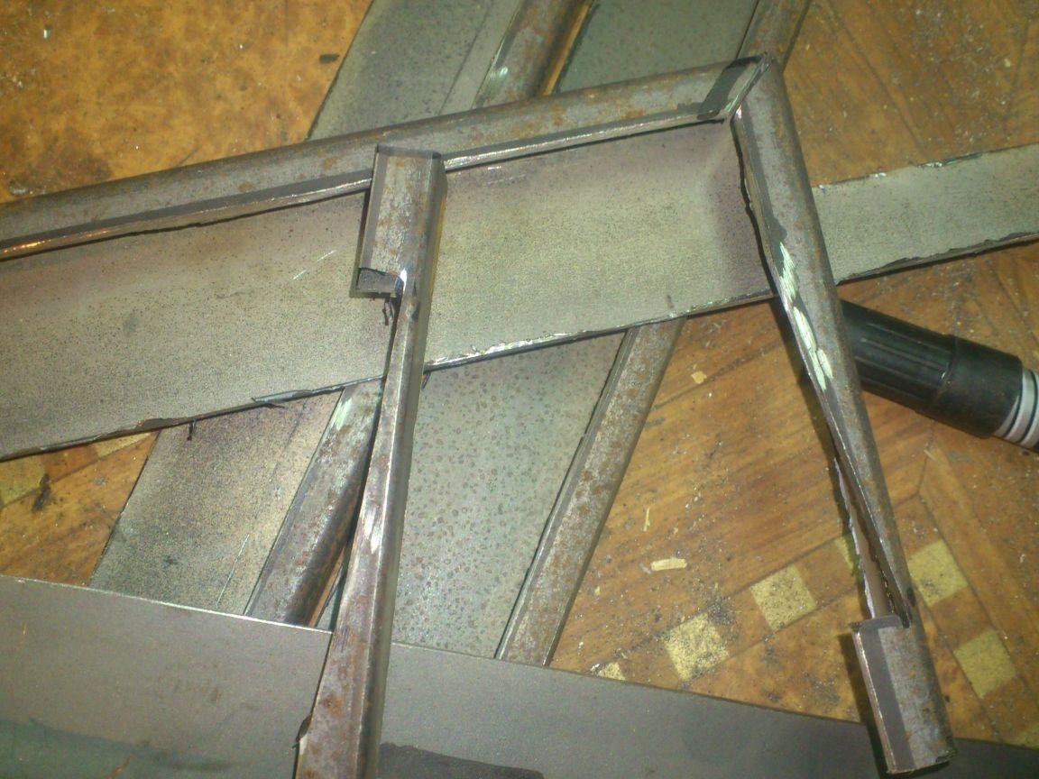
Next, I proceeded to make the bed. She also assembled from a profile pipe. The section took 60 to 30:
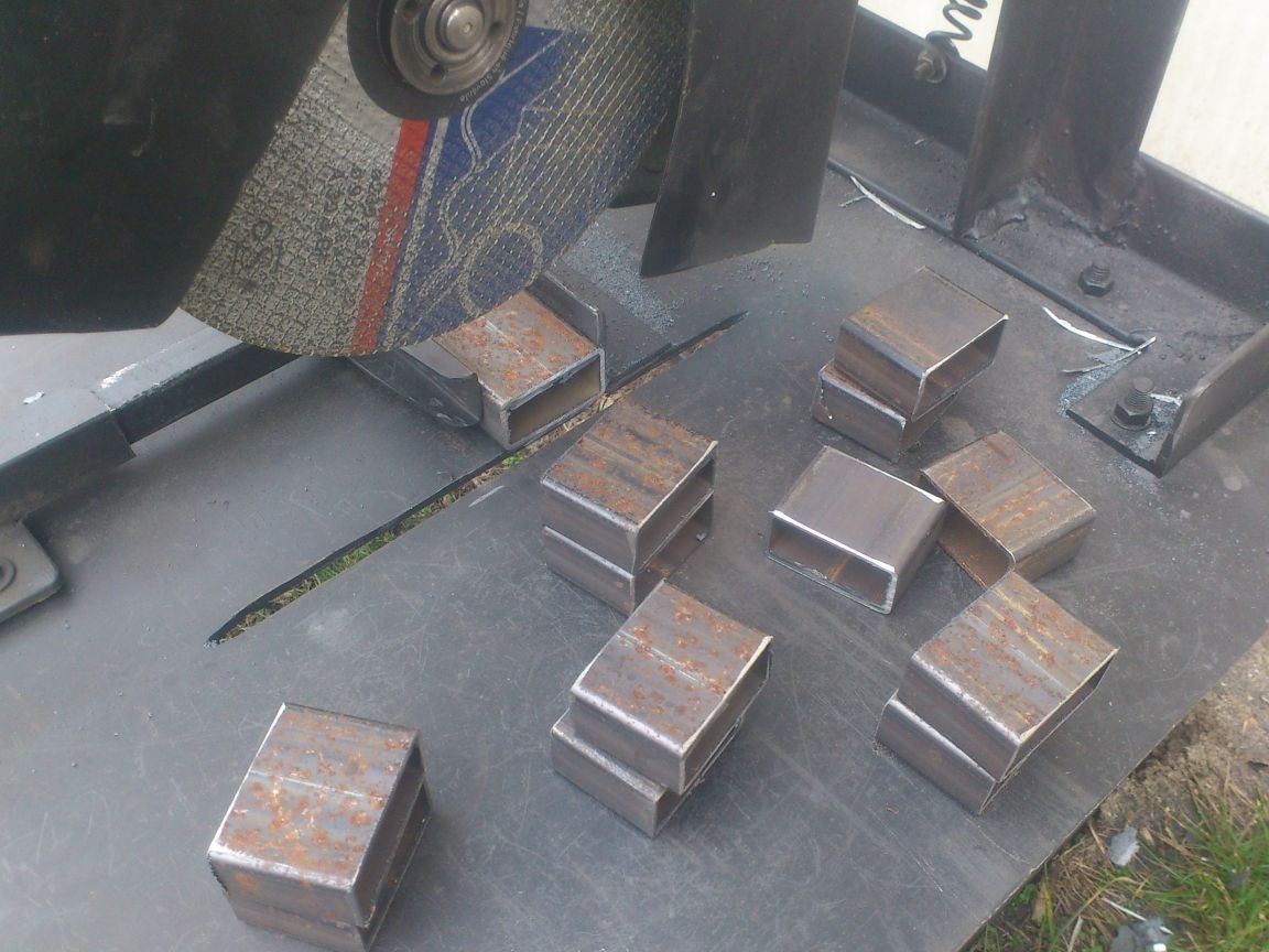
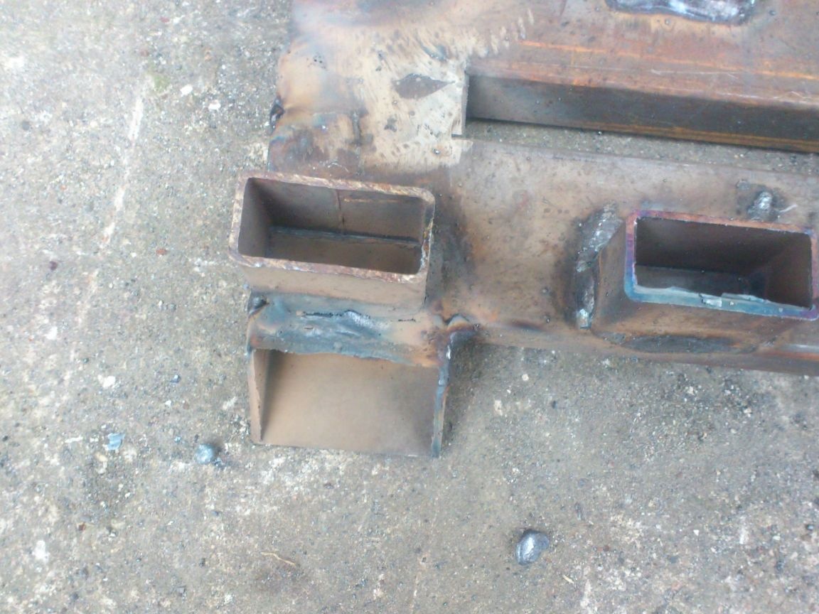
I decided to make three positions for each shaft. I also made landing gears for bearings from a profile pipe, so I cut off 12 identical pieces of 50 mm each. (Here, and not only here, my help a lot homemade cutting machine, which I told you about in a previous post):
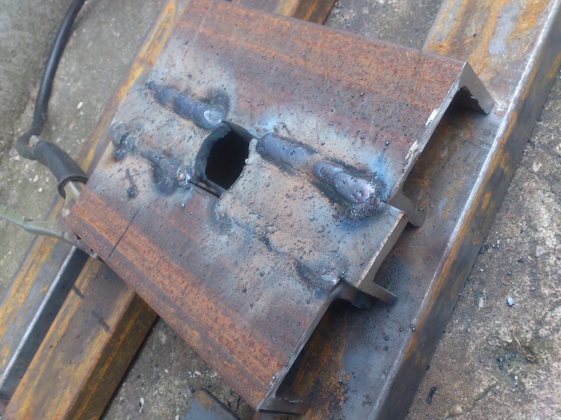
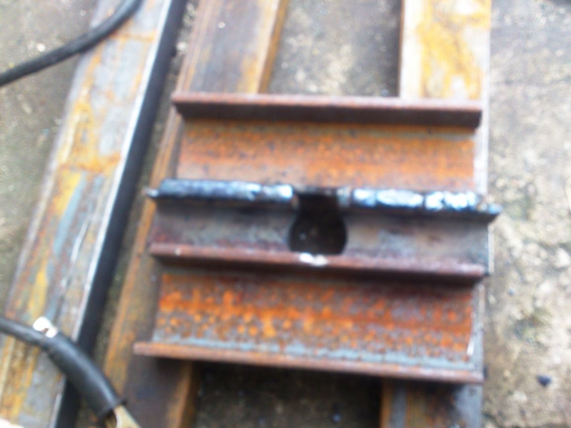
After that I welded vertical racks and landing bearings for bearings to the bed:
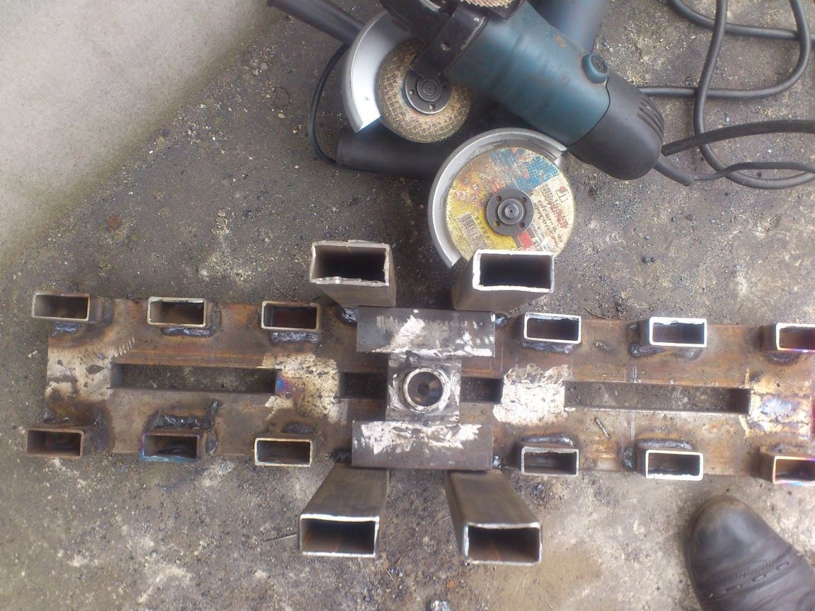
And also four "ears" around the edges. Later, holes will be drilled in them for fastening the pipe bender with screws to the workbench.
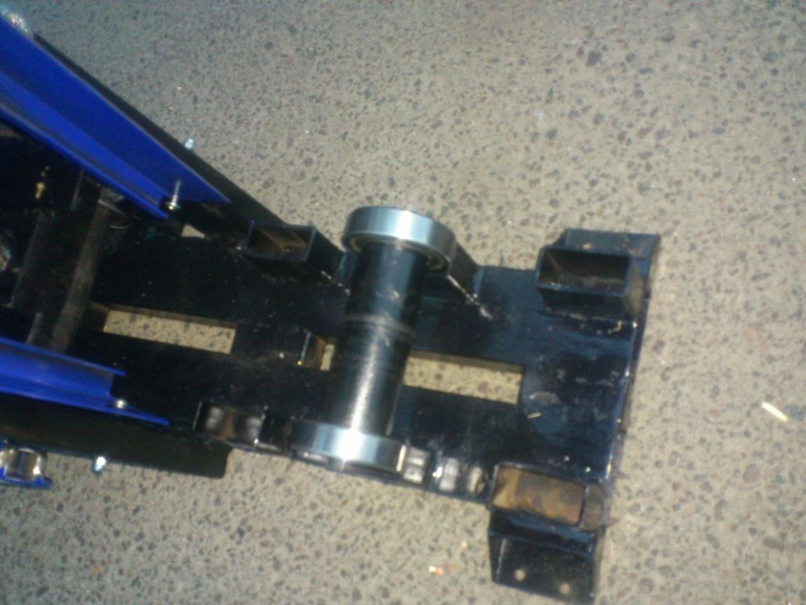
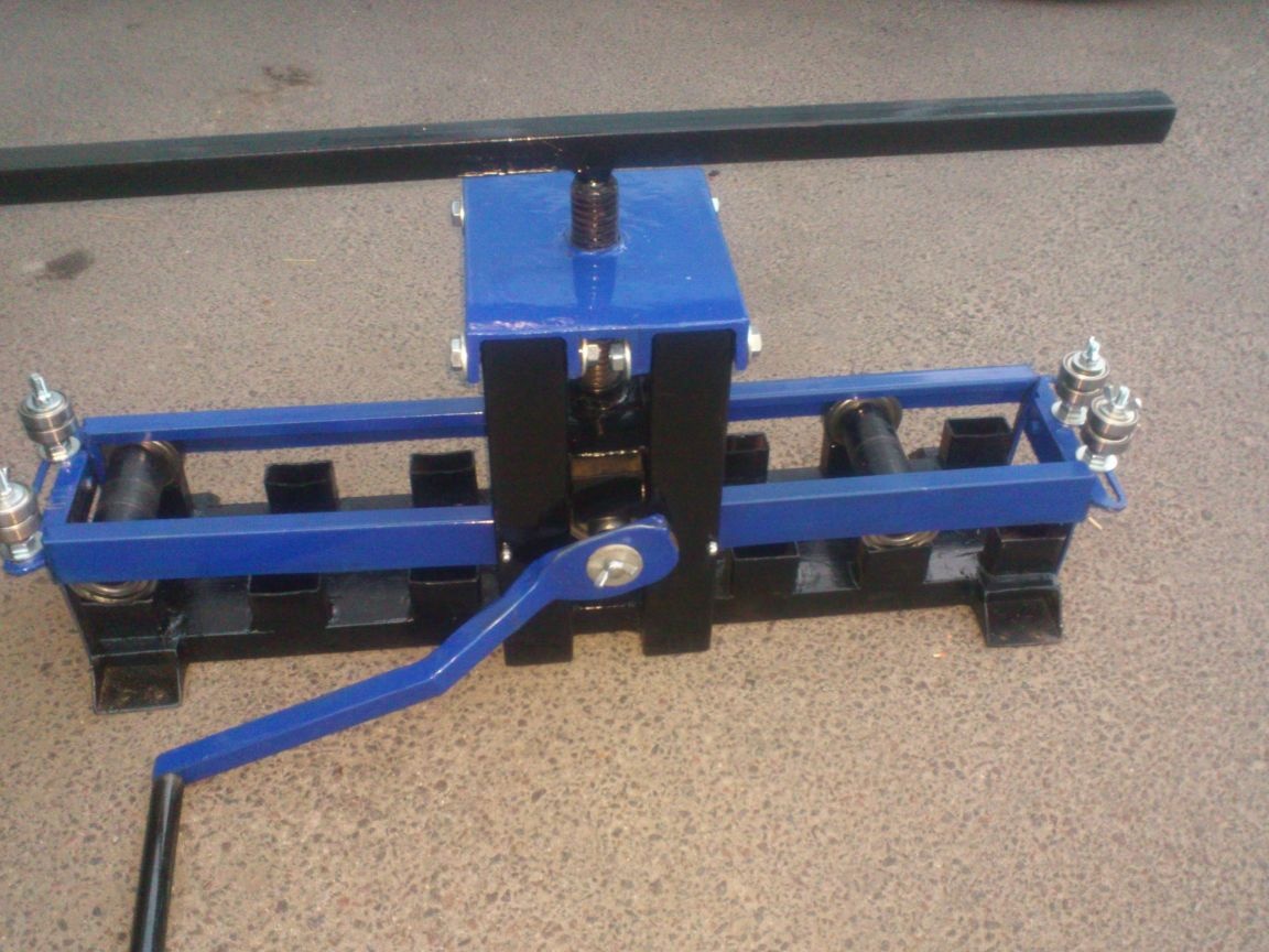
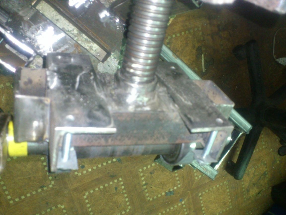
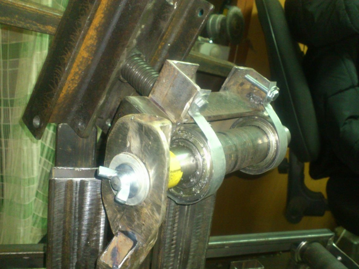
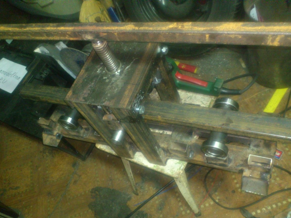
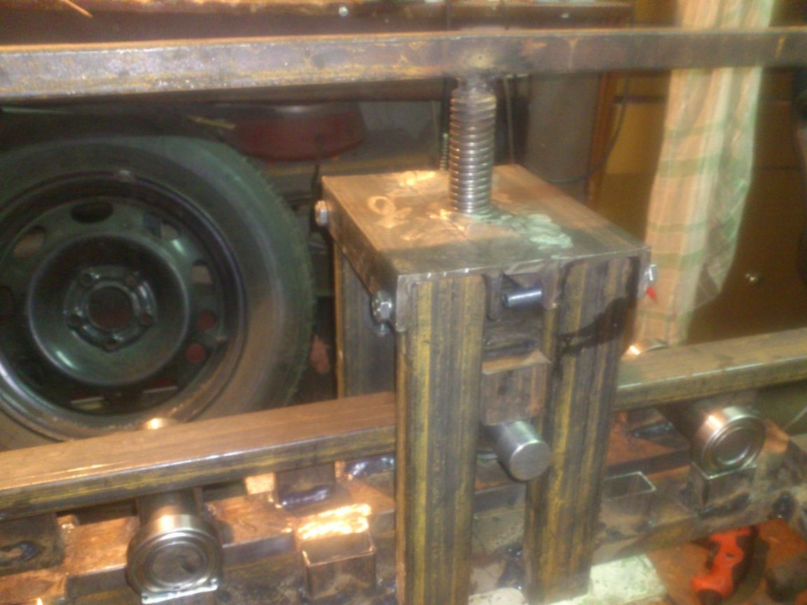
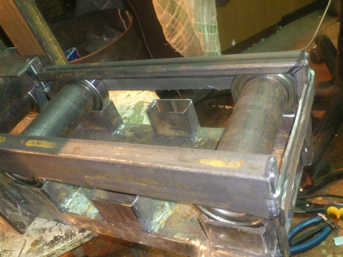
The main part is ready. You can proceed to the preliminary assembly:
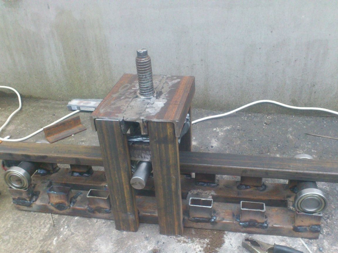
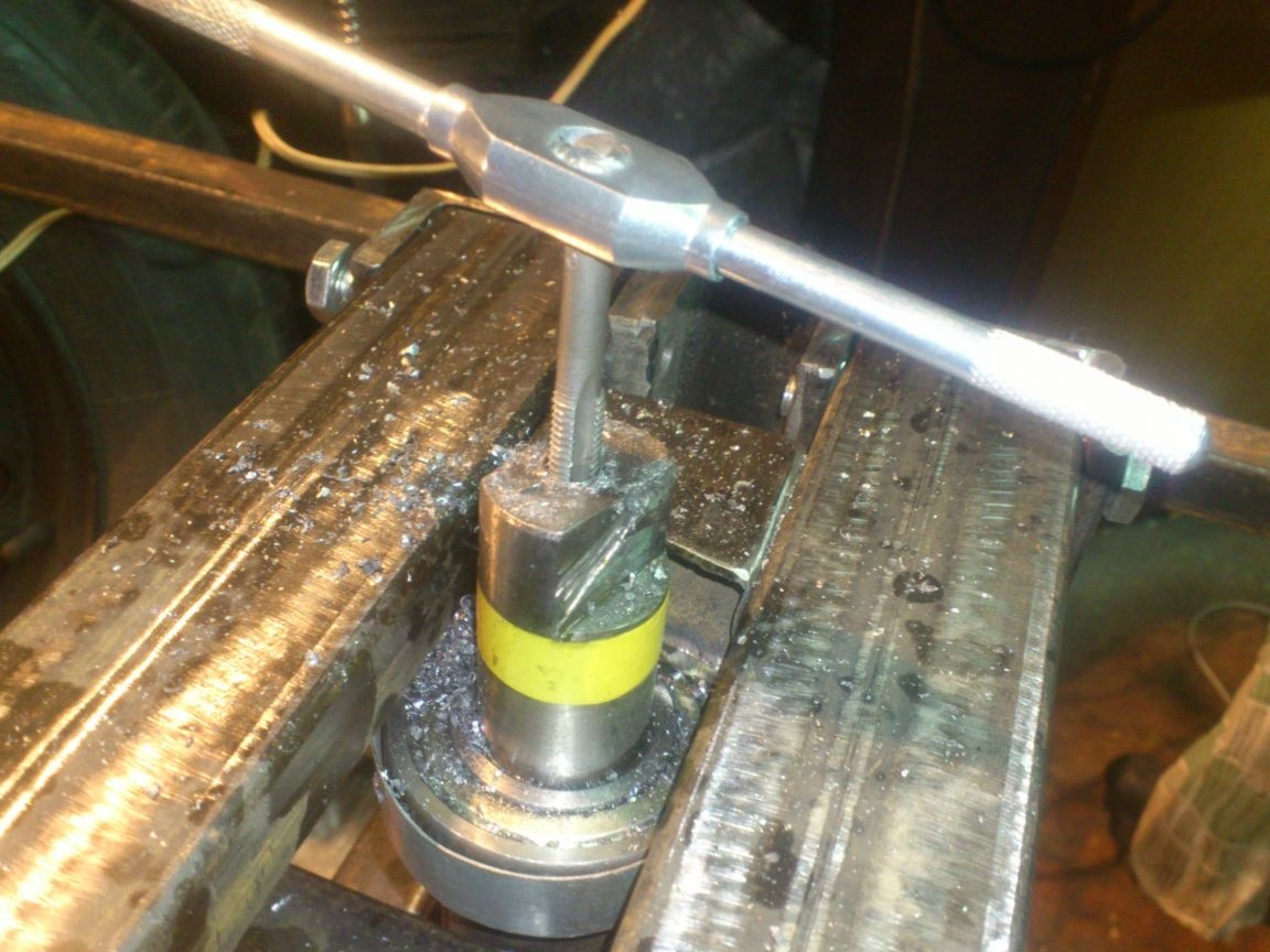
I welded a piece of pipe 20 to 20 on top of the screw. Left it long. I decided that in the process of testing, if it interferes, I will cut it and I will use a removable lever from the pipe 15 to 15, which is inserted inside ... But, looking ahead, I will say that this was not required. The lever really prevents you from twisting the drive handle if you turn it a quarter of a turn (sticks out across the pipe bender). But it turned out that tightening the screw with an interval of half a turn is quite normal.
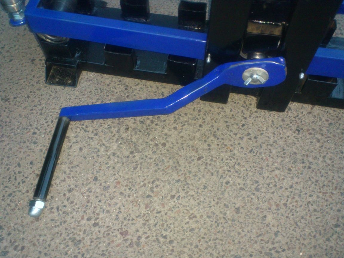
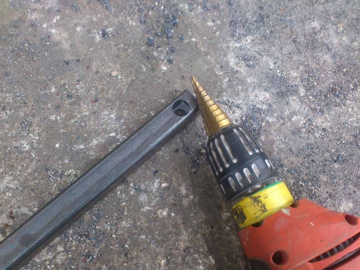
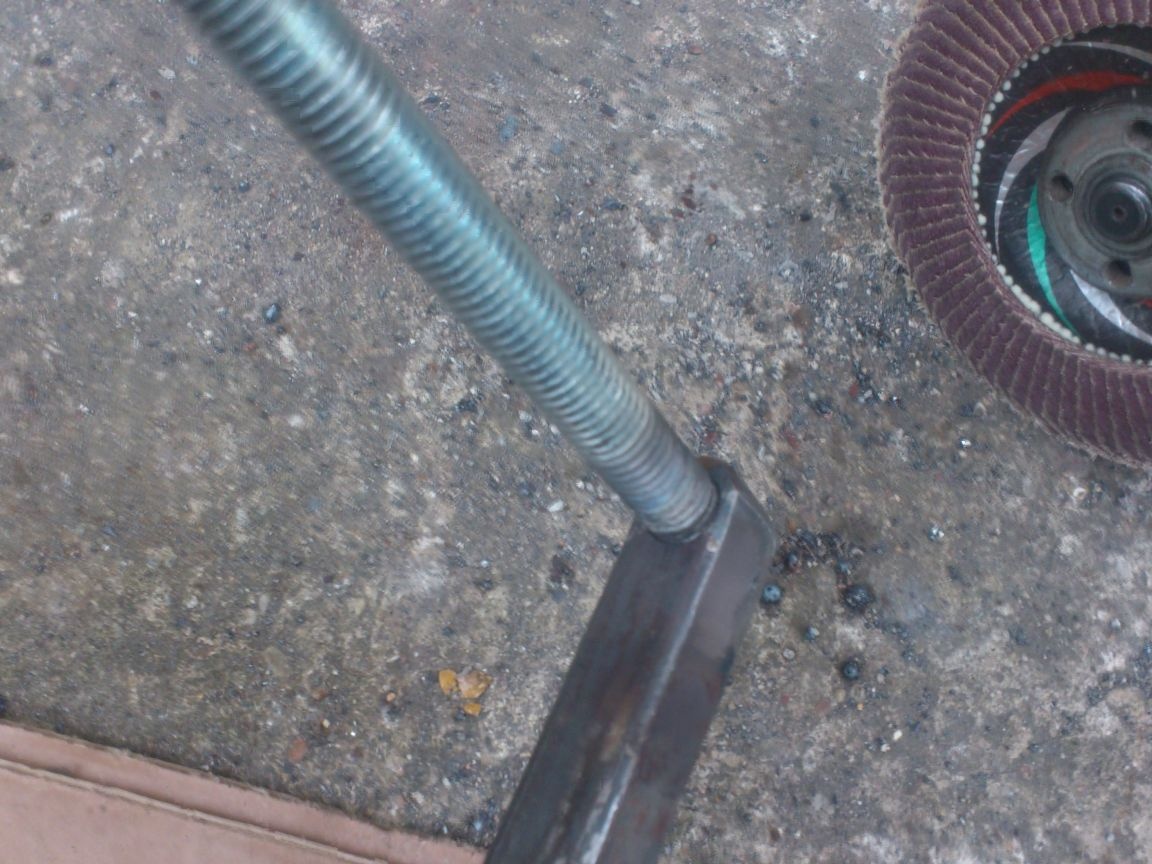
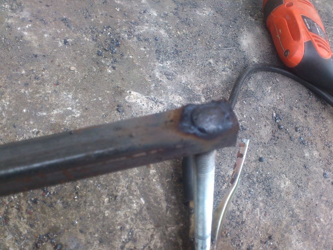
Next, I proceeded to manufacture the drive handle ... I decided to make the handle of the profile pipe 15 by 15 and studs.I drilled a hole at the end, inserted a piece of M14 hairpin into it, welded it and cleaned it:
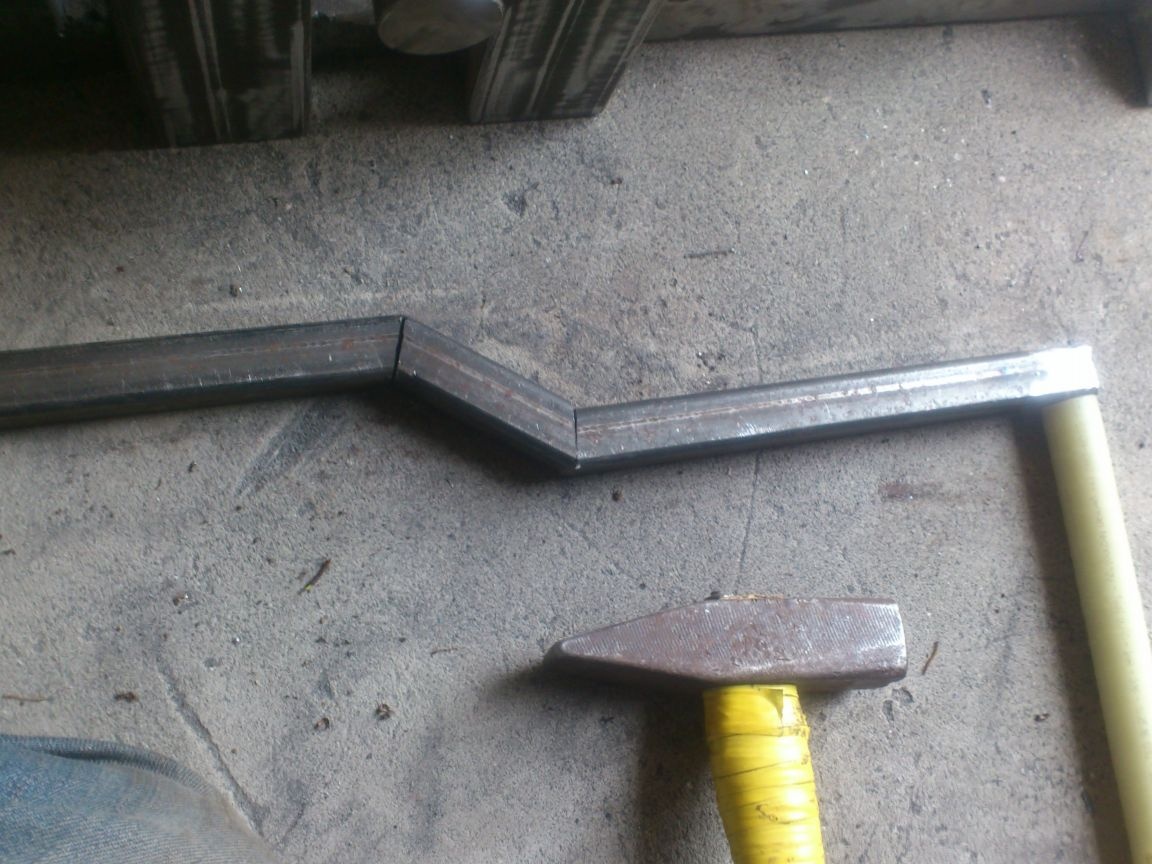
Now you need to bend on the lever itself - the pipe bender will be installed on the edge of the table or workbench.
Next - connect it to the shaft. I decided in advance to make it not only removable, but also so that it turns over and in a transport position does not hang out and cling. On the shaft, I made this profile:
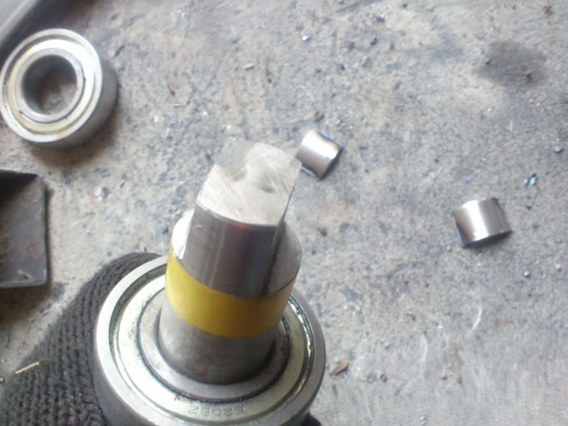
Now you need to make the hub on the handle. I used the corner trim:
Then, as a sculptor, he cut off everything superfluous:)))))
The lever is ready. On the handle itself (which I have made of M14 studs), I simply put on a piece of polyethylene water pipe and tightened the cap nut.
... In general, I want to dwell separately on my use of cap nuts. I often use them if you need an axis of rotation. Having chosen the correct axis length, you can tighten the cap nut and tighten it with maximum force - it rests against the axis with the cap, and will not be easily unscrewed. Of course, it is not worth fixing the axis on which the wheel is located, for example, without cottering, but for "unimportant" axes, such as "curtains" on which something opens and closes, this is quite suitable.
Let's go back to the pipe bender ... As I already said, such a moment as a very simple reinstallation of the shafts was important to me. (Because, knowing, for example, myself, I’m sure I won’t use the option until the last, if it’s difficult to use it ... For example, if the shafts would be close and the pipe would come across with a large cross section, I would try carefully to roll it on this position of the shafts, if for a change you would have to unscrew a lot of some nuts ... And most likely, I would crush it ...). That is why I made mounting locations for bearings from a profile pipe. The shaft is simply inserted into the desired pair of racks.
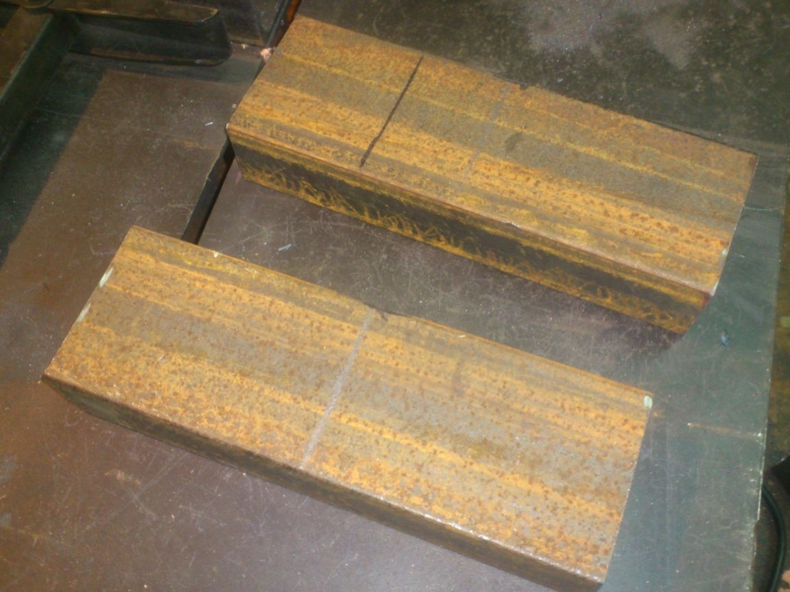
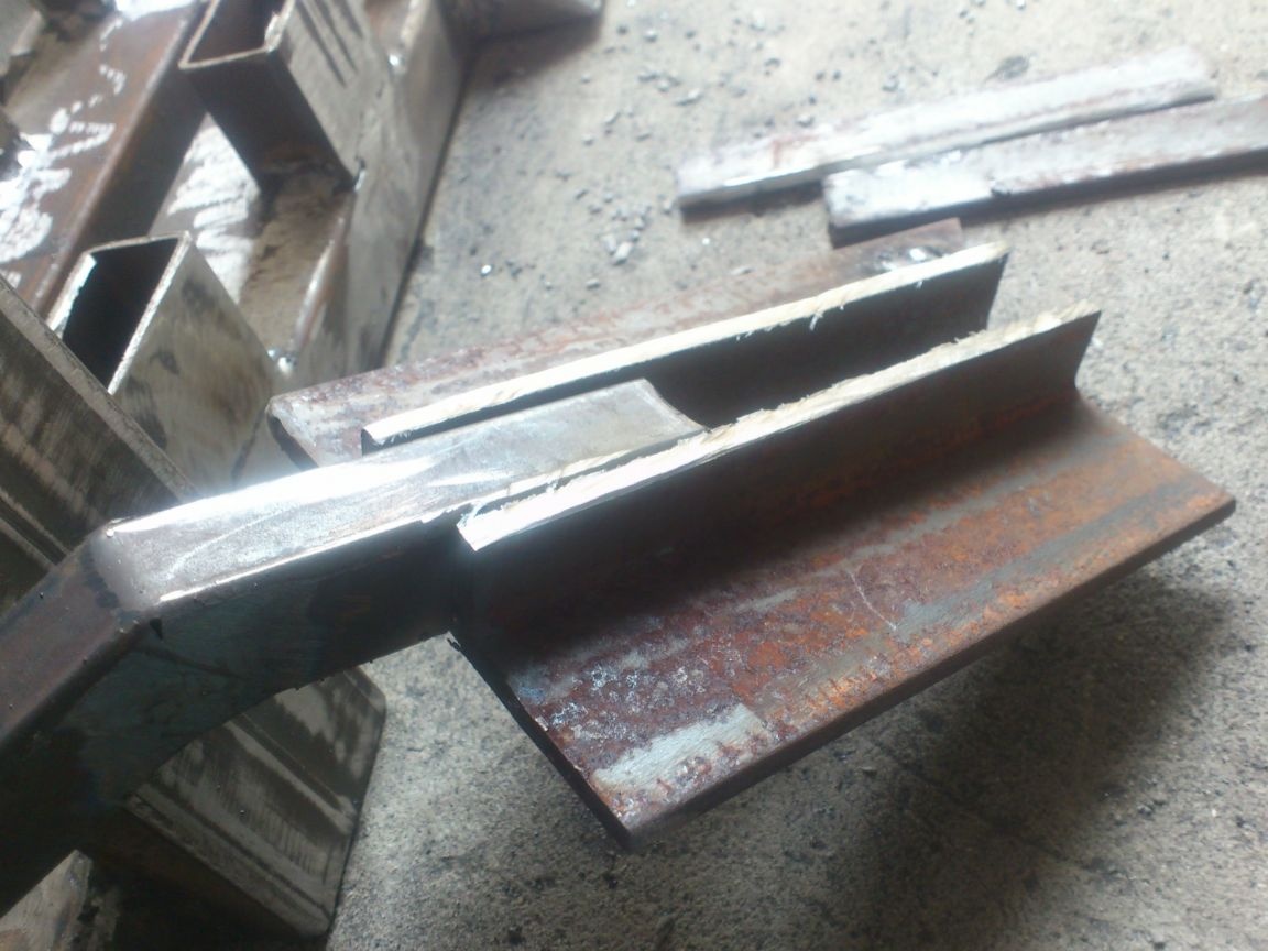
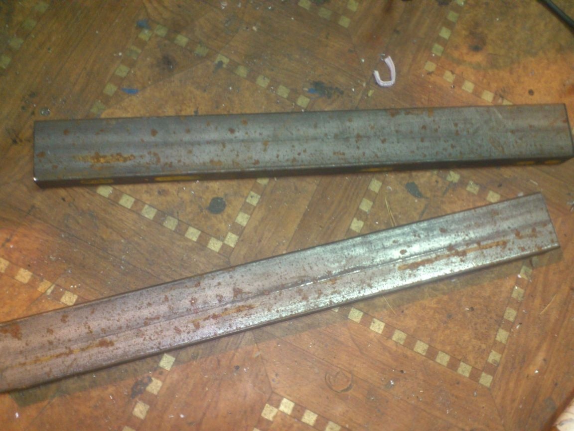
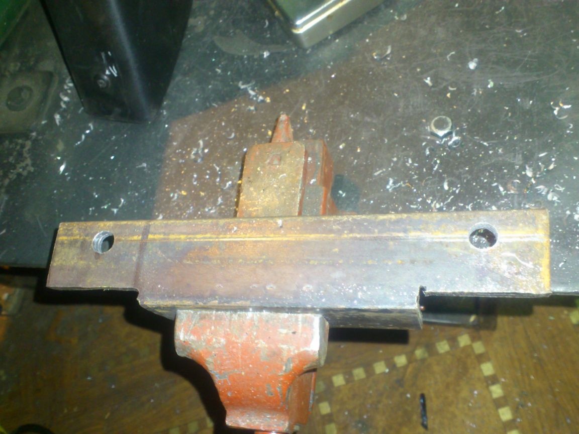
... But this design was contrary to my other requirement - mobility! After all, when carrying the machine, the shafts would have to be removed and transferred separately ... At the same time, the bearings would have to be removed from them (I have drilled it under a loose fit and they can fall off). This did not suit me. Therefore, I decided to make a part that would press the bearings from above and fix them. I took two pieces of a profile pipe, with a section of 50 by 20 mm, a wall of 2 mm.
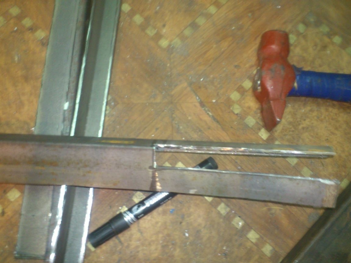
After which I cut them along the wide part, dividing the wall into 10 and 40 mm. At the same time, on the other hand, I marked this size mirrored. I got four such blanks:
Given that the width of the 206th bearing is 15 mm, it fits tight enough into this workpiece.
Measured the required length, I cut the remainder like this:
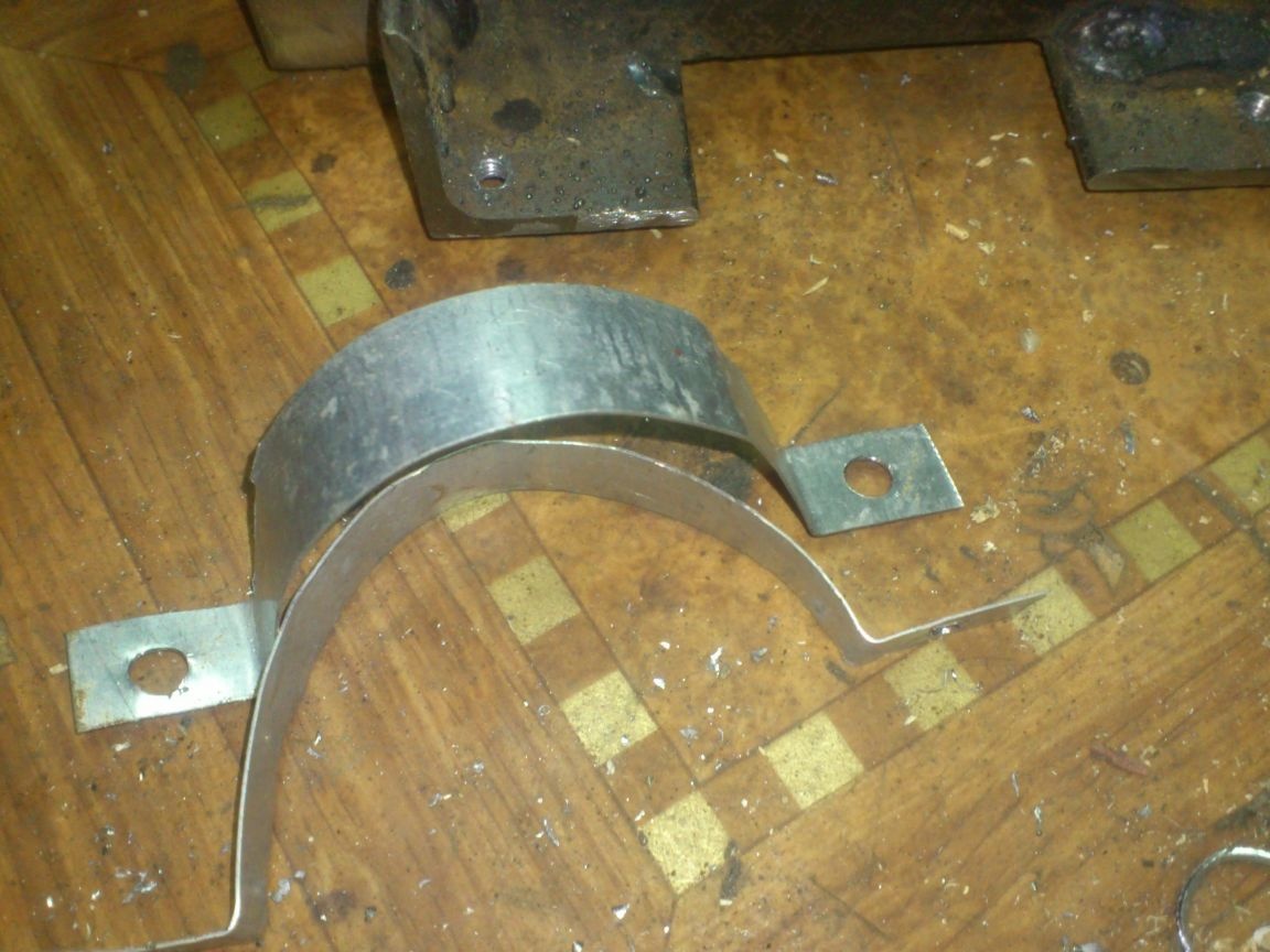
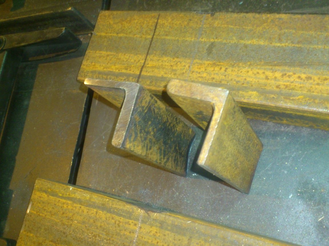
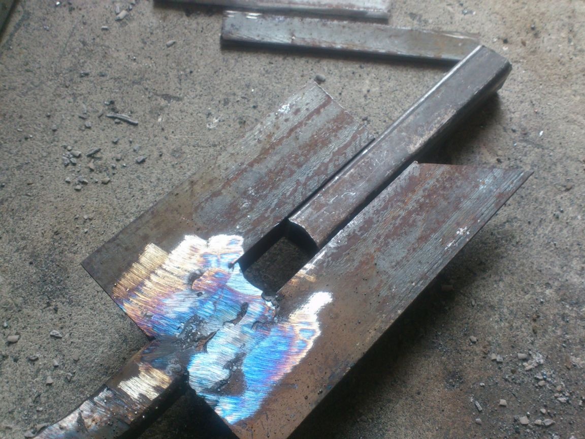
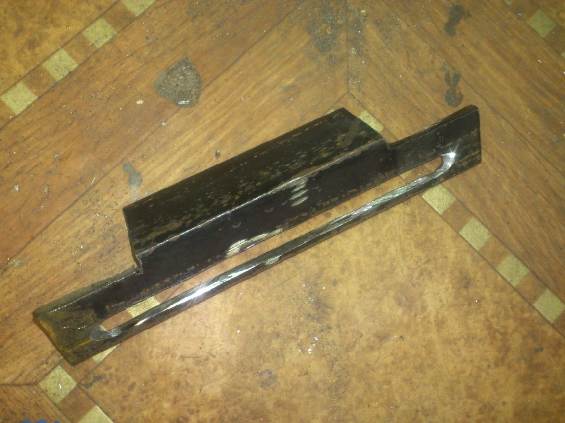
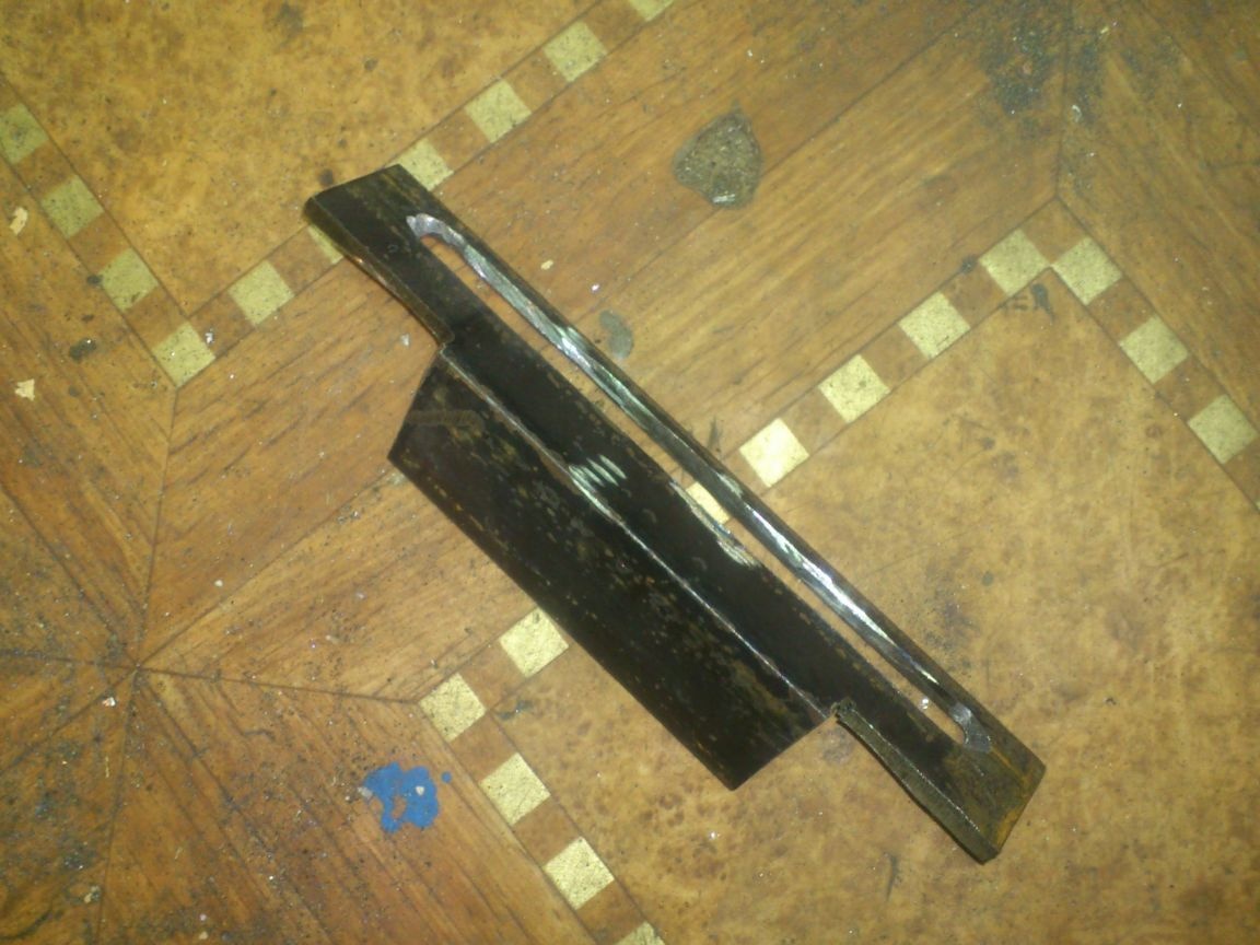
After that, the upper part bent down 90 degrees, making, respectively, washed down the corner:
On them I cut out on such a "tooth":
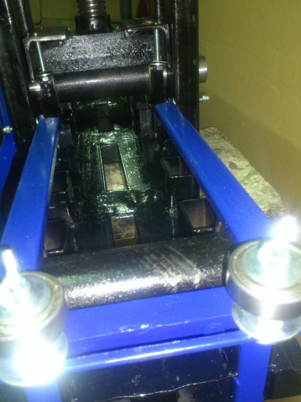
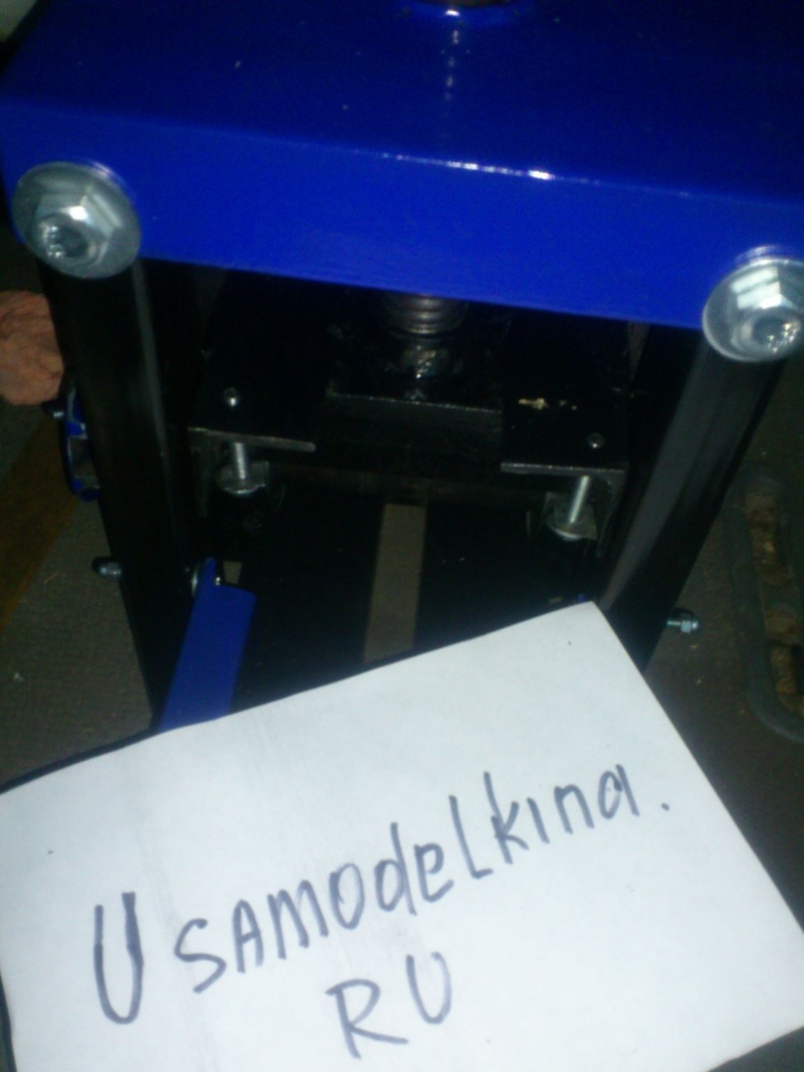
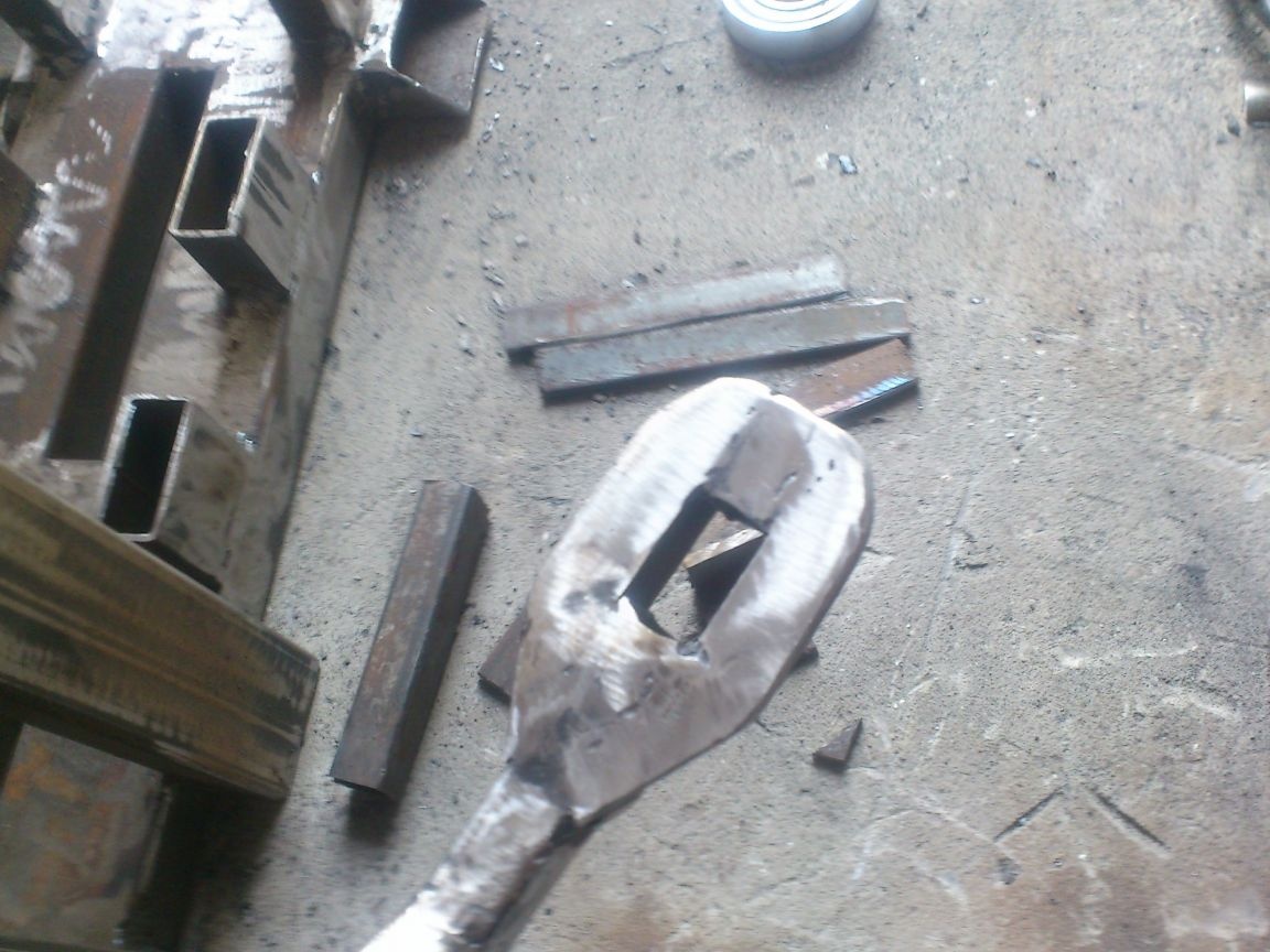
Now I installed both shafts on one side of the pipe bender, put the resulting parts on them, to the vertical posts, drilled through, I fastened them with M4 long screws with cap nuts (the axles turned out). Ahead, I bent towards each other, sticking forward strips of side walls. Now, if they are riveted together, we get a U-shaped cover, which, when lowered down, will cover the shaft bearings and fix them tightly:
In this case, the "tooth" on each side will snap into the end of the profile pipe from which the lower platform is made:
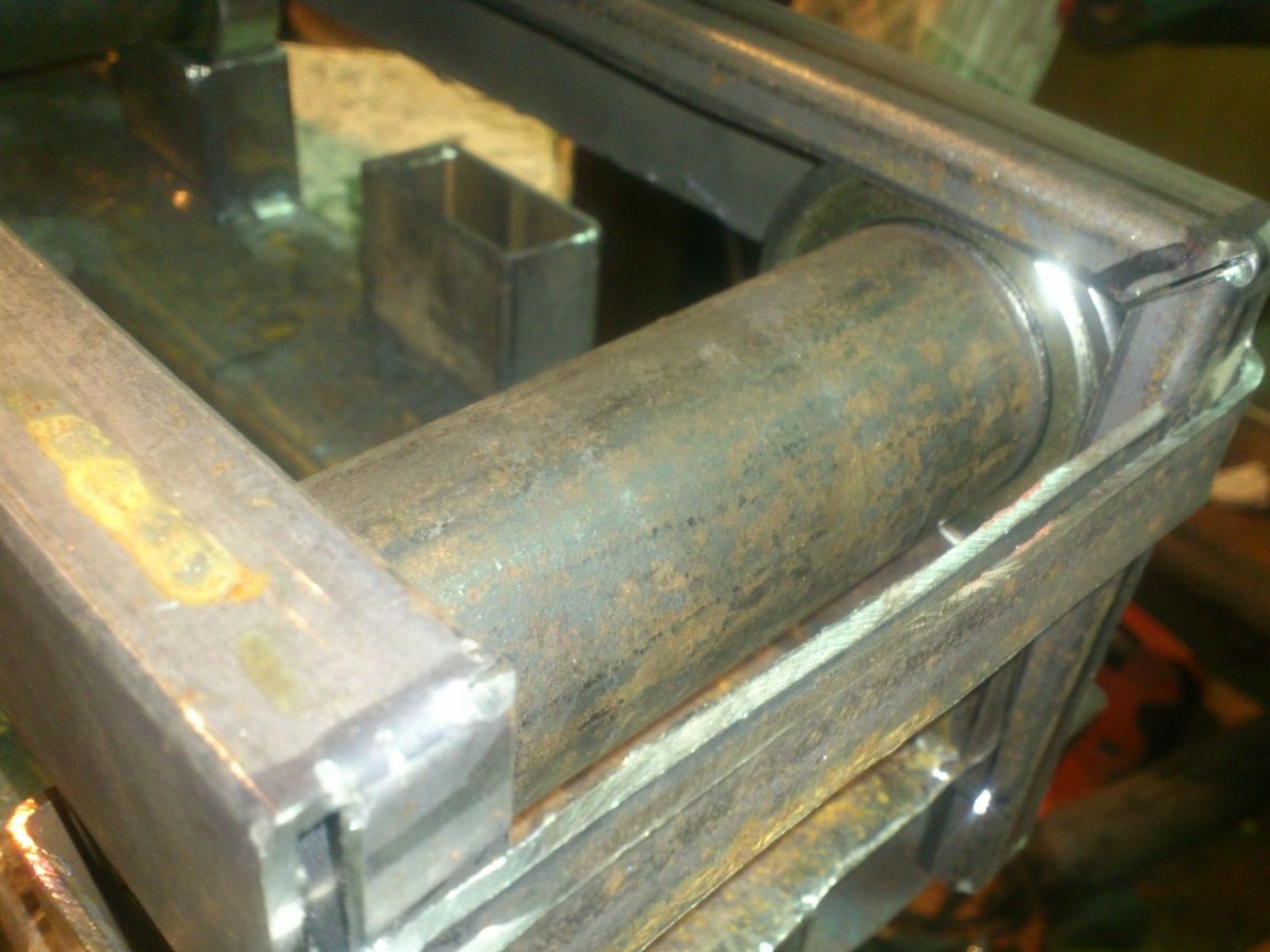
To lift the closure, you need to pull the vertical element with your fingers when the hook comes out of the end of the pipe, you can lift the entire cover up and rearrange the shaft. Then lower the cover and gently press the "hooks".
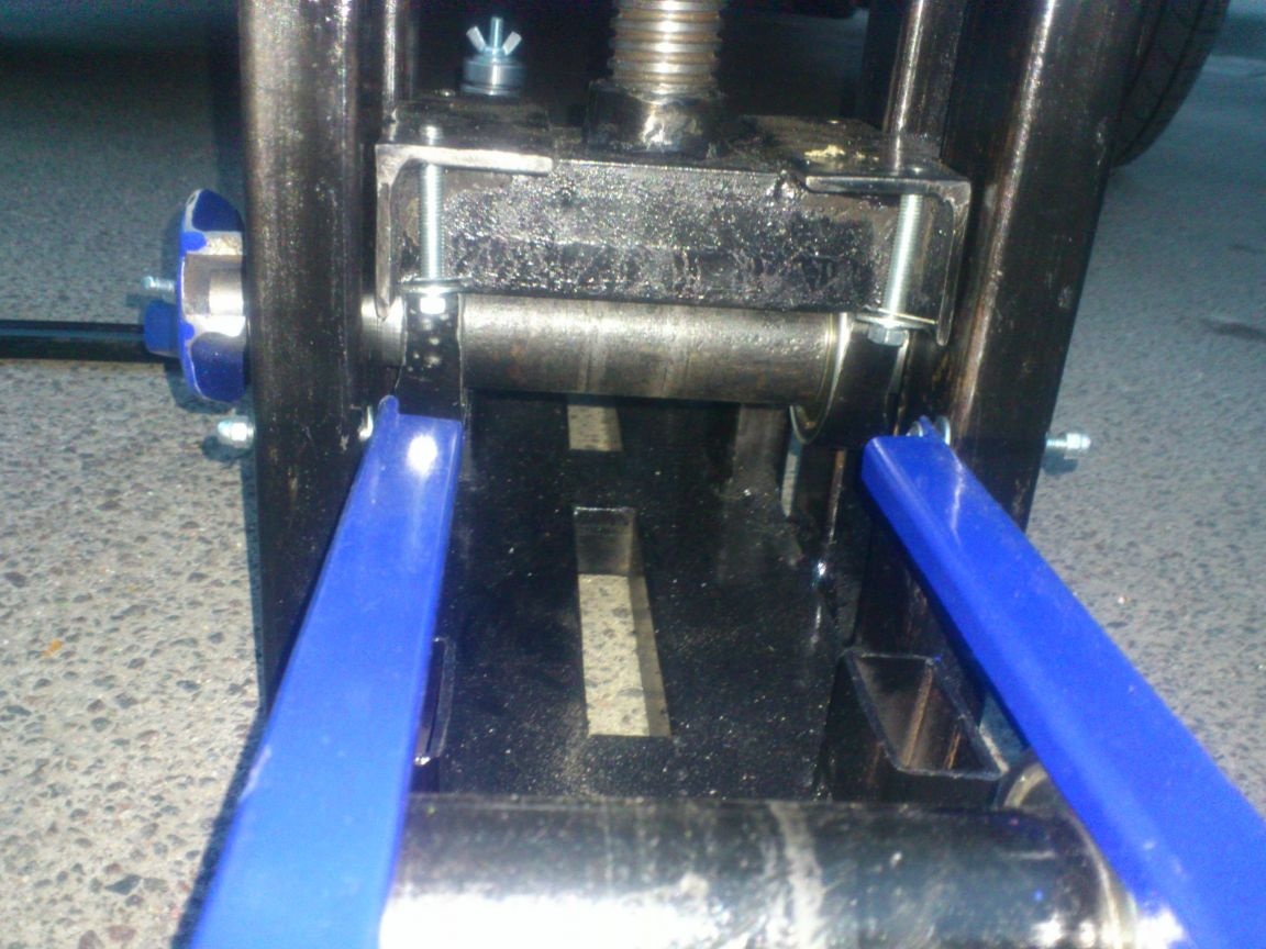
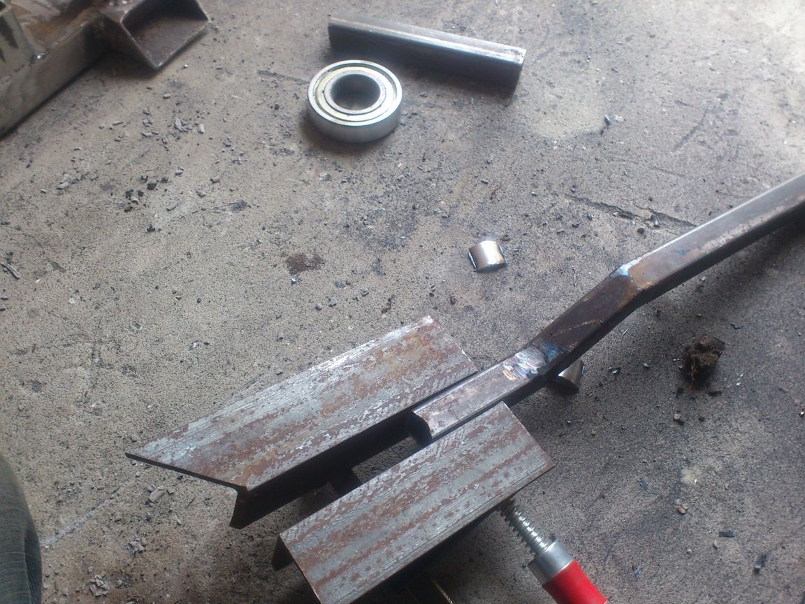
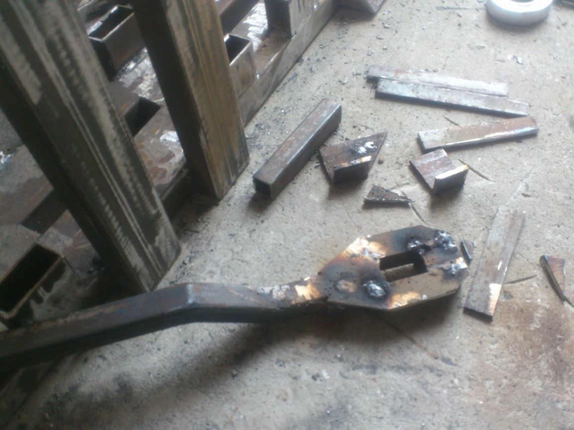
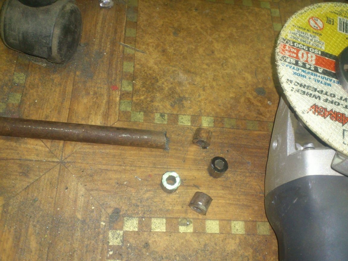
After that, I decided to make stops that would not allow the pipe being processed to go sideways and rub against the sides. For this purpose, it is best to use rings worn on shafts. (That is why I turned the shafts so that the bearings can be easily removed). But at the moment I had neither material of this section, nor access to the machine with the corresponding support, so I made the stops in a different way. I made the following parts of the equal-angle angle 32 mm: 8 mm wide slots:
And fixed them at the ends of my covers.
The limiters themselves were assembled (each) from an M8 furniture bolt, two M10 nuts (put on a bolt purely for height) and two No. 202 bearings. I also stuffed washers inside. I pulled off this whole “sandwich” with the wing nut. Inside the bearings, I inserted a suitable tube by cutting so that they do not hang on the bolts))))):

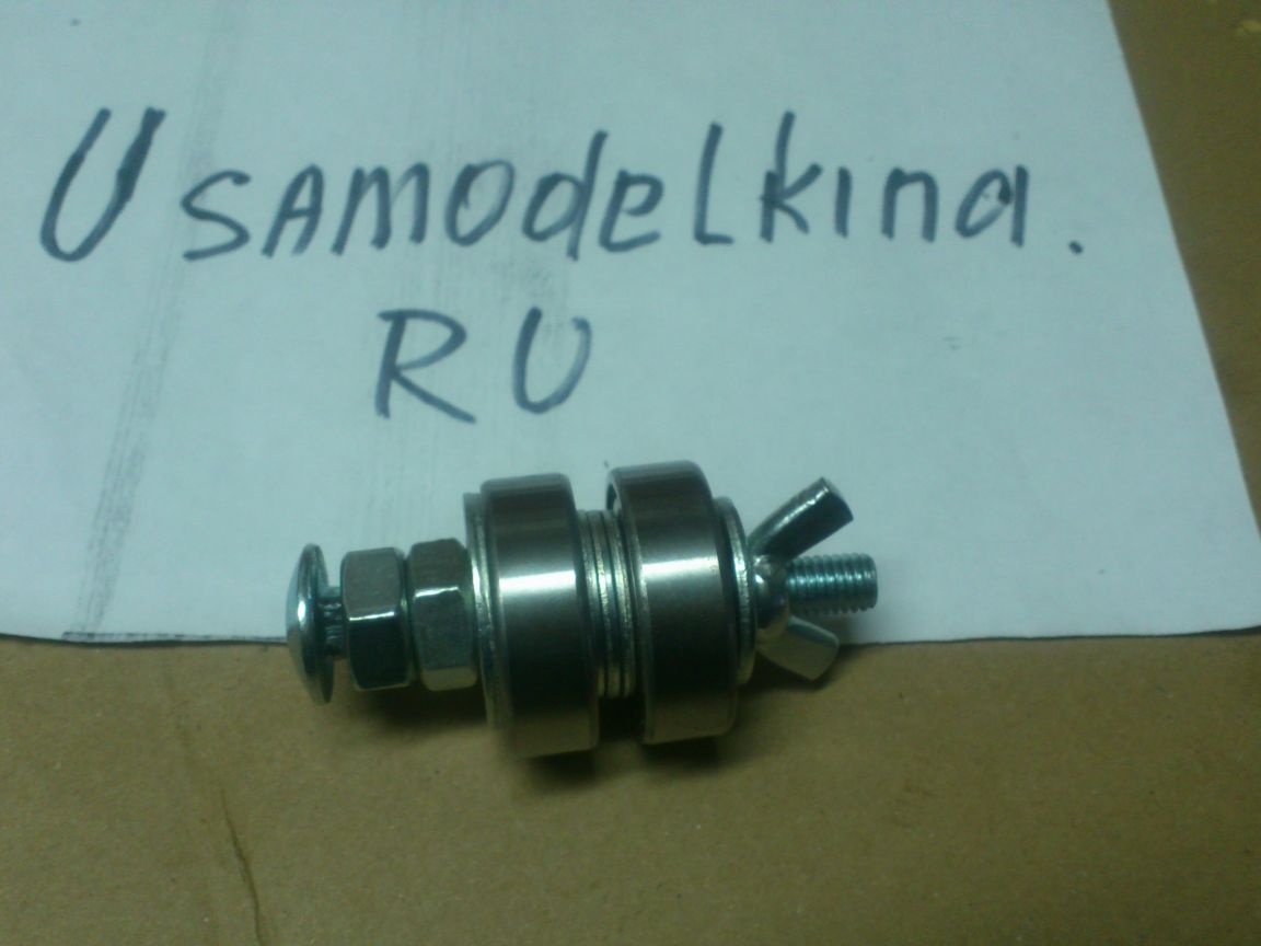
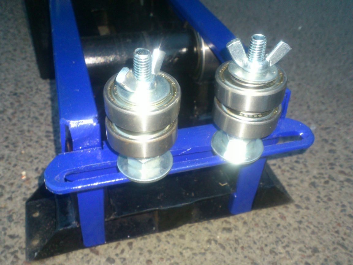
I think their work is clear: if you loosen the nut, you can move the entire limiter along the slot to the desired position, and tighten the nut. The square profile of the furniture bolt under his hat allows you to do this without holding the bolt.
I was afraid that such a device of limiters would not work due to the fact that a pipe, curved by an arc, would rise above them. But, as tests have shown, the height of two bearings and two nuts is sufficient. (At the time of shooting the video, I still did not bend anything to them, so there was one bearing there. After the tests, I took the bolts longer and put on another one). Indeed, when working, it is enough that the workpiece rests against the bearing at least a millimeter and rolls along it. And if I have to roll the pipe in general "in the wheel" (which I did in the tests)))), then this is done in a few calls. And by the time she rises above the bearings, her profile is already leveling, and she does not go aside ....
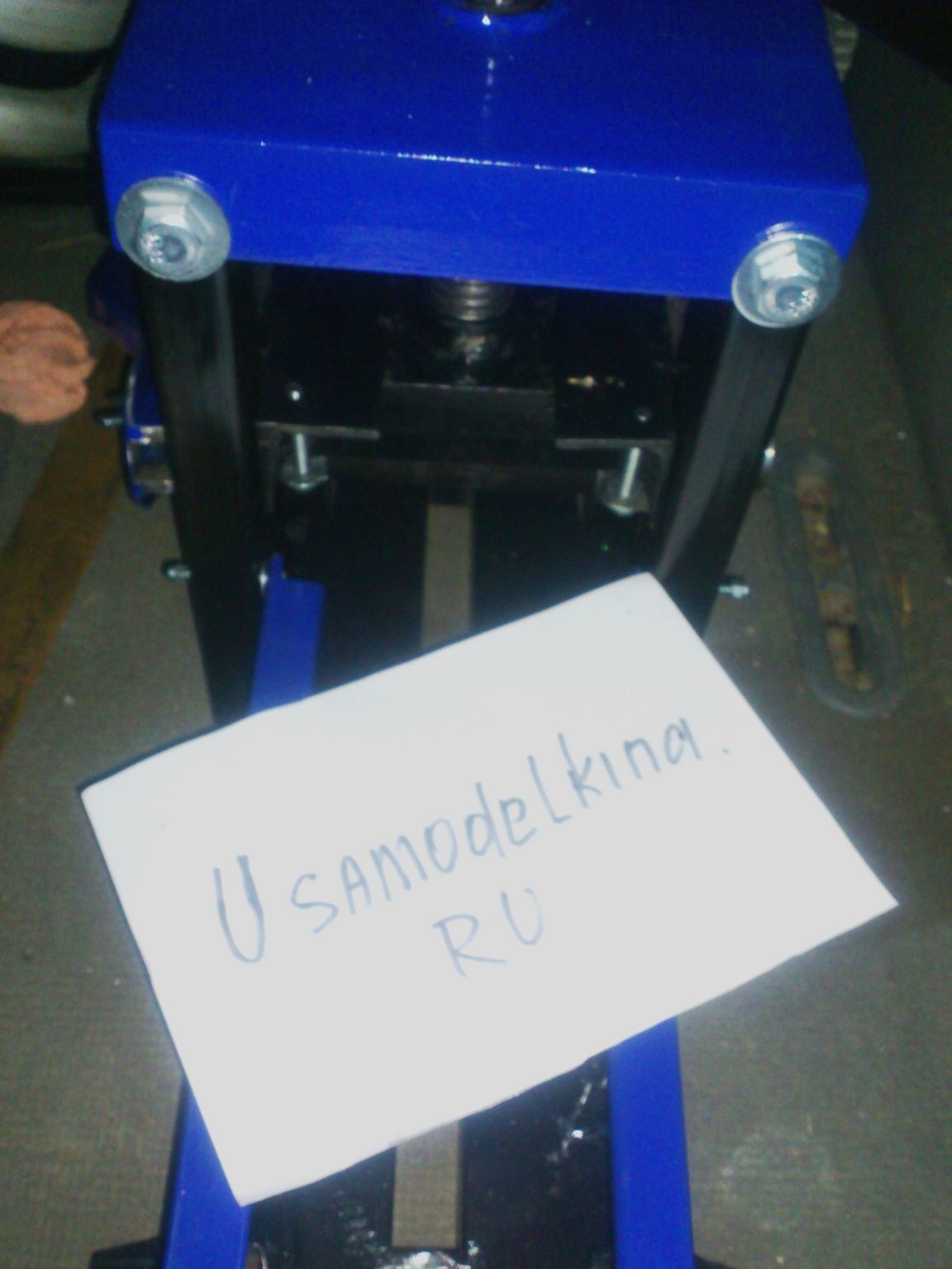
Well, that's all! After painting, I got this little machine: