

The idea of making a wind generator appeared during the early autumn nights. I decided to try to use wind energy for household needs. Let the wind charge the battery, which will illuminate the garden toilet, standing on the edge of the site.
Pulling the power cord to this object is expensive, changing the batteries in the Chinese lantern is tired, and then the free, periodically renewable energy disappears. Since bright lighting is not required at this object, reading books and the press is not planned, then small capacities are enough to solve this problem. In practice, it is a generator with a power of several watts and a small-capacity battery. During the day, the battery is stored in wind energy, and in the dark gives it as needed. For such wind generators, there is practically no point in performing complex calculations and manufacturing special blades. The simplest designs will work perfectly. All this greatly simplifies and reduces the cost of the wind generator, there is a sense of its manufacture and use.
For use as a low-power wind generator, you can use a ready-made stepper motor. For maximum performance, if possible, it is advisable to use an engine with the smallest possible sticking of the shaft (they have such an unpleasant effect) and with as many steps as possible per revolution.
A variant of altering the electric motor into a generator is possible. Various rework options are described on the Internet.
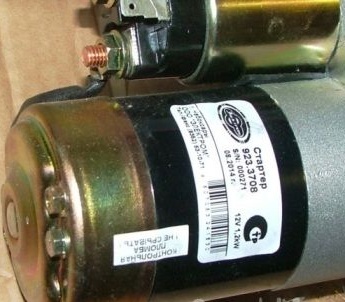
In our case, the option of remaking a used starter 923.3708 from the legendary Oka was chosen.
The use of this starter is due to the following factors:
• small dimensions and starter weight;
• the starter is driven by permanent magnets;
• simplicity of alteration in the absence of investments for the manufacture of the generator.
The process of converting a starter into a generator
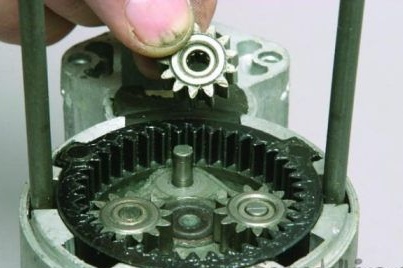
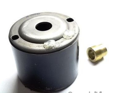
1. Disassemble the starter: Disconnect the power cord and remove the parts of the traction relay. We release and remove the housing and shaft of the freewheel, built-in planetary gear.
2. Carefully remove the brush assembly cover. At the same time, we monitor the safety of the support ball in the cover bearing.
We disassemble and remove the brush assembly. We remove the rotor. Three nodes remain for future use.
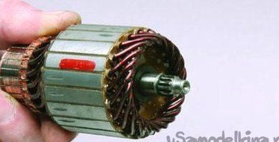
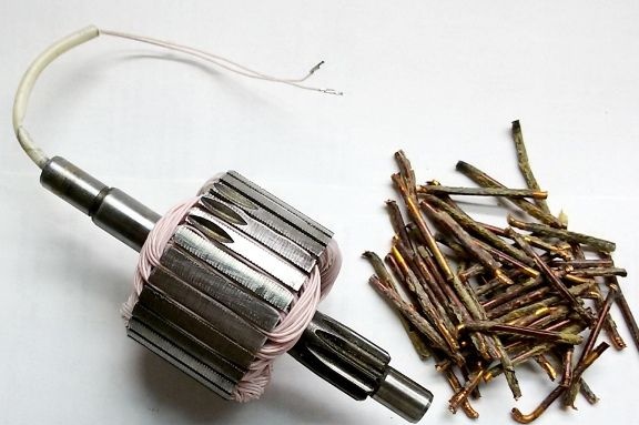
3. Using nippers and pliers we remove the old winding of the starter rotor. Mechanically remove the rotor manifold.We clean the shaft and the grooves on the rotor plates from the remnants of varnish. In the photo, to the right of the new rotor, the remains of the old winding.
4. We perform mechanical processing of the rotor
a. On a lathe or manually remove the slots for connection to a planetary gearbox and get the landing diameter for the second sliding bearing.
b. Between a set of rotor plates and a machined area, half the diameter, we drill a radial hole with a diameter of 4 mm. The hardness of the shaft is negligible and is available for processing with high-speed tools.
c. On a lathe or manually with a drill, on the part of the treated area, we drill an axial hole with a diameter of 4 mm, until it matches the radial. We get a hole for outputting the rotor winding. This output circuit allows you to abandon the sliding contacts for the removal of current and increase the reliability of the generator.
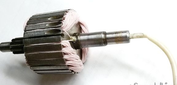
For clarity, the location of the holes and the output of the winding are shown on the finished rotor.
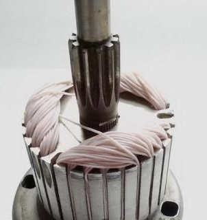
5. We wind the coil winding into the grooves of the rotor, until it is full. The arrangement of six permanent magnets with alternating poles in the stator determined the location of the winding coils.
The width of each coil (5 grooves) was determined by the distance between adjacent magnets. The turns of each of the coils located opposite in the adjacent grooves, when the rotor rotates, simultaneously intersect the magnetic field of two magnets with different poles. In this case, the induction current in the coil is added. Three similar groups (5 coils each), the coil - magnets, work simultaneously. All coils are connected in series and complement each other. Changing the pole of the magnet relative to the coil, during rotation, gives an alternating current. Since the rotor has 31 grooves, 1 groove remains free.
To avoid damage to the insulation of the wire during winding and operation, a multi-core MGTF wire with a core diameter of 0.30 mm was used. It is possible to use another insulated wire.
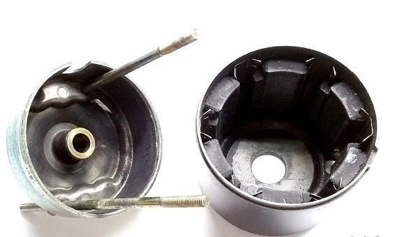
6. Due to the absence in the used part of the starter of a second bearing for the rotor (one is in the cover of the brush assembly, and the second remains in the removed planetary gear), we will manufacture a new bronze sliding bearing. The outer bore diameter of the bearing is determined by the diameter of the hole in the baffle plate (photo below), and the inner diameter of the bearing and the length of the outer steps - the actual diameter and length of the machined section of the rotor shaft (p.4a).
7. Install the manufactured bearing in the housing, and the saved ball on the bottom of the bearing in the cover.

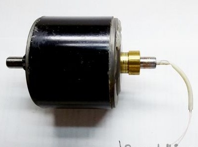
8. Install the machined section of the rotor in the manufactured bearing and assemble the rotor with the housing. Before assembly, lubricate all the rubbing parts.
9. Install the cover of the brush assembly by aligning the second support of the rotor shaft with the cover bearing and the support ball. We combine the holes of the body and the cover, install the mounting studs from the kit.
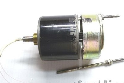
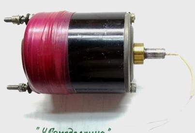
10. We assemble the generator. The free end of the rotor shaft (with the output of the winding) is used to install and secure the generator. On the free part of the studs (above the cover) we will install a rotor-type wind wheel.
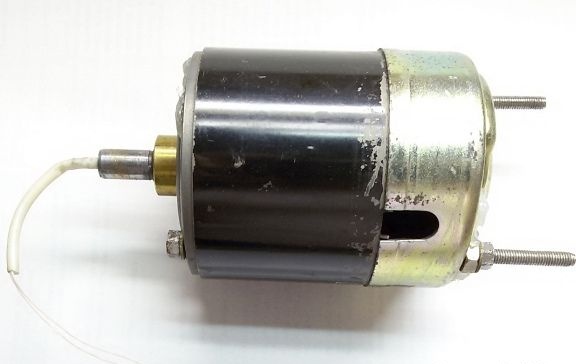
11. To protect the inside of the generator from dust and moisture, close all open holes with hot melt adhesive. For testing, additionally sealed the joints with electrical tape.
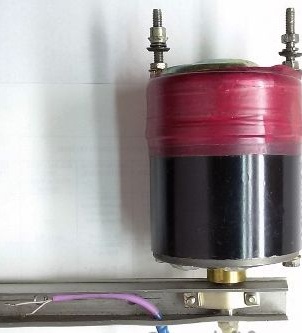
12. We make a support for installing the generator on the object.
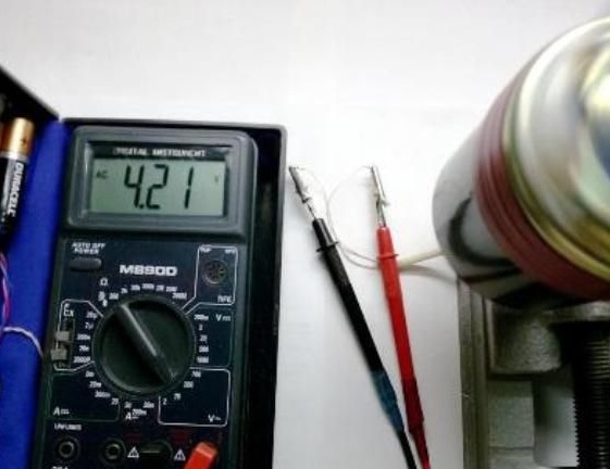
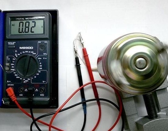
13. We measure the output of the generator at medium speed (rotation by hand). The generator gives a voltage of 1 ... 5 V and a current of 0.2 ... 1.1 A.
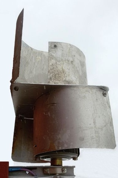
14. For testing a wind generator, a rotor-type turbine is manufactured.
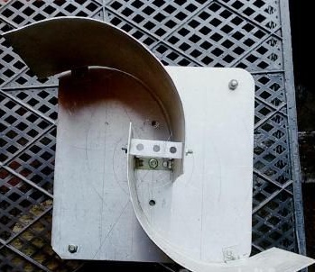
The advantages of a rotary wind turbine:
• With a gusty wind, rotor windmills have greater stability in operation than screw propellers.
• Silent and work, no matter where the wind blows.
• Shaft rotation is more stable, without sudden jumps in speed.
• ease of construction;
• ease of manufacture and installation.
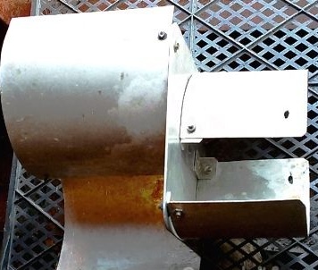
15. The appearance of the wind generator.