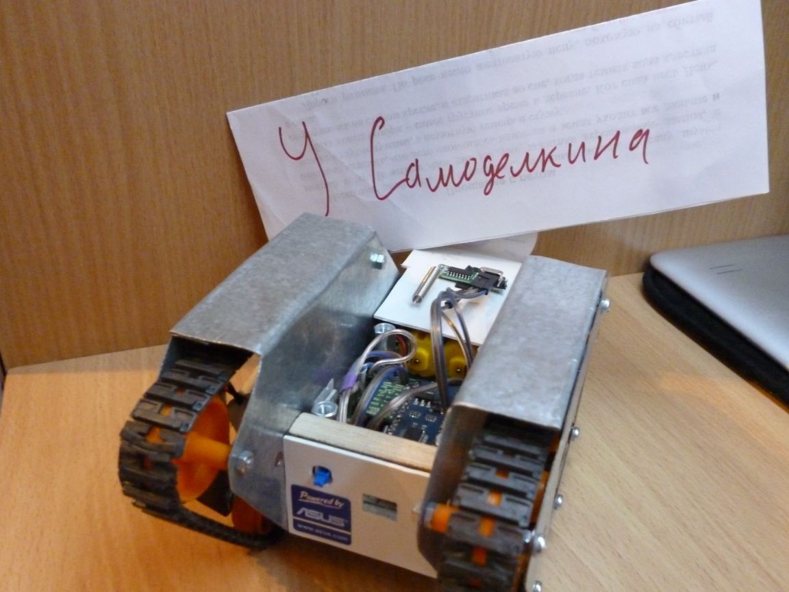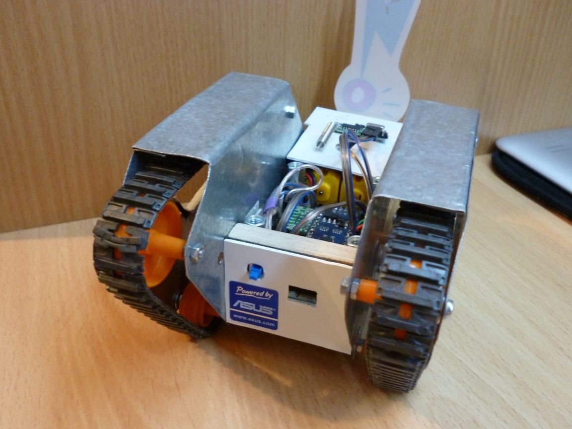
I continue to upgrade my chassis and provide instructions to you. This time I will connect a 433 MHz radio module.
To implement this homemade need to make a chassis. The detailed manufacturing process described here:
Tracked chassis
According to these instructions, you can connect the 433 MHz module to another chassis or device based on Arduino.
We start the manufacturing process, we need:
- Universal chassis or device on Arduino
- 433 MHz radio communication module (or its clones)
- Any Arduino board (for control)
- Connecting wires "mother - mother"
Step 1. Choosing a module.
In fact, a data transmission device consists of two modules: a receiver and a transmitter. Data can only be transmitted in one direction. This is important to understand when using these modules.
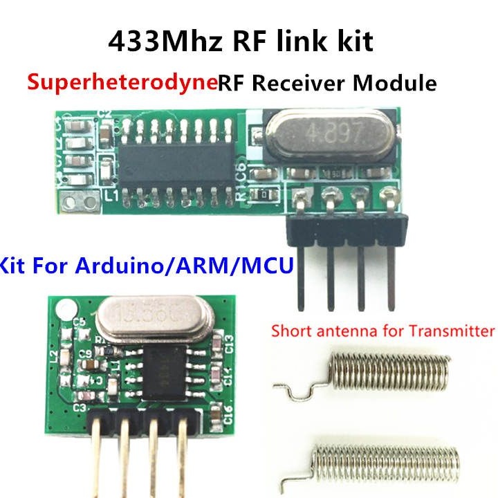
Modules can have different names: MX-05V, XD-RF-5V, XY-FST, XY-MK-5V, etc., but they all have approximately the same appearance and numbering of contacts. Also, two frequencies of radio modules are common: 433 MHz and 315 MHz. I will use 433 MHz, but the same thing can be done with the module at a different frequency.
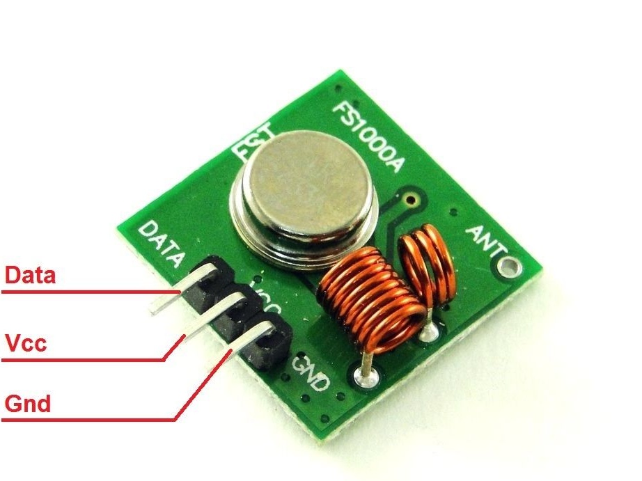
In order not to get confused: a small square board is a transmitter, a larger rectangular one is a receiver.
Transmitters may look different depending on the version:
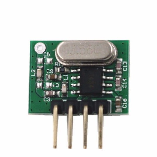
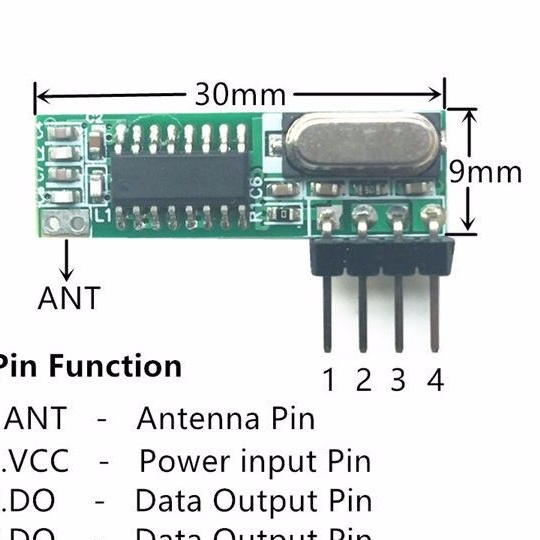
And here is the receiver:
Step 2. Solder the antennas
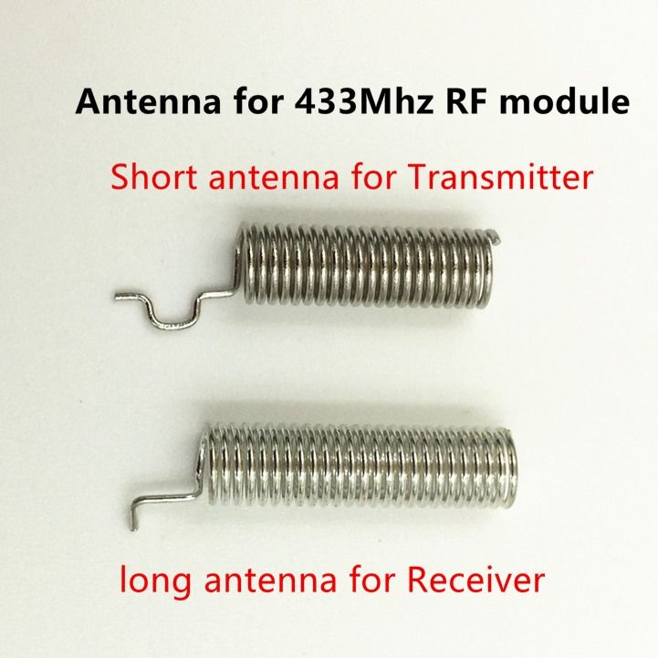
The first amplifier of any receiver and the last amplifier of any transmitter is an antenna. The simplest antenna is a whip antenna (a piece of wire of a certain length). The length of the antenna (both the receiver and the transmitter) should be a multiple of a quarter of the wavelength of the carrier frequency.
Antennas almost always come with modules. They are soldered to the pads.
We attach the short antenna to the transmitter, long to the receiver.
Step 3. Connection.
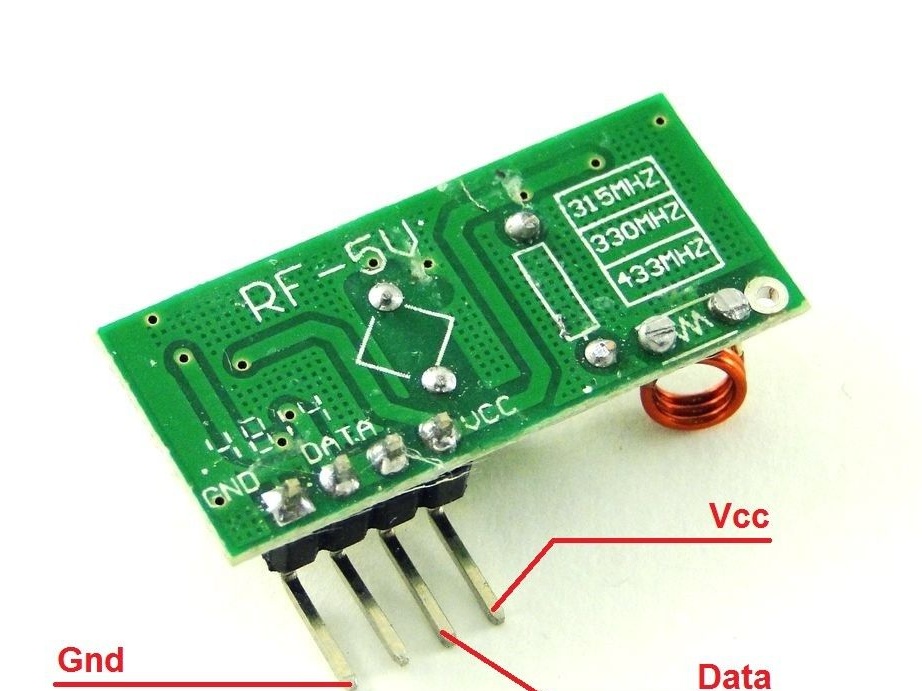
The transmitter has only three outputs: Gnd, Vcc and Data. It must be connected to any Arduino board that will be used as a transmitter. Making a complete remote control is beyond the scope of this article. Next time I’ll write the instructions for making such a remote control, but for now we’ll just use the board. Wiring diagram:
Vcc - 5v
Gng - Gnd
Data - D2
The receiver has four outputs, but one is not used. Glue the broom on a double-sided tape and connect it to the chassis.The connection diagram is identical to the transmitter:
Vcc - 5v
Gng - Gnd
Data - D2
Step 4. Firmware
In my opinion, it is most convenient to write firmware in the Arduino IDE. The current version at the time of writing is 1.8.2. There are several libraries for working with the radio modem. We will use the RCSwitch library. In my opinion it is the most comfortable.
So, we record the scratch in our chassis.
== ask 433 Uni
If you use another chassis, then the scratch needs to be corrected; it is written for my universal chassis.
In arduino with this transmitter: