

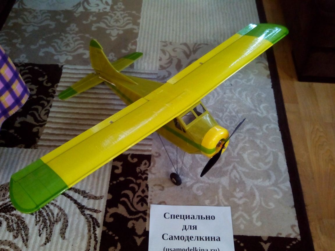
This article will be a detailed description of the construction of the Canadian Beaver model aircraft. This model well suited for beginner model aircraft in terms of creation and in terms of management. Materials and tools were chosen the most affordable, so almost anyone could assemble such an airplane. In addition, he made small changes in order to simplify the construction process.
Materials:
- Laminate flooring
- Ceiling tile
- Wooden rulers
- Tin
- Threads
- Glues (PVA, epoxy and ceiling)
- Scotch tape
- Bolts and nuts
- Steel wire and knitting needles
- Bamboo sticks
- sticks from balls
- Pieces of thin transparent plastic
- Plastic cards
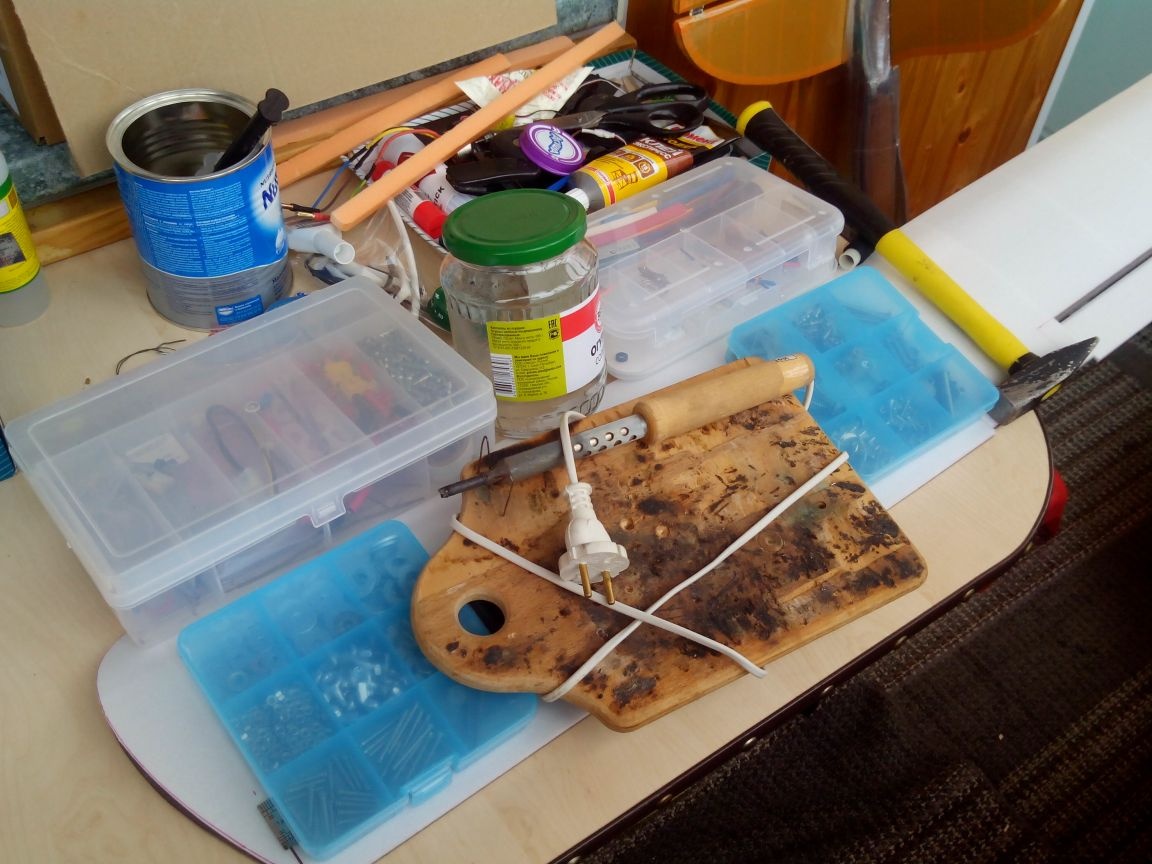
Instruments:
- Cutter
- Jigsaw
- Sandpaper
- stapler
- Marker for disks
- Ruler
- scissors
- Thermogun
- Soldering iron, solder, flux
- Iron
- awl
- Needle files
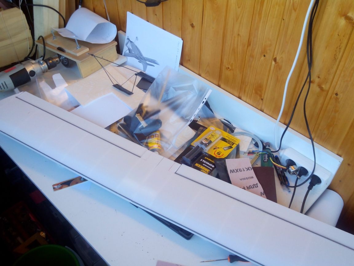
Electronics ():
The motor - in the photo below, the engine is different from the purchased model (there is no marking), but the engine by reference is practically its analogue, only the screw is fastened with a collet clamp, and not on the thread.
Tsang -
Servos -
Wheels - and
Drawbar clamps -
Wild boars -
Speed control -
Propeller -
Batteries -
Equipment - any on 4 channels and more
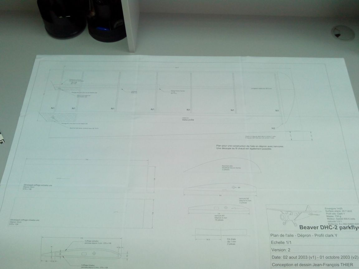
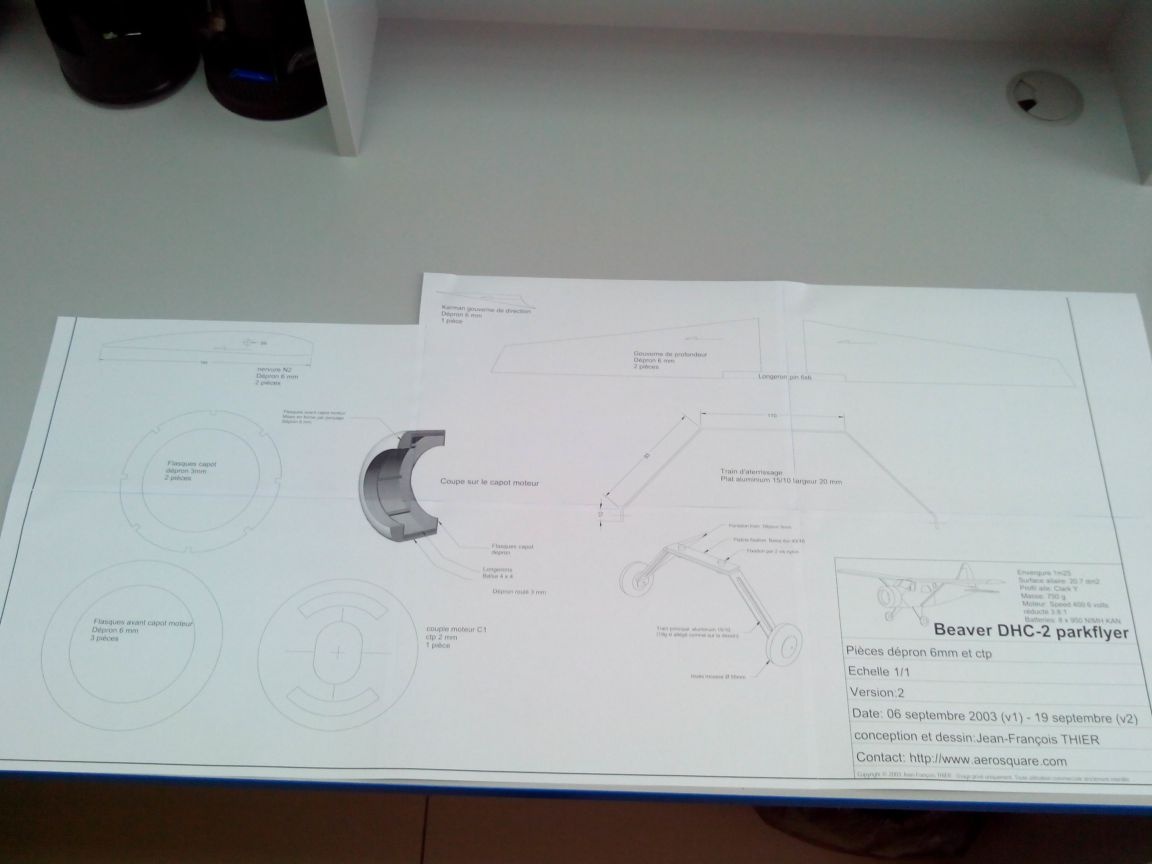
Step 1. Drawing
Drawings of this model can be downloaded in two formats: and.
After the drawings are printed, proceed to gluing them.
Wing:
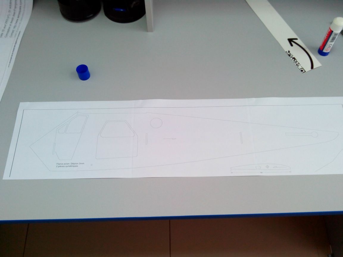
Fuselage:
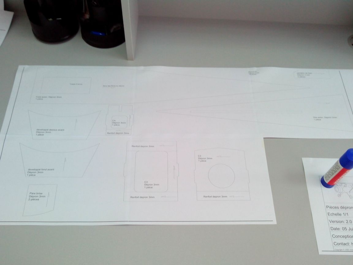
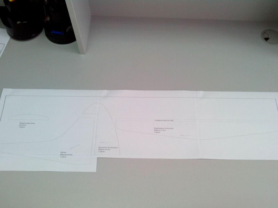
Hood, chassis and tail:
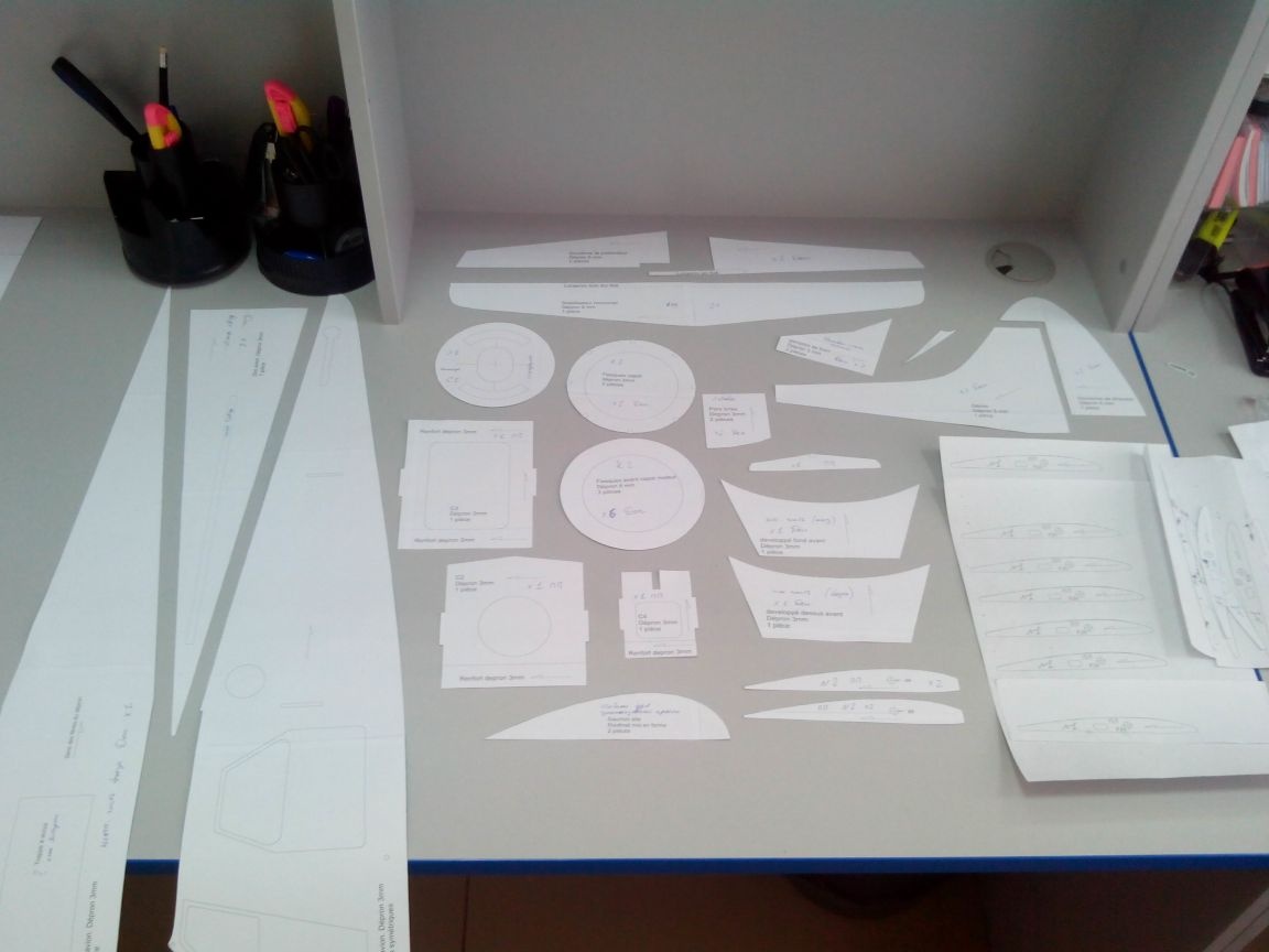
Then we cut out the templates of all the parts (except for two rectangles in the wing drawing - they are not life-size!)
Step 2. Wing
We start making the wing with ribs. We print out the required number of templates and glue them to the sheet of ceiling tile.
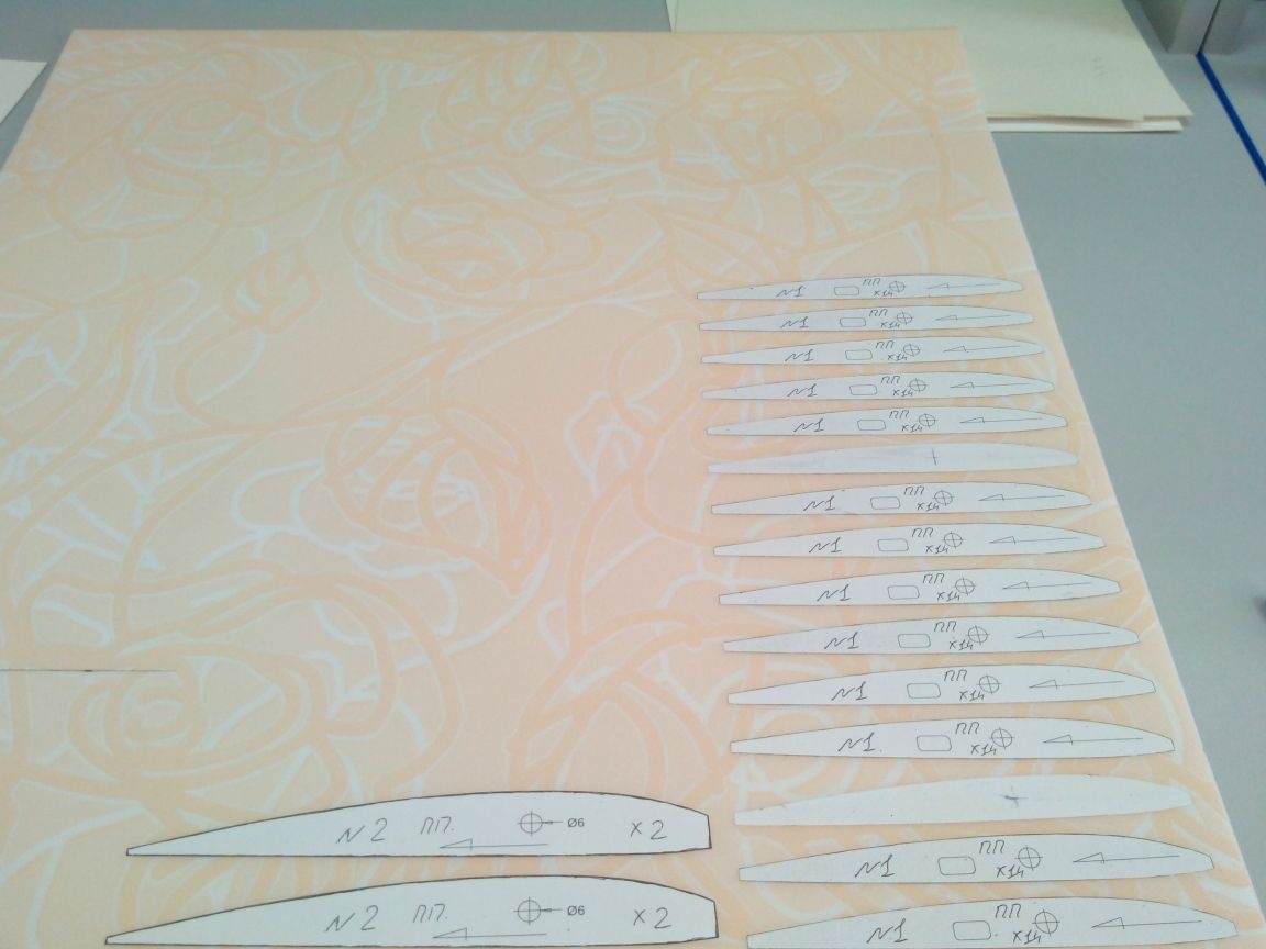
I hurried a bit and did not think up my manufacturing option, and therefore made ribs No. 2, but they were not needed in the future, as I decided to simplify the wingtips a bit without resorting to very dusty processing of pieces of foam.
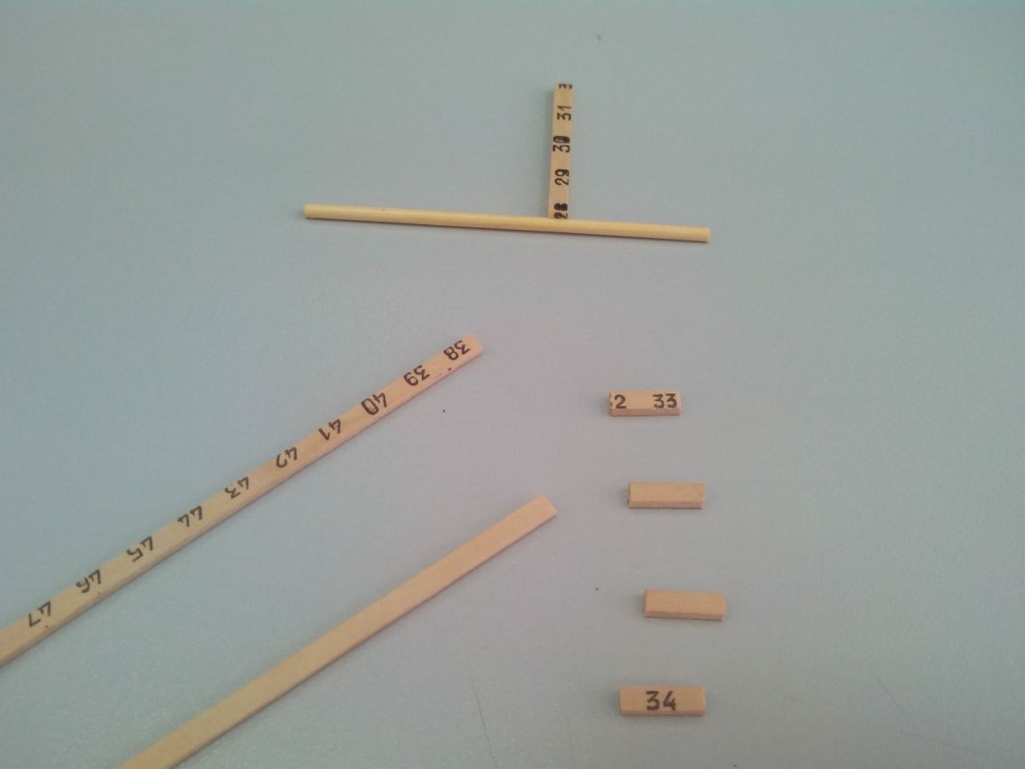
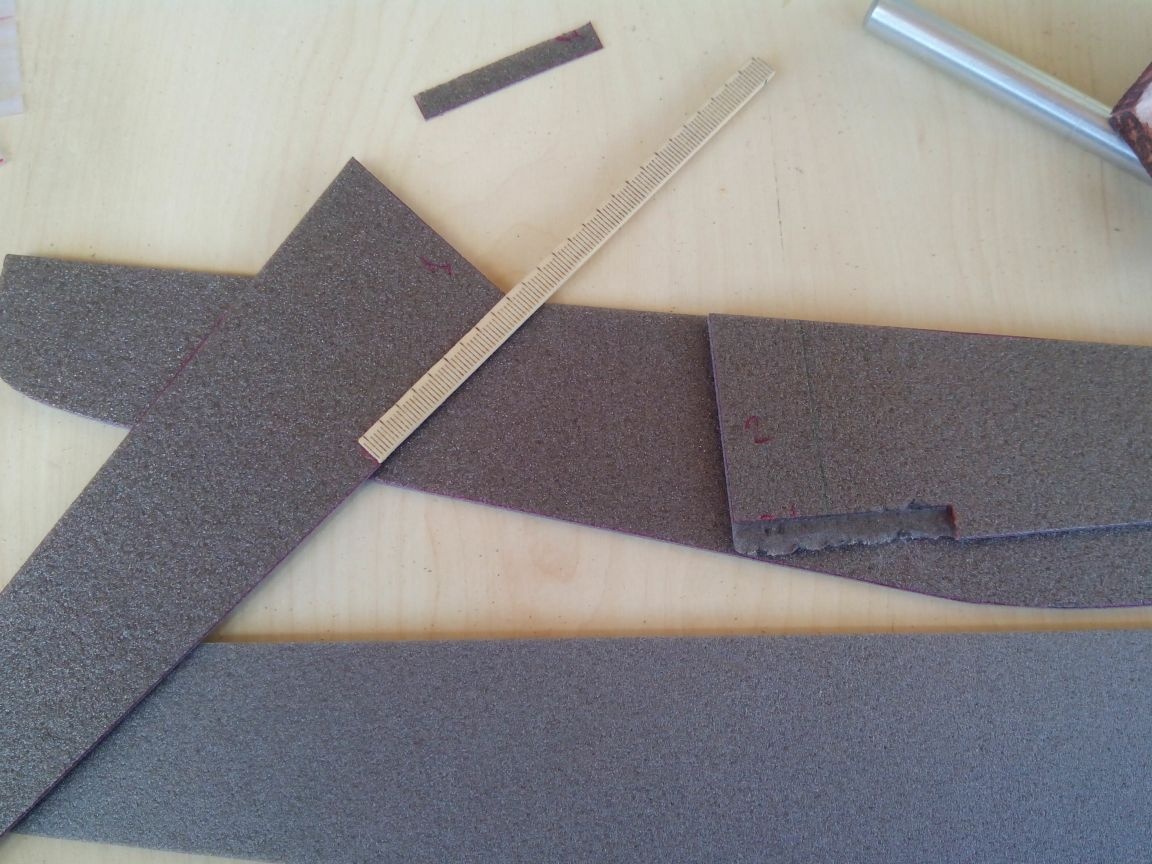
From a wooden ruler (50 cm) we cut 4 slats 6 mm wide.
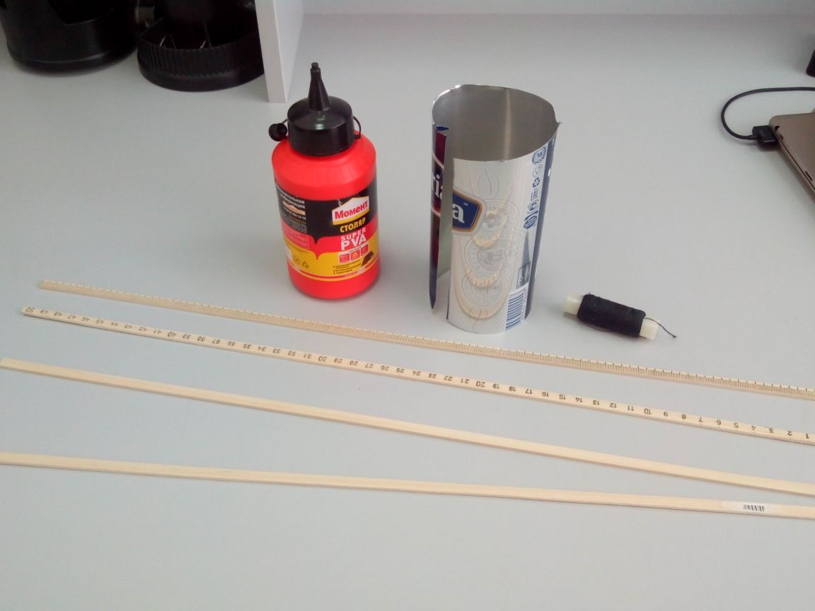
From a can (beer or canned food) we cut three corners according to the drawing.
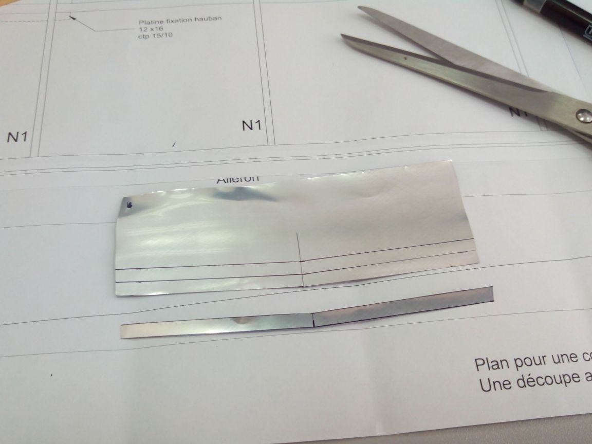
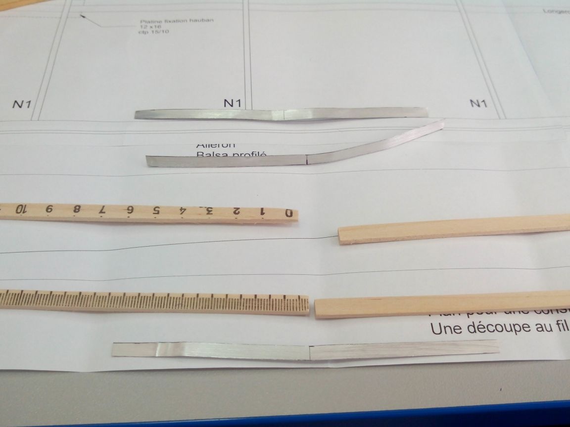
We glue two slats with PVA glue, after having clamped one corner between them.
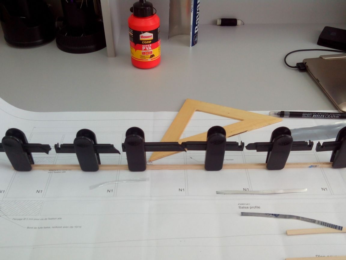
Glue two more corners outside.
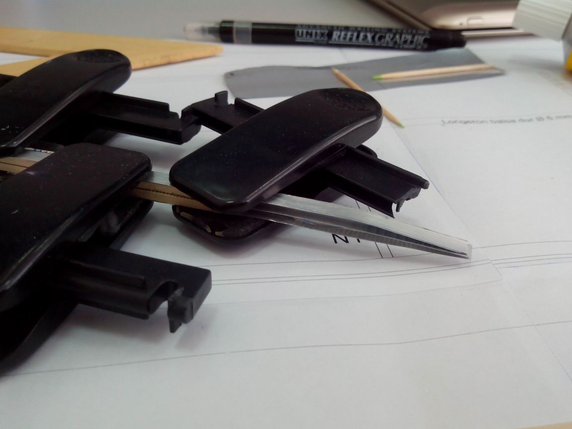
After drying the glue, glue the second half of the spar.
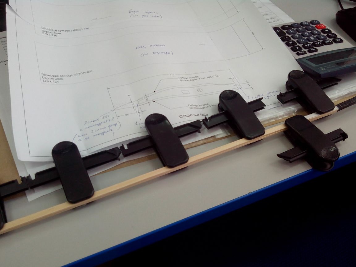
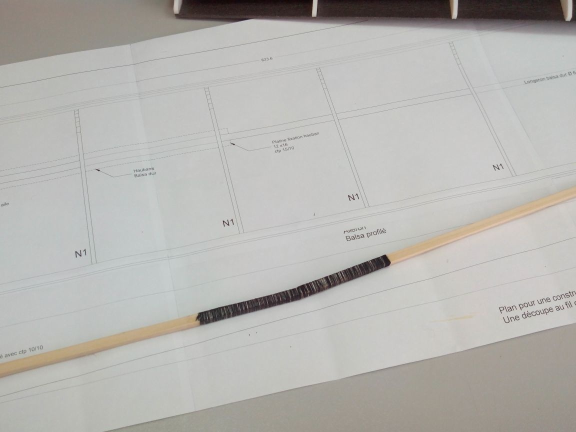
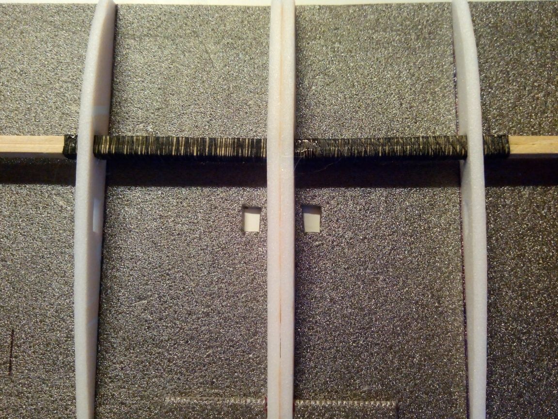
And wrap the central part with thread with glue.
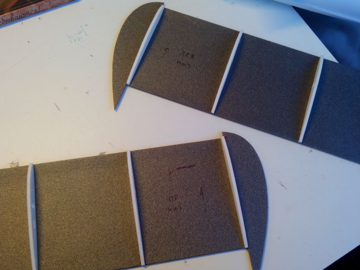
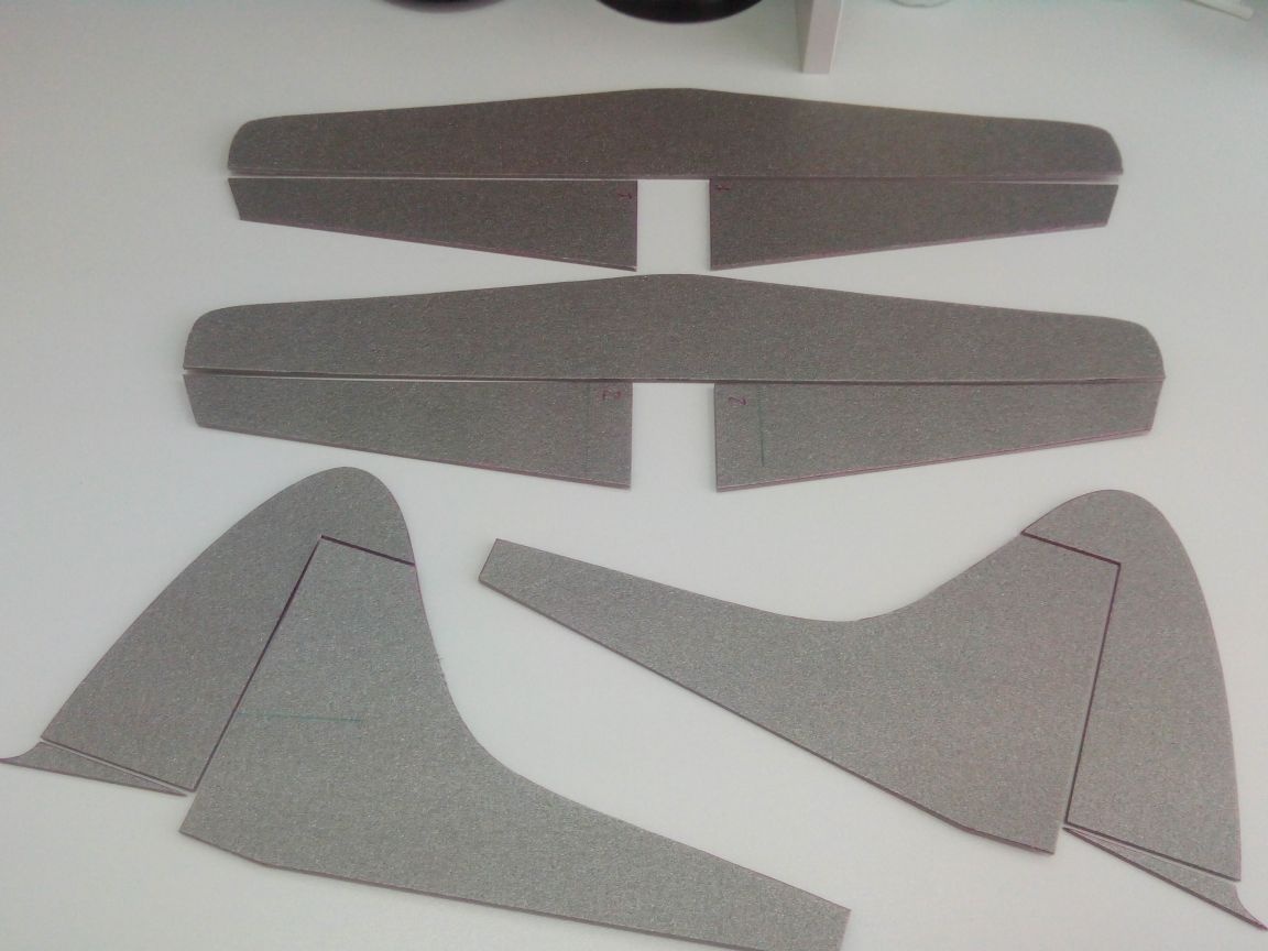
In size from the drawing, we cut out the lower part of the wing console from the depron.
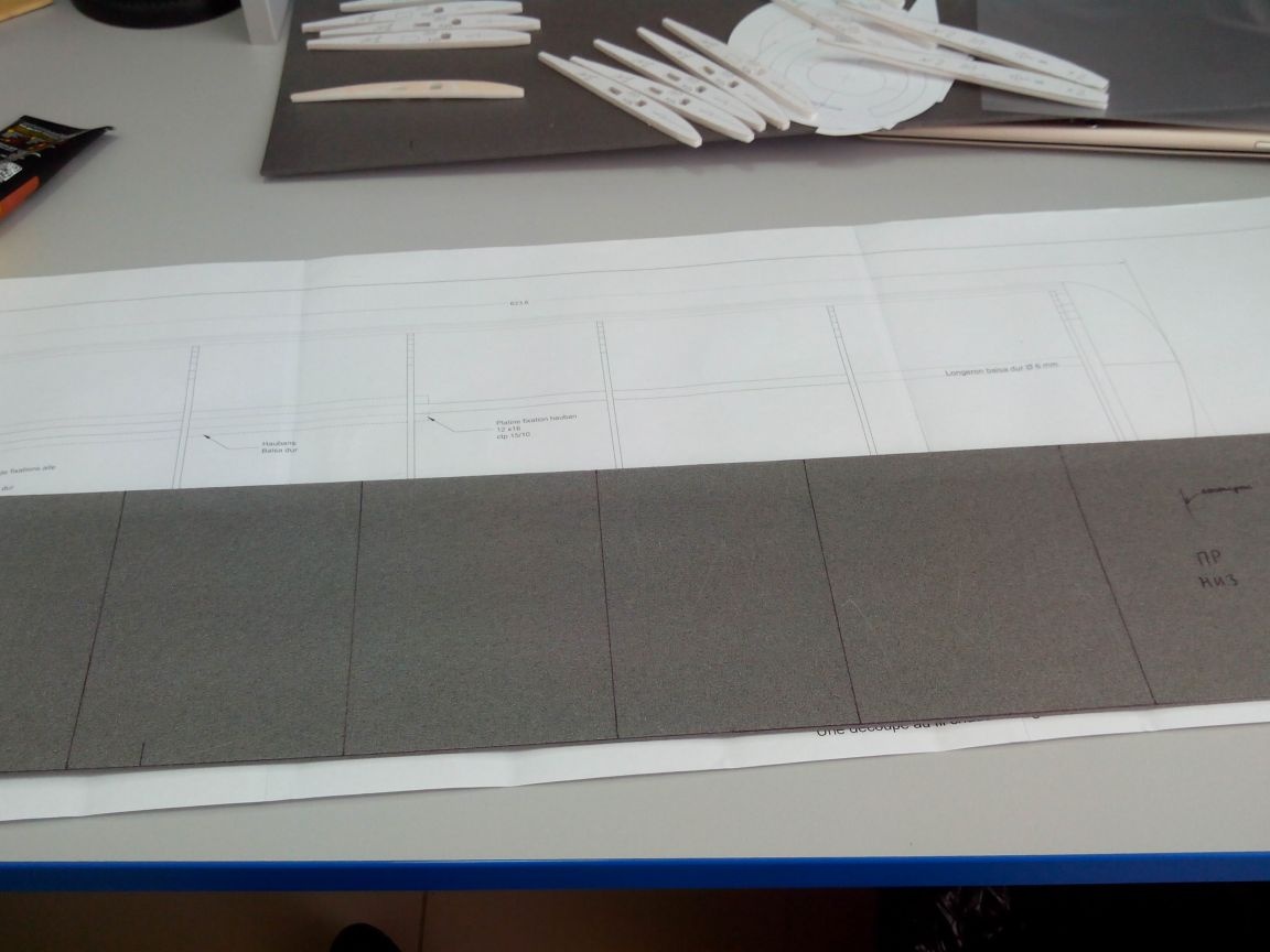
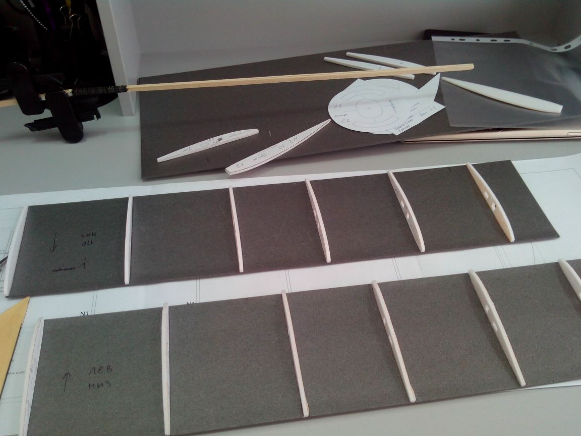
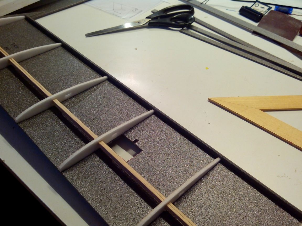
We glue ribs to it, after making holes in them under the spar and wires of the servo drives of the ailerons.
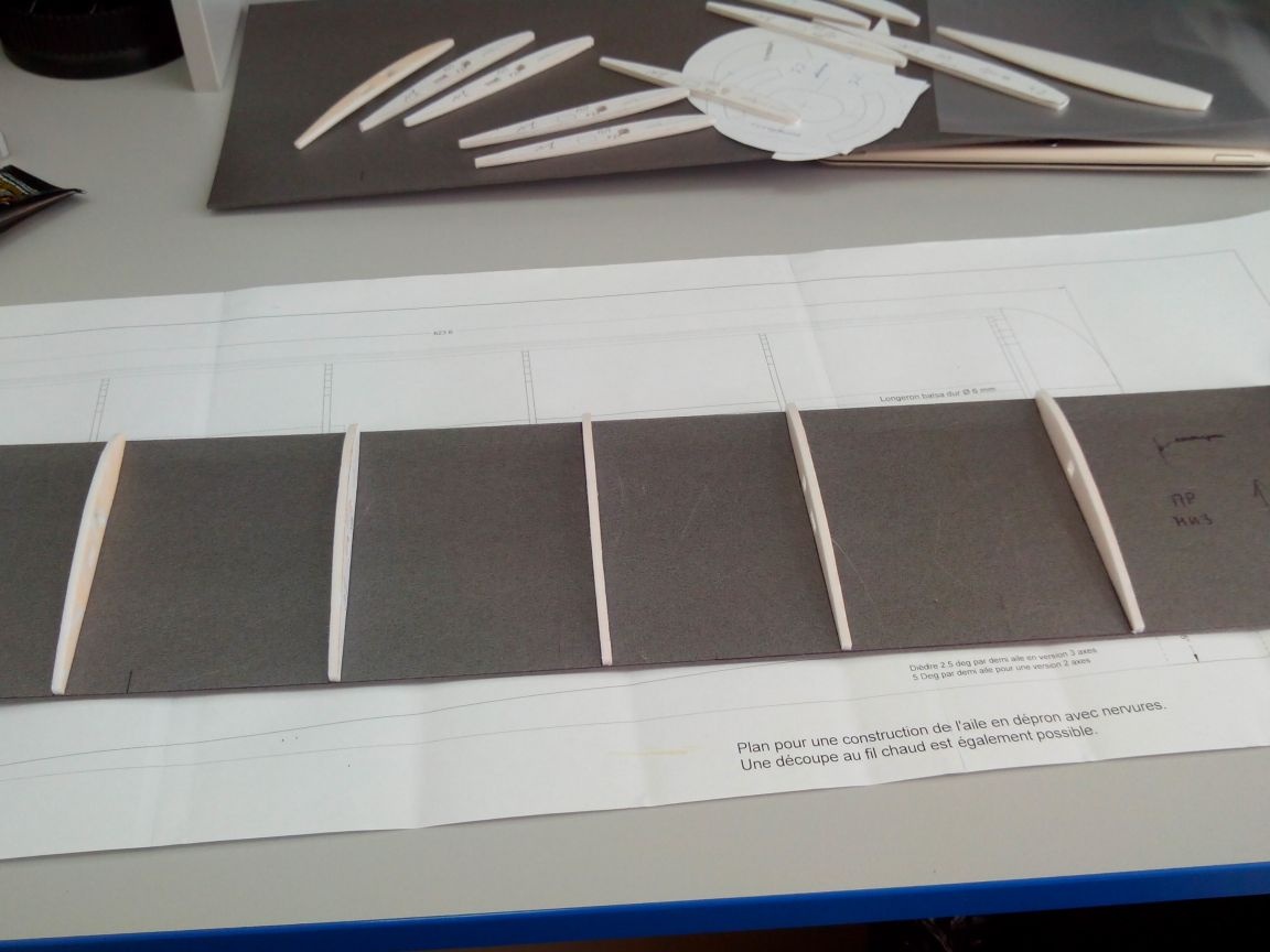
Similarly, we make the second console.
Cut the wingtip pattern.
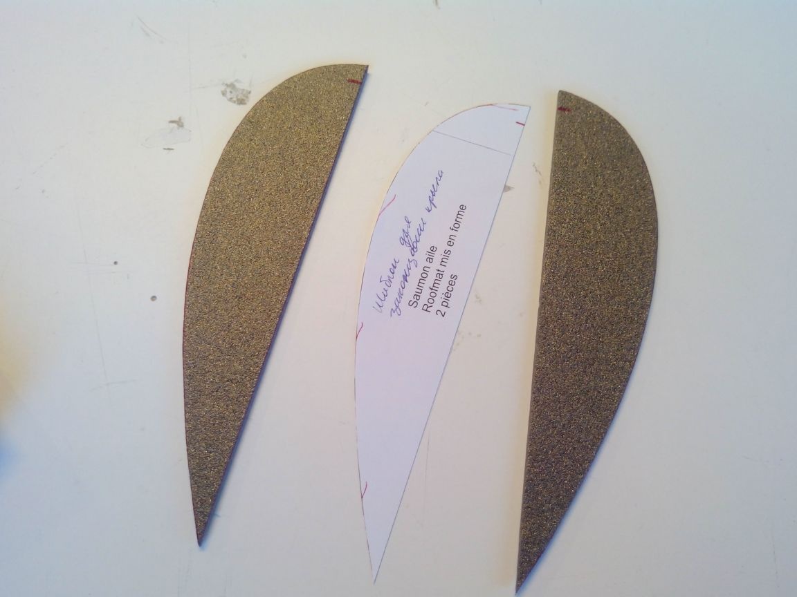
We glue the endings to the lower parts (although, if the length of the material allows, the lower part can be cut whole).
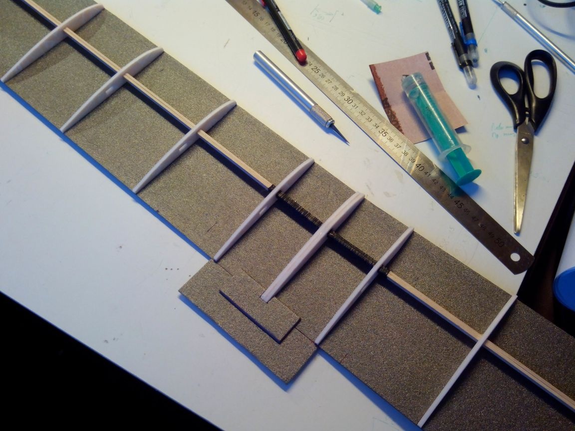
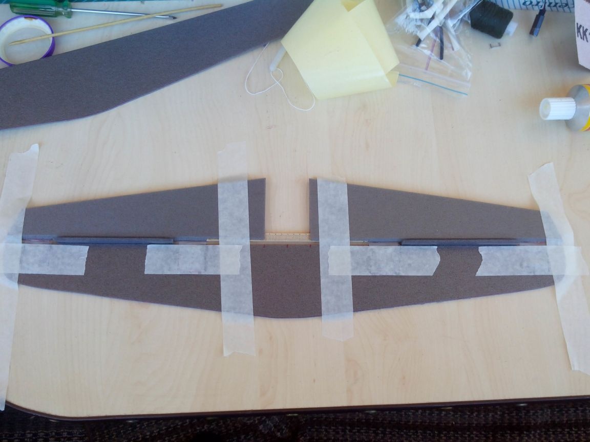
We glue the wing consoles together by inserting glue into the holes in the ribs of the spar and glue the central part to the trailing edge.
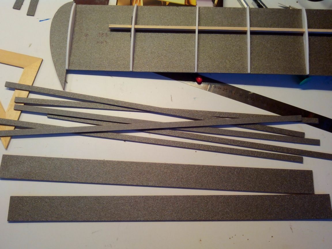
Cut the ailerons, leading and trailing edges from the depron.
In the lower part of the wing, cut holes for the aileron servos.
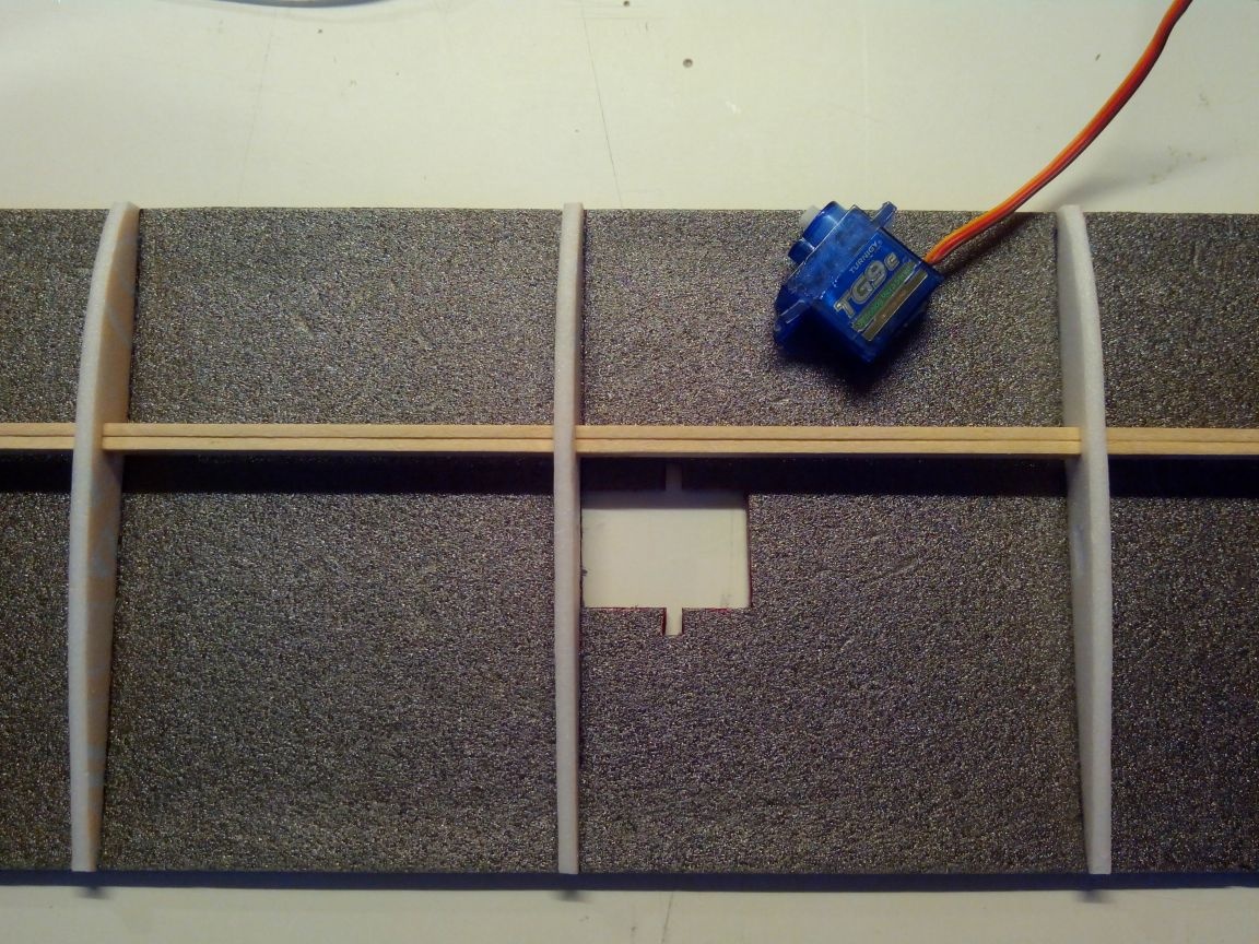
And in the central part there are small holes for wires.
Glue the trailing edge.
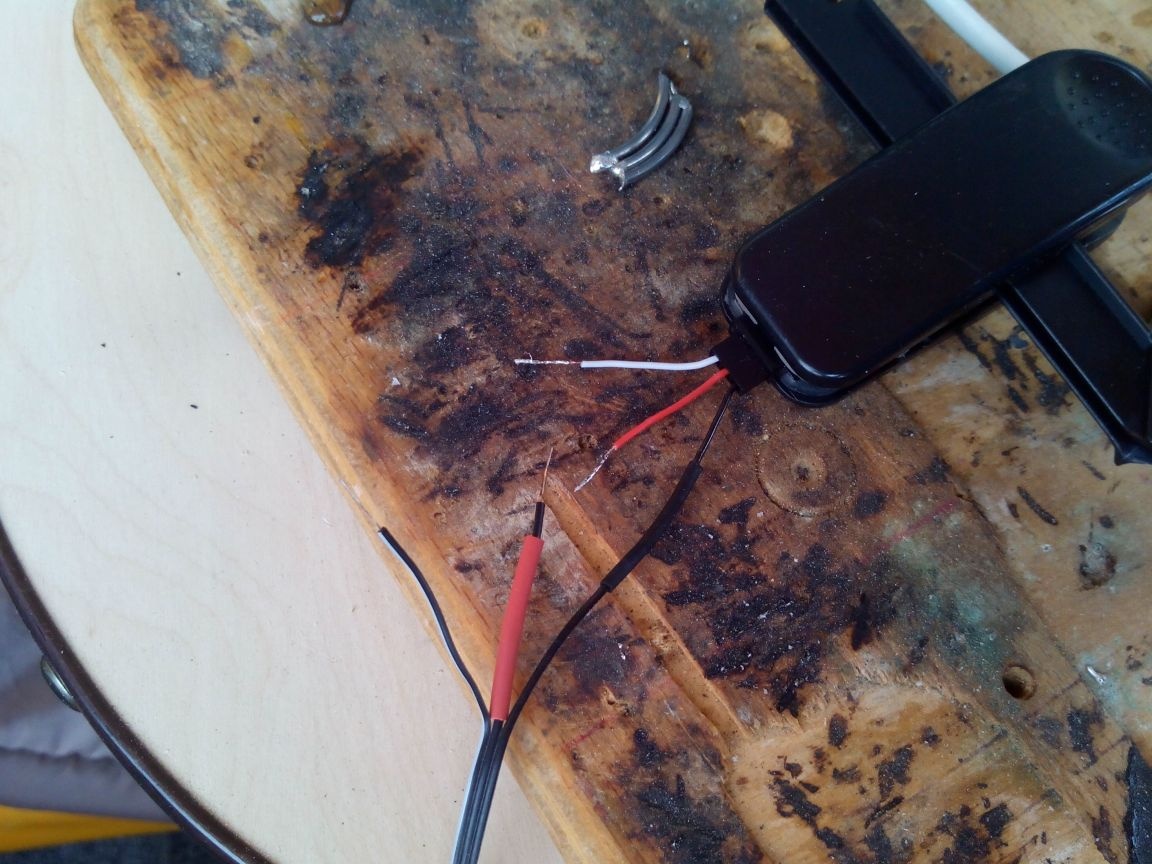
Since there were no purchased extension cords, I decided to make a long Y-cable for connecting ailerons. To do this, I took an old cable from an unnecessary floppy drive and cluttered connectors from broken servos.
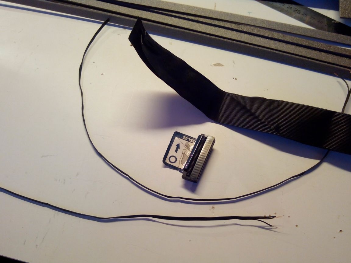
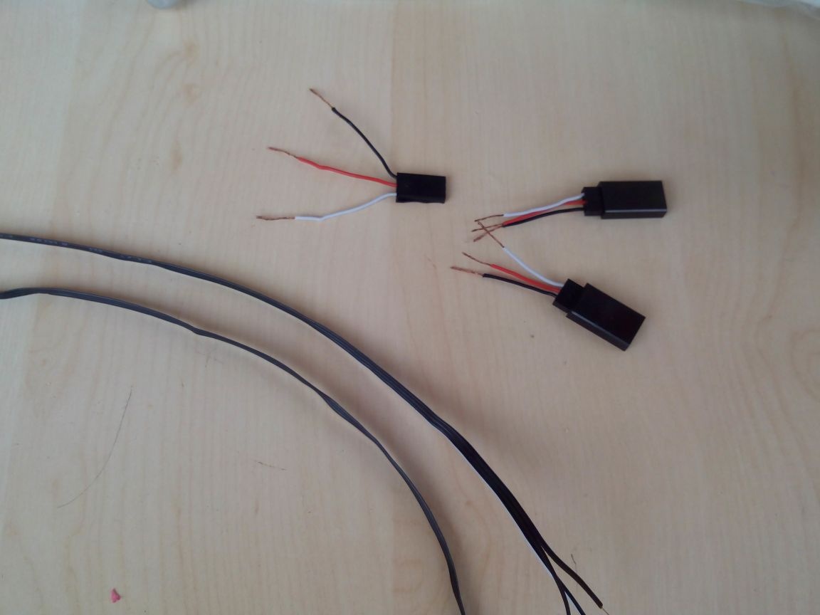
We solder the halves of the Y-cable, not forgetting to mark the necessary contacts with multi-colored heat shrink.
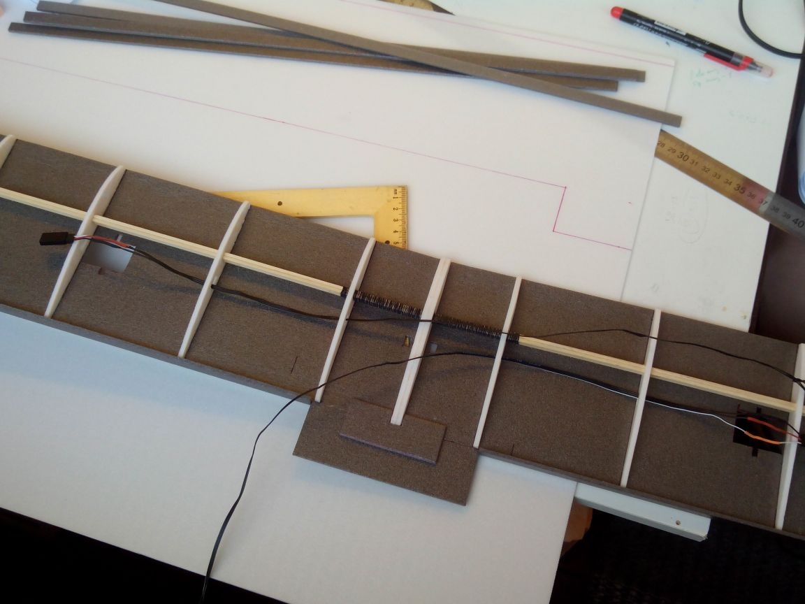
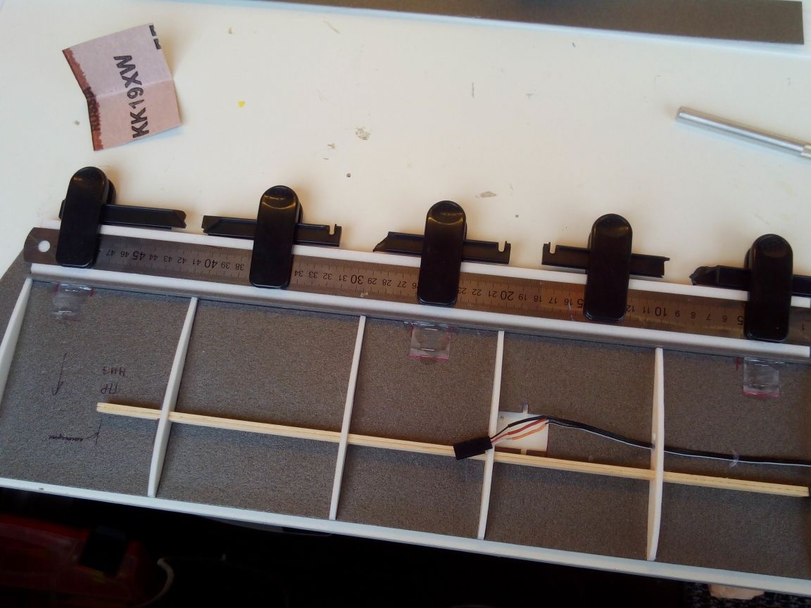
We stretch the halves of the cable in the wing and bring the ends out.
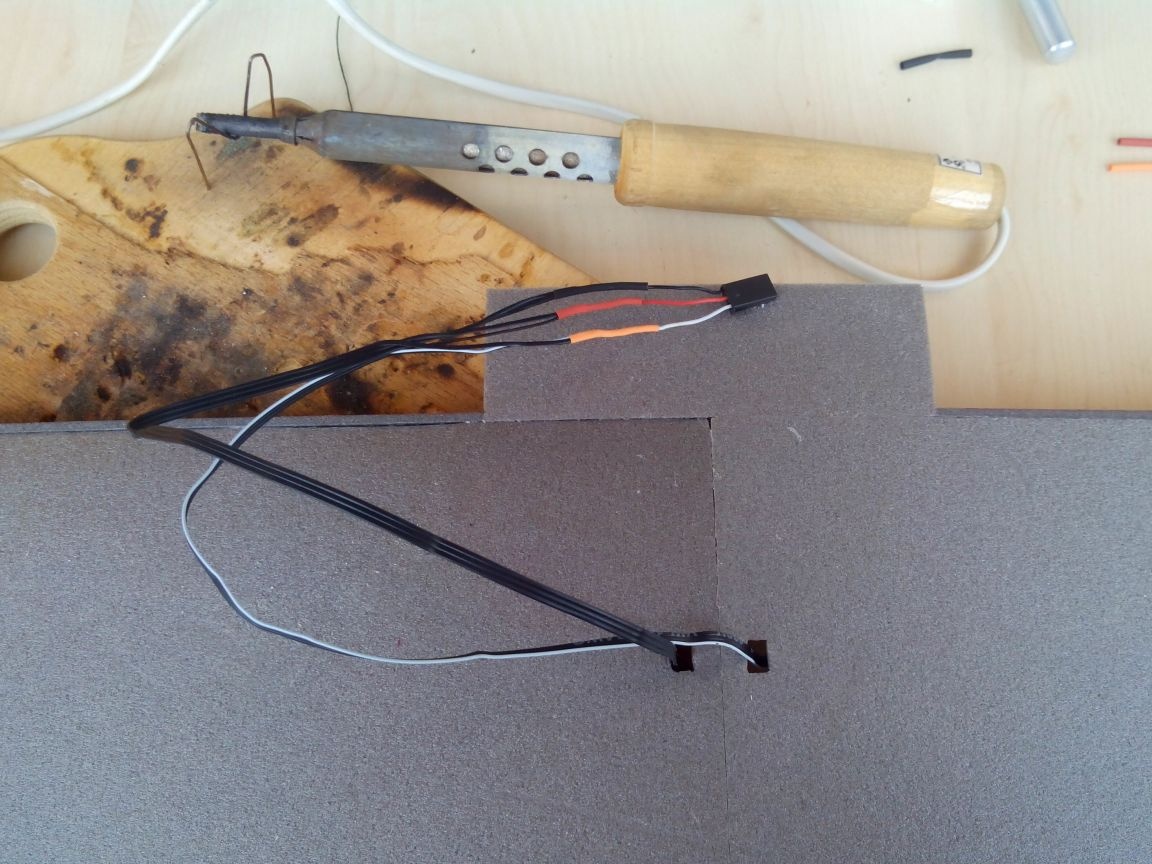
Solder the wires and solder the connector.
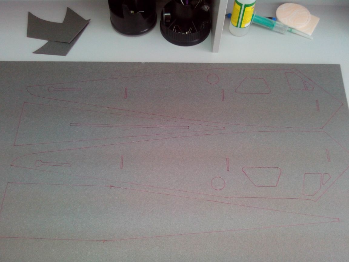
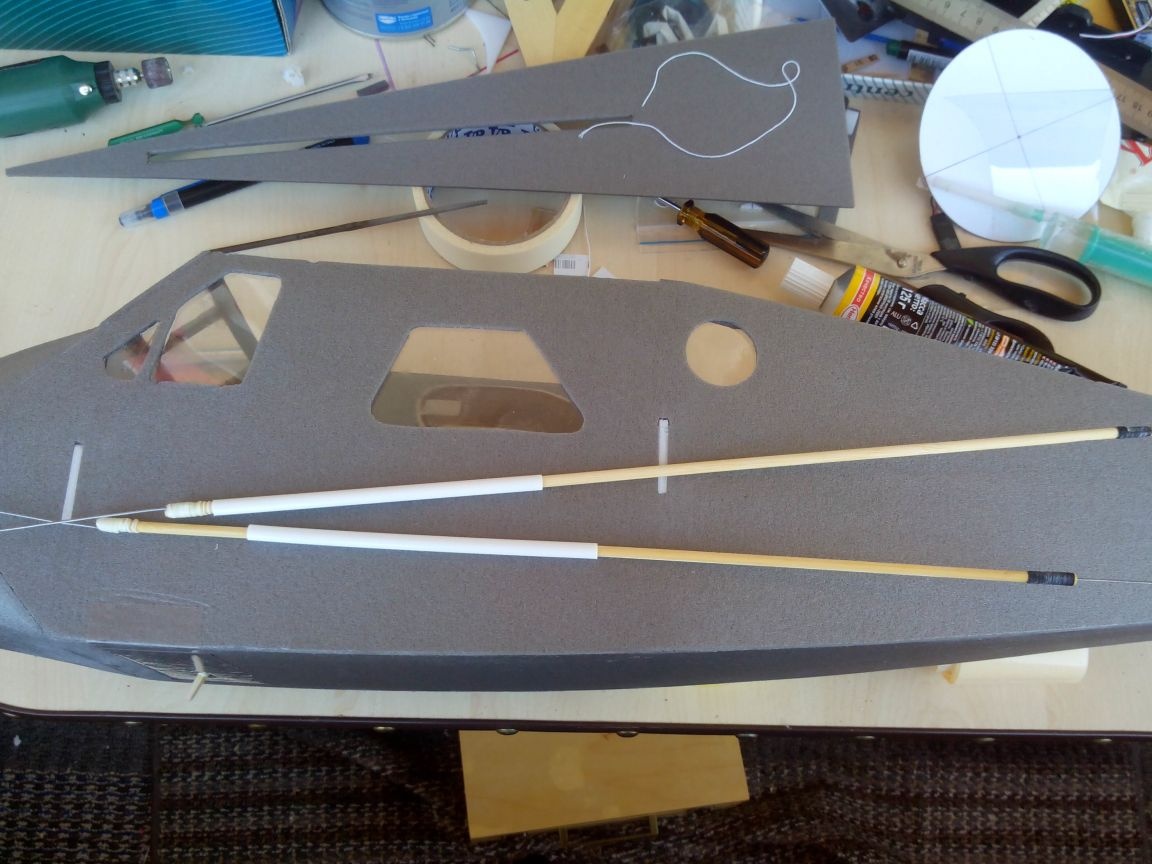
We draw the upper parts of the wing on a piece of depron (the gray deproin is over, only white was found in the store - this greatly affected the color of the model in the future).
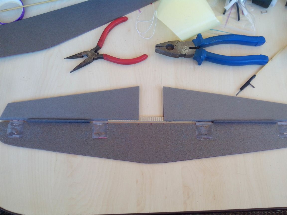
From thin plastic from the packaging with the help of a stapler we make loops and sand them.
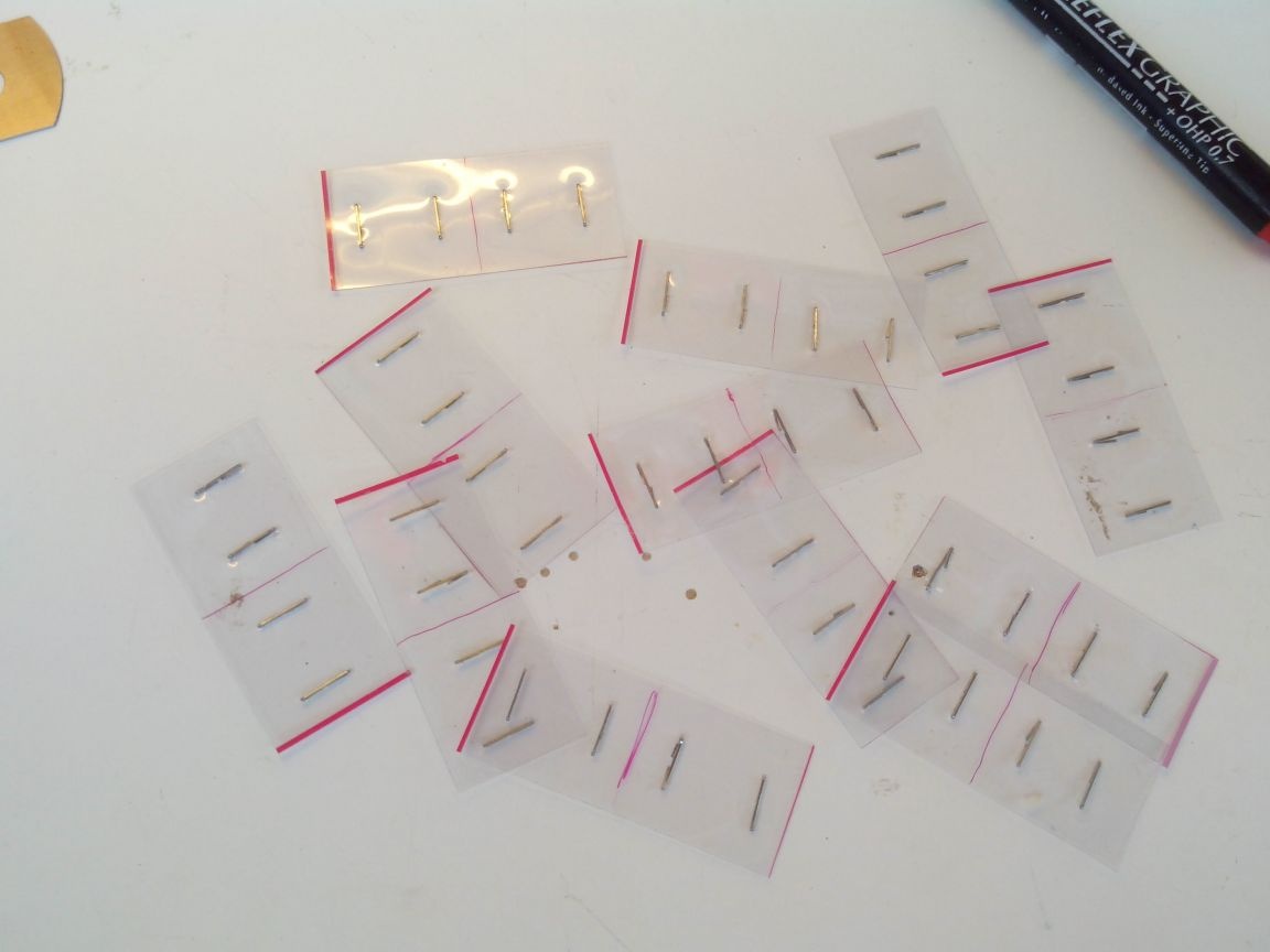
We make cuts in the trailing edge of the wing and paste loops on the epoxy (three pieces per aileron)

Glue the ailerons, holding the halves of the ailerons in the loop.
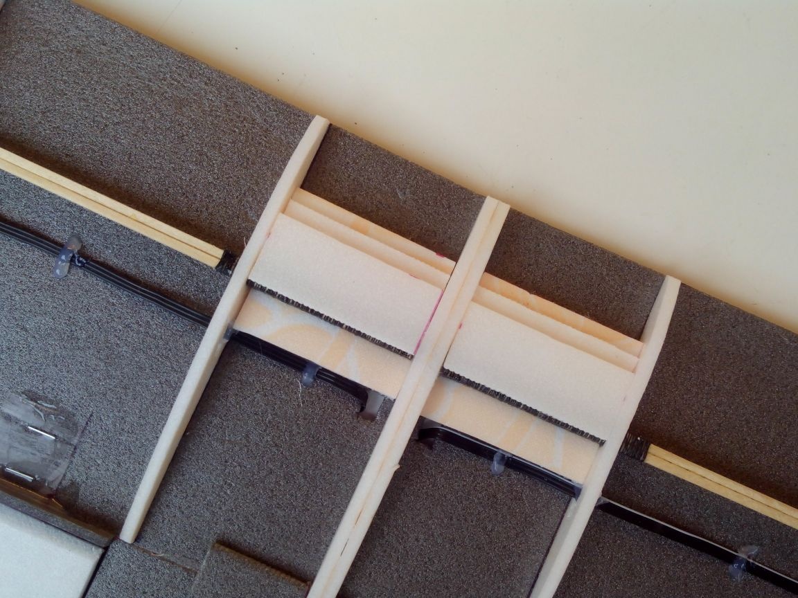
We reinforce the central part of the wing with strips of ceiling - in this place there will be bolts for attaching the wing to the fuselage.
Now you can glue the top of the wing.
After the glue has completely dried, we glue together the top and bottom of the wingtips and fix it with tape.
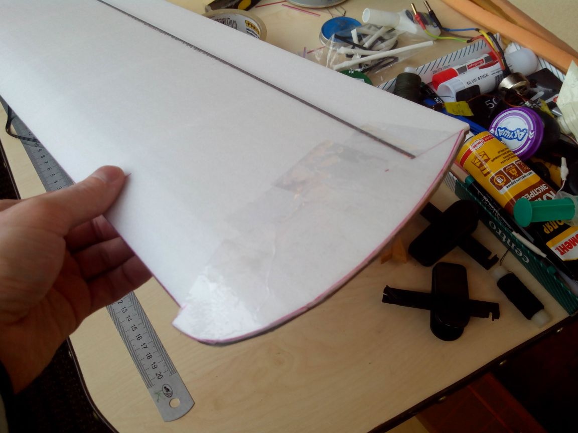
Glue one layer of the leading edge.
When it dries, glue the second layer of the leading edge.
After a couple of hours, the wing can be sanded.
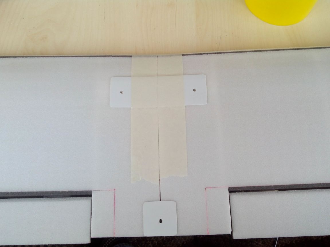
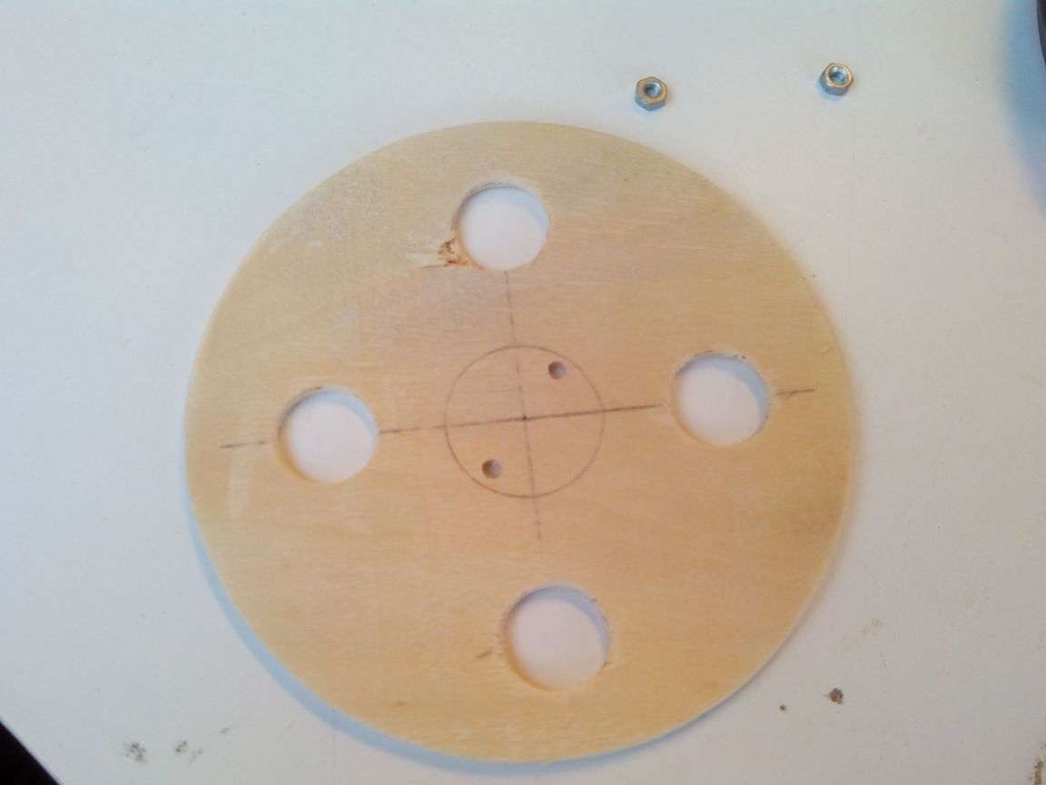
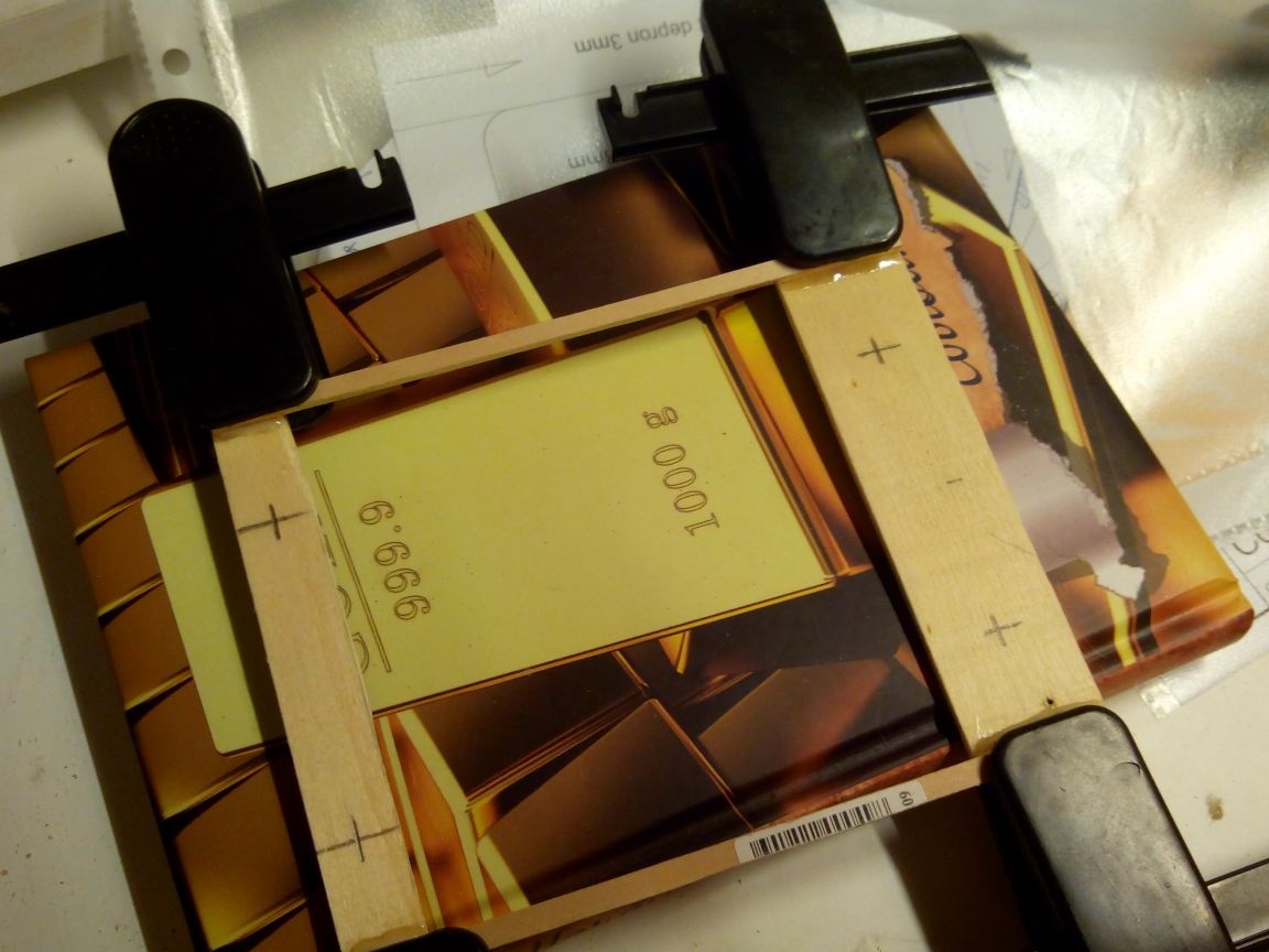
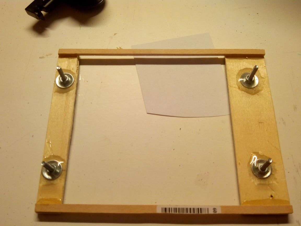
The wing will be mounted on two plywood platforms glued to the fuselage. We cut them out, and, making holes, glue nuts to them on the epoxy.
To the central part of the wing from the bottom we glue additional overlays from the ceiling tiles.
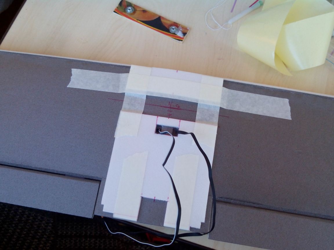
And on top we glue the pieces of plastic cards - so that the mounting bolts do not fall into the depress.
Tape the wing with adhesive tape in the desired colors.
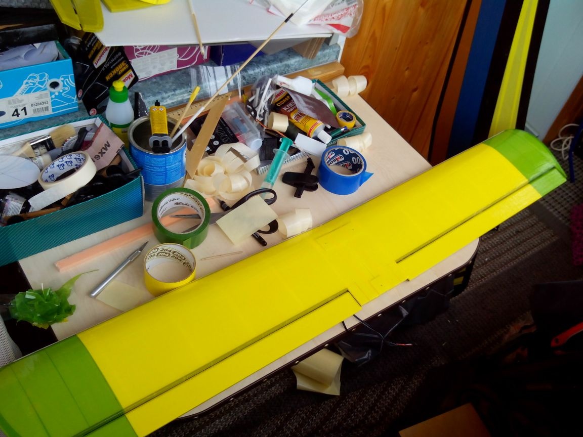
The bottom of the wing contrasted for readability of the model in the air.
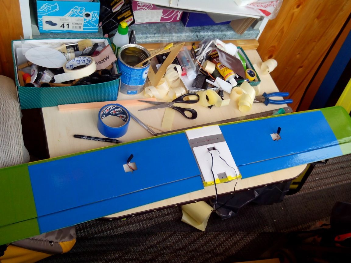
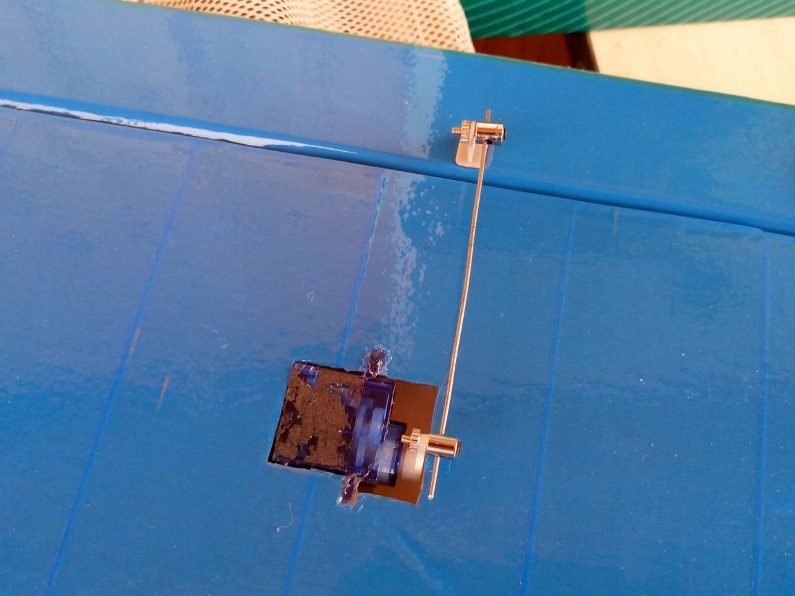
We glue the aileron servos, steel wire traction, fasten with clamps.
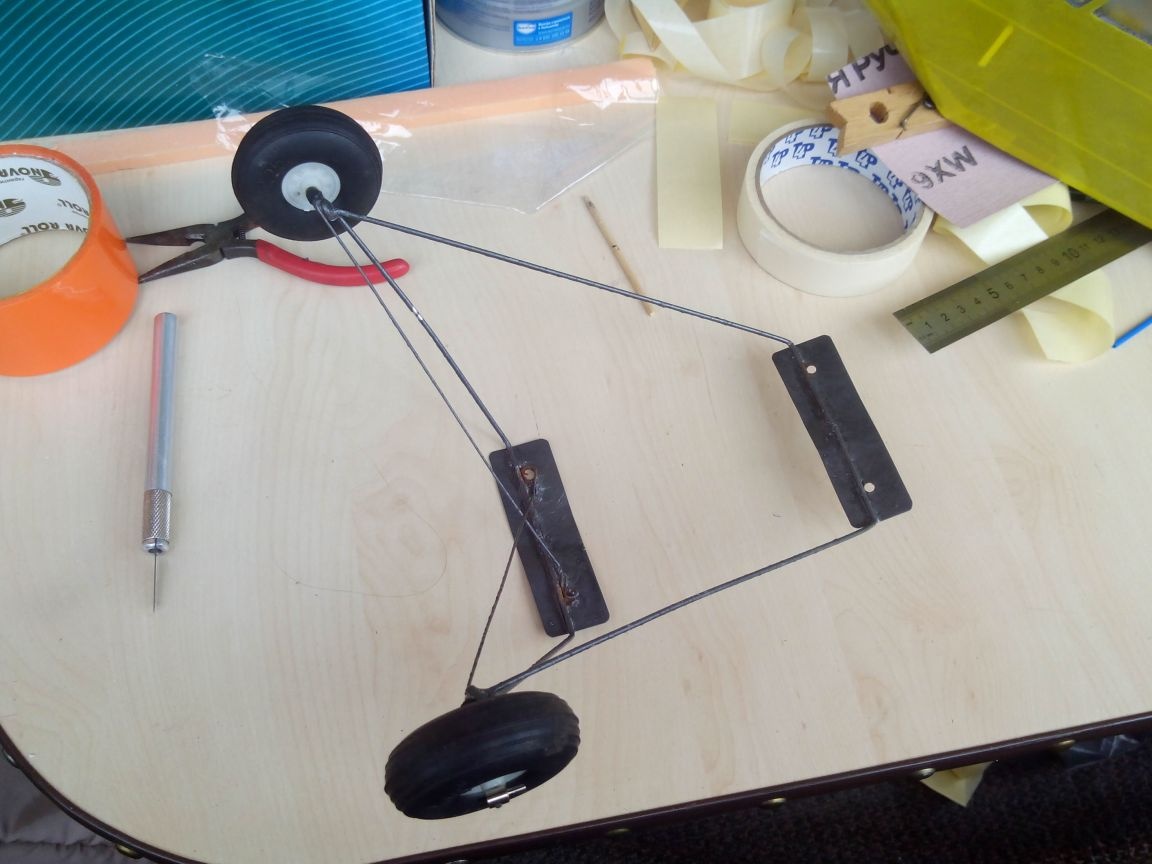
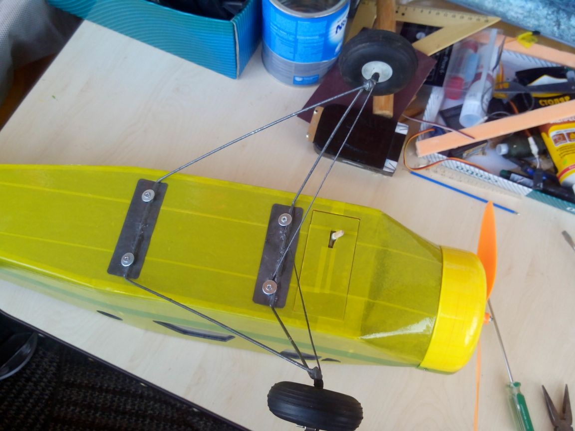
Step 3. Chassis
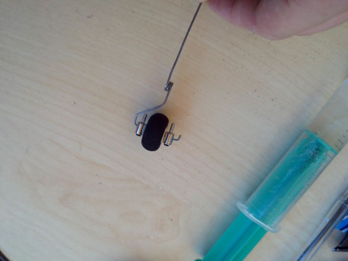
A tail chassis wheel is purchased, with a diameter of 2 cm. We bend the rack from steel wire, making a spring at the base (a couple of turns is enough) to absorb during landing. We fix the wheel with tie rods.
For reliable fastening in the fuselage, we make a plywood platform.

The front landing gear is welded from bicycle spokes and tin strips, which I talked about in the article about the manufacture of landing gears.
The wheels are also purchased, with a diameter of about 6 cm. Attached to the axle with tie rods as well.
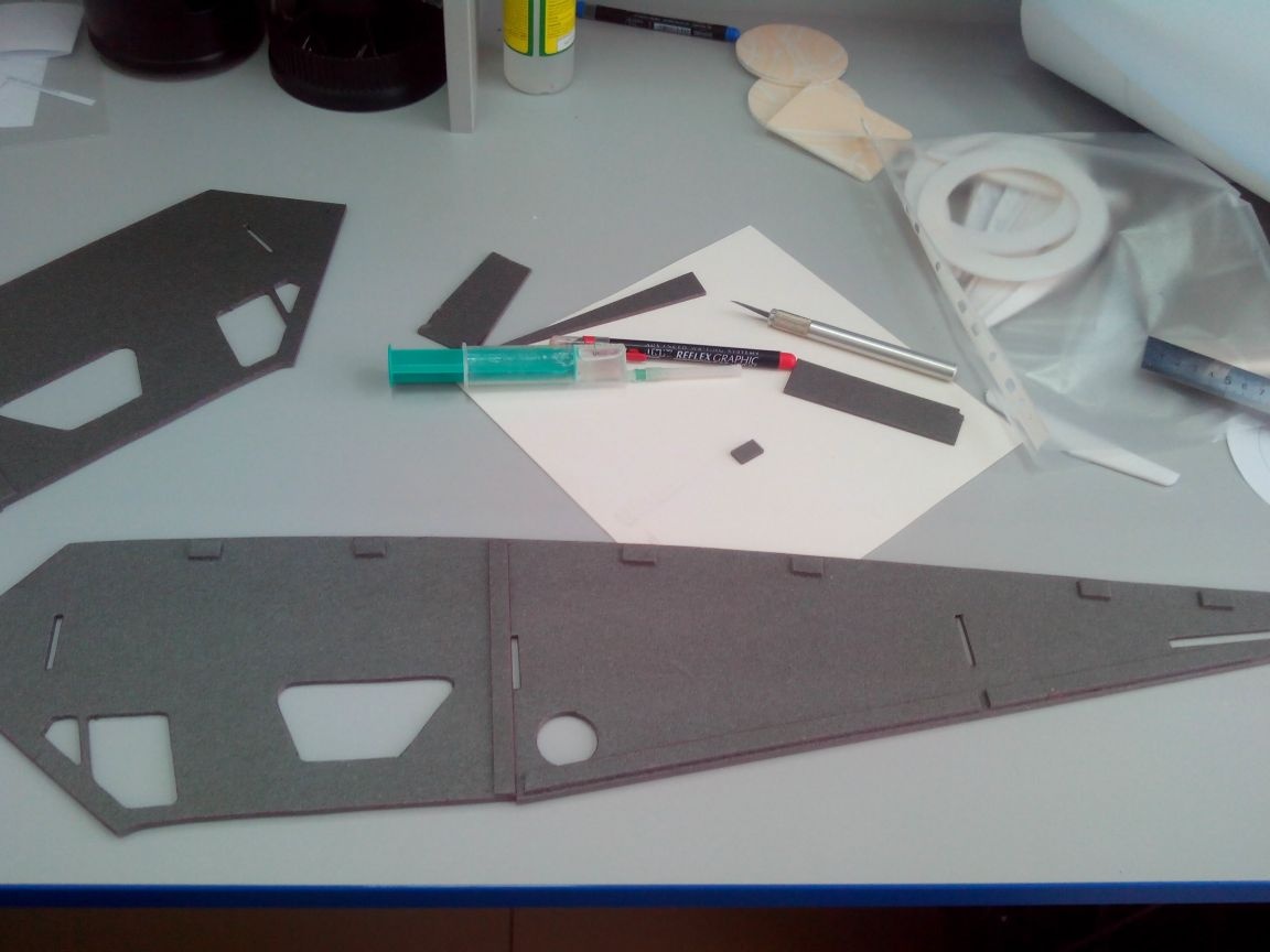
Step 4. The fuselage
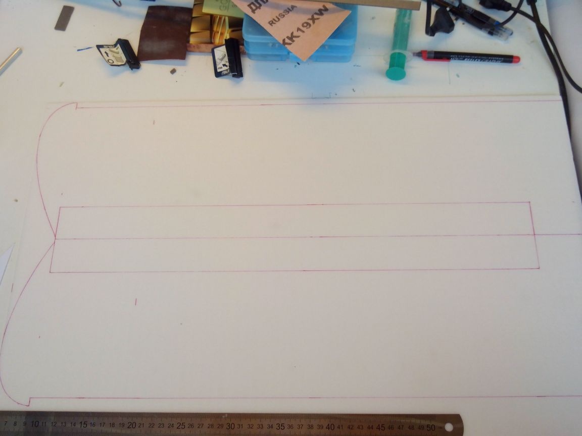
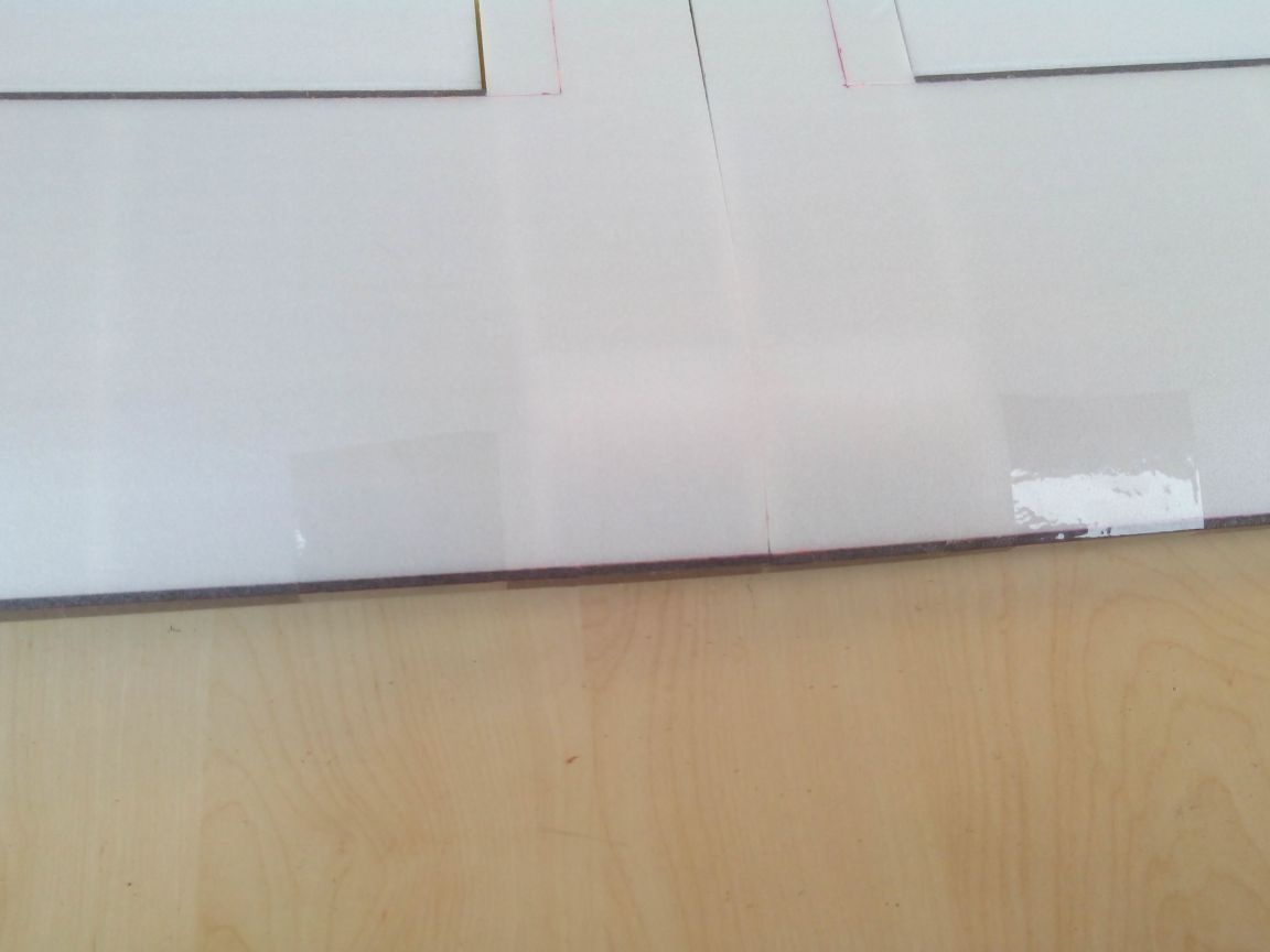
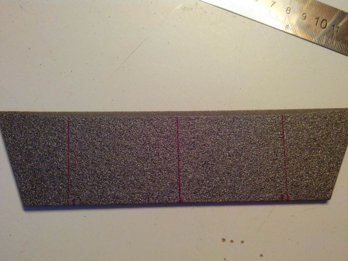
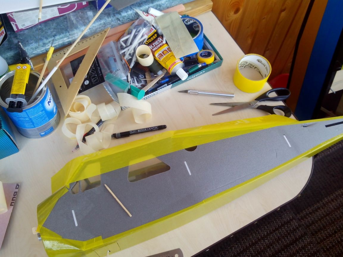
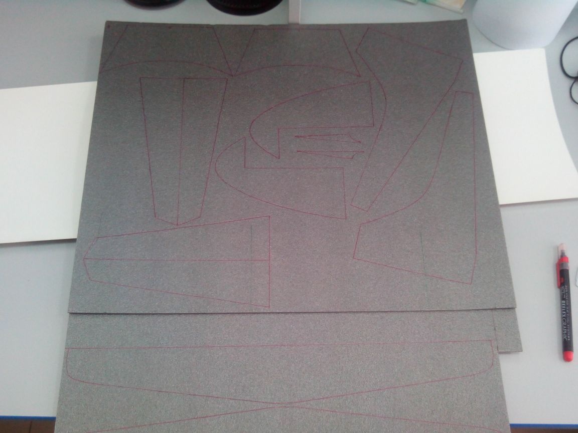
Cut the frames from the ceiling.
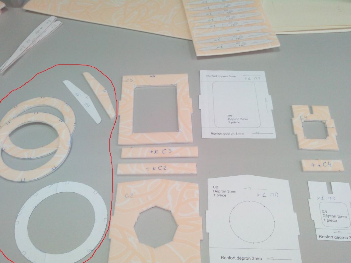
He circled in red those parts that I did not need, since I modified this part a little.
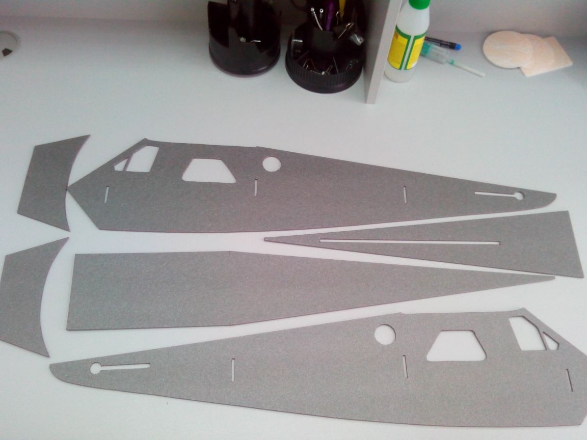
We mark it on the platform and cut out the details of the fuselage.
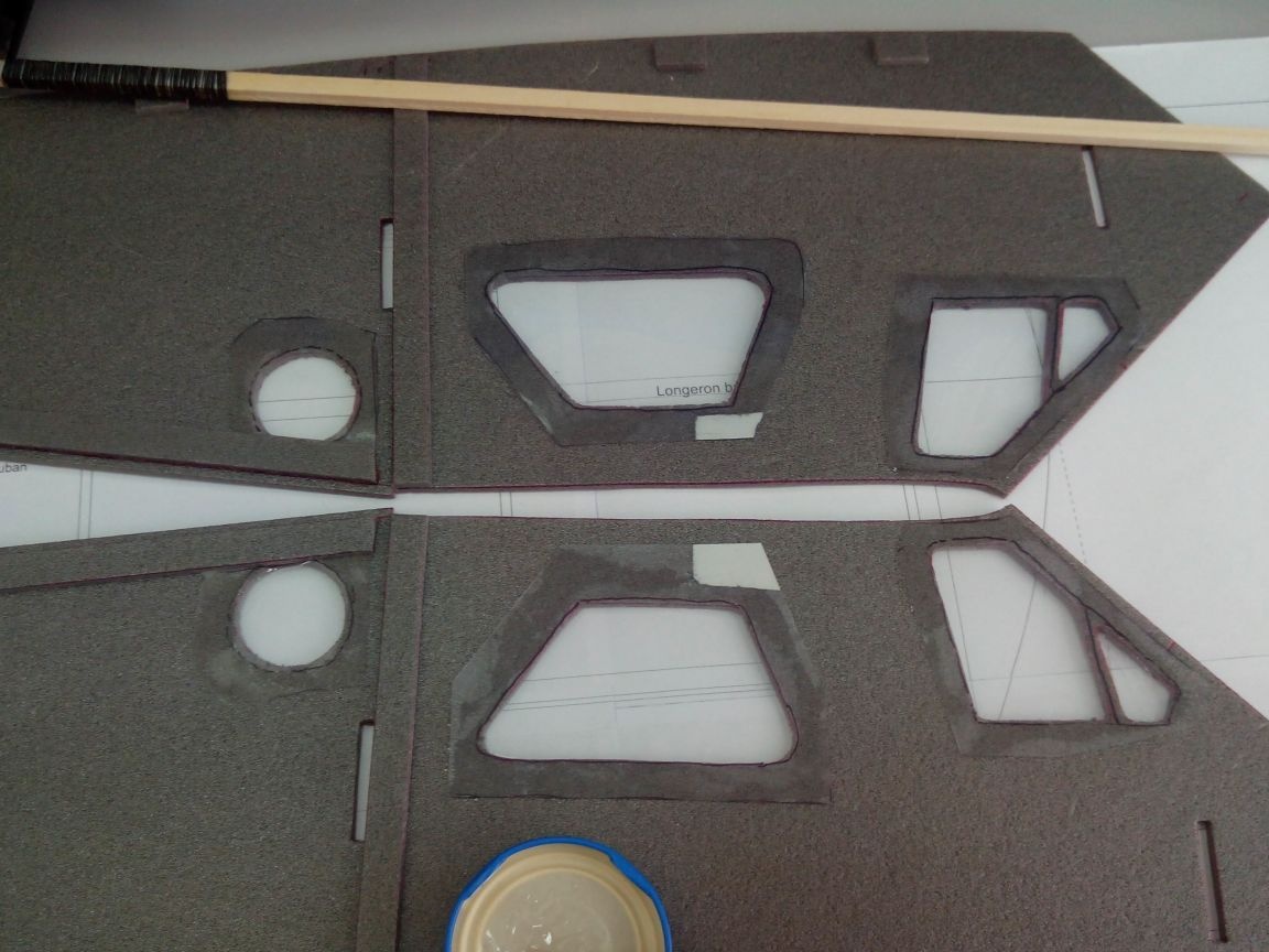
To simplify gluing the upper and lower parts, we glue small pieces of depron along the sides.
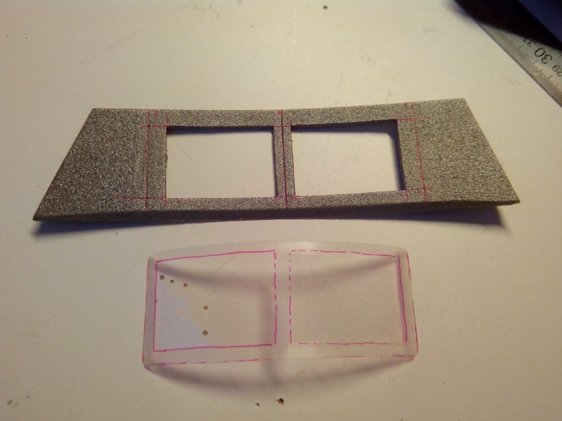
From thin transparent plastic we cut out the "glass" of the cockpit, apply it to the halves of the fuselage and draw a marker around the windows.
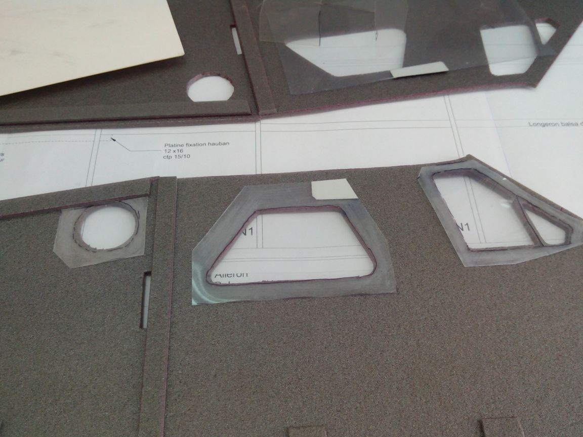
Then we skin the protruding parts and glue them with epoxy.
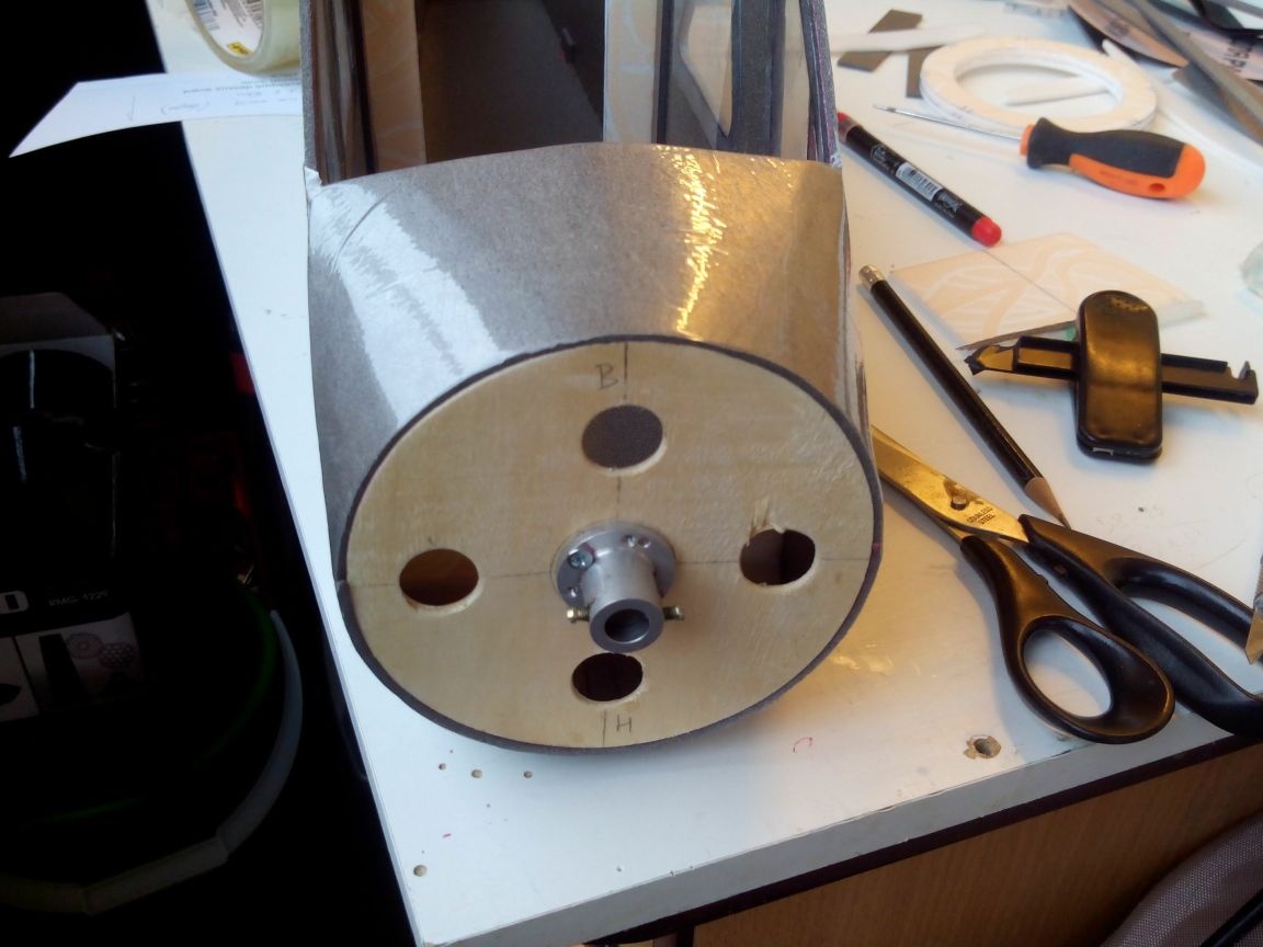
We cut engine mounts out of thin plywood.
And we fasten the engine base to it with bolts and nuts.
On the reverse side, fill the nuts with epoxy.
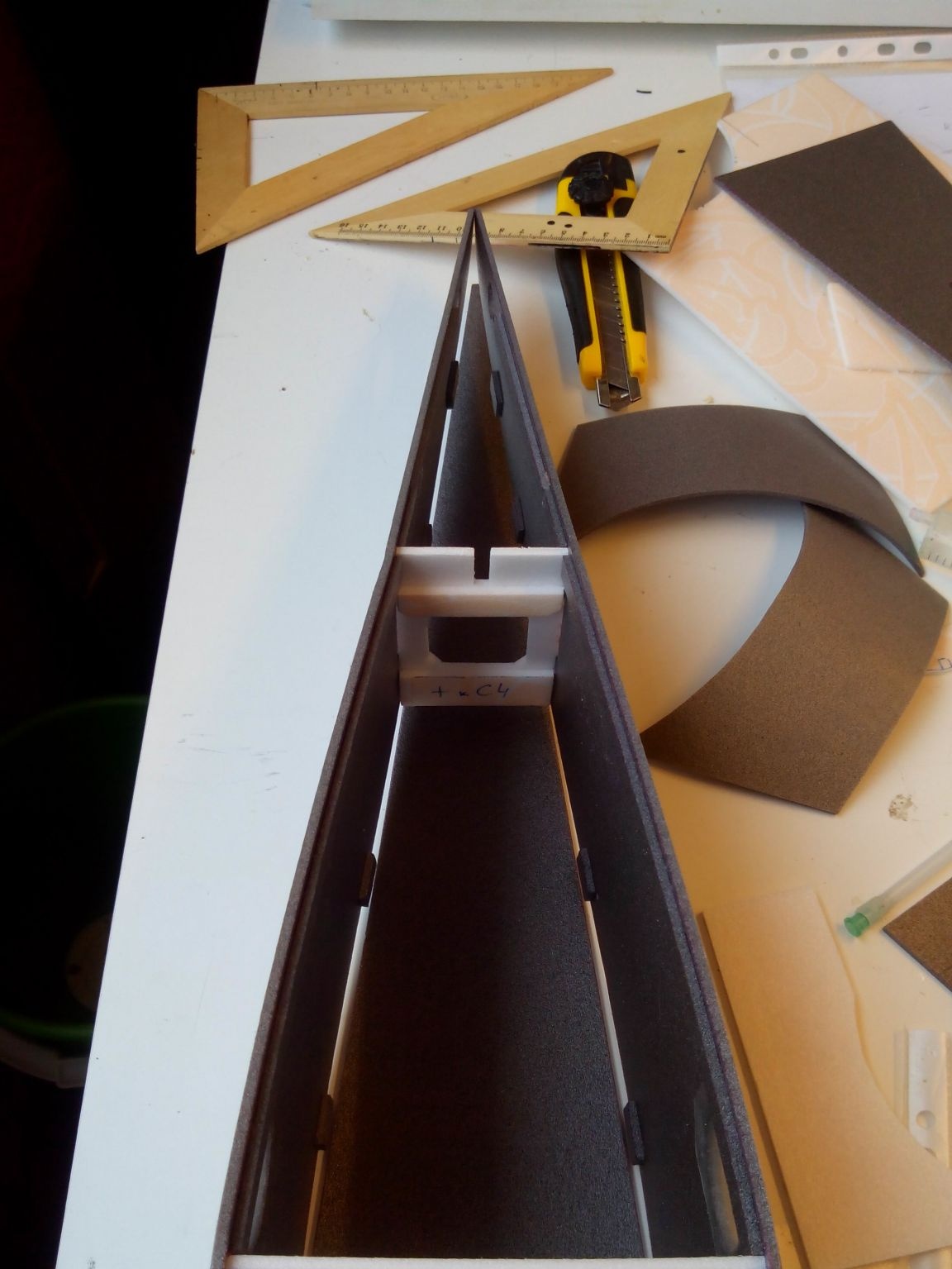
We glue in front of the sidewall and bottom of the fuselage by gluing two frames.
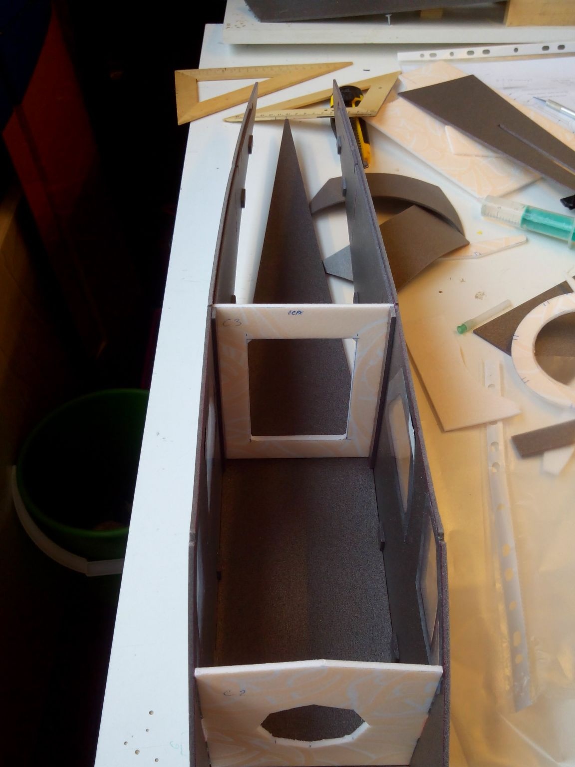
Glue the tail frame and glue the sidewalls to the tail.
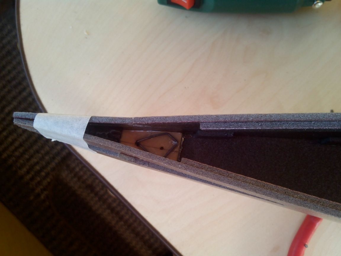
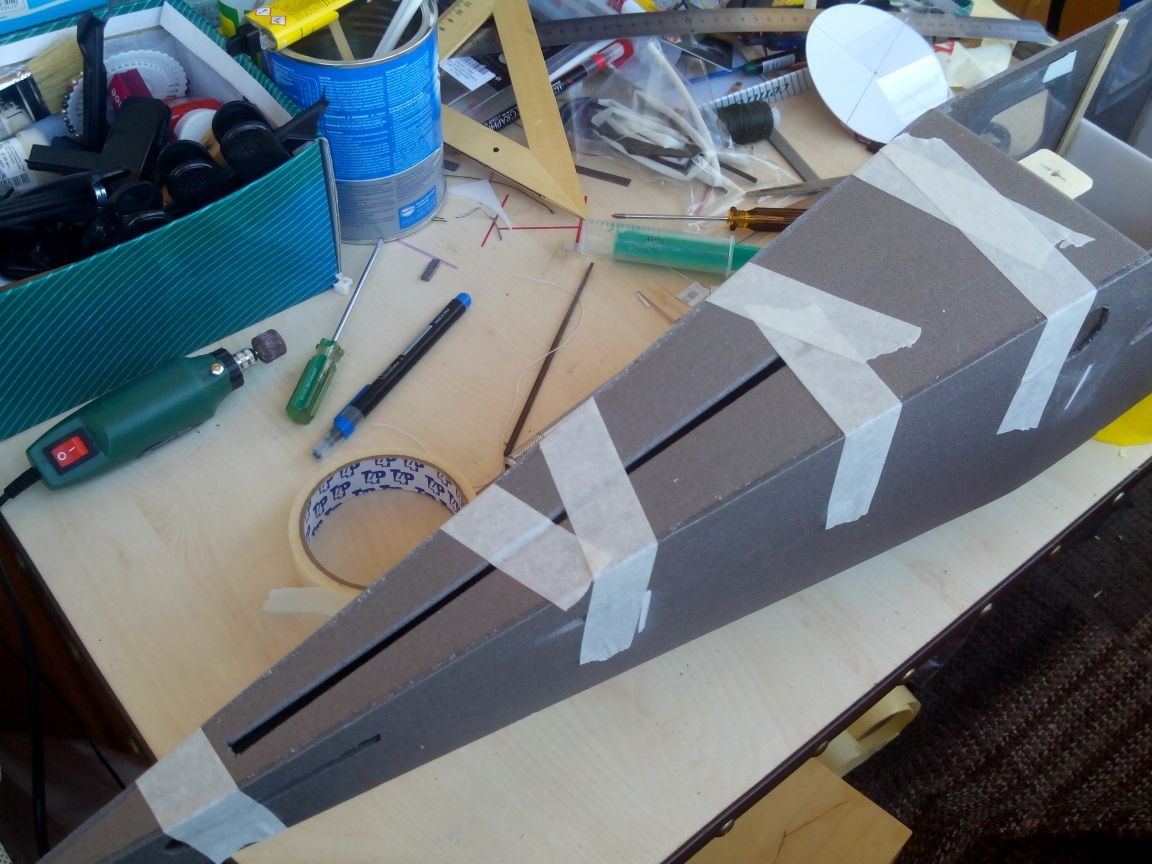
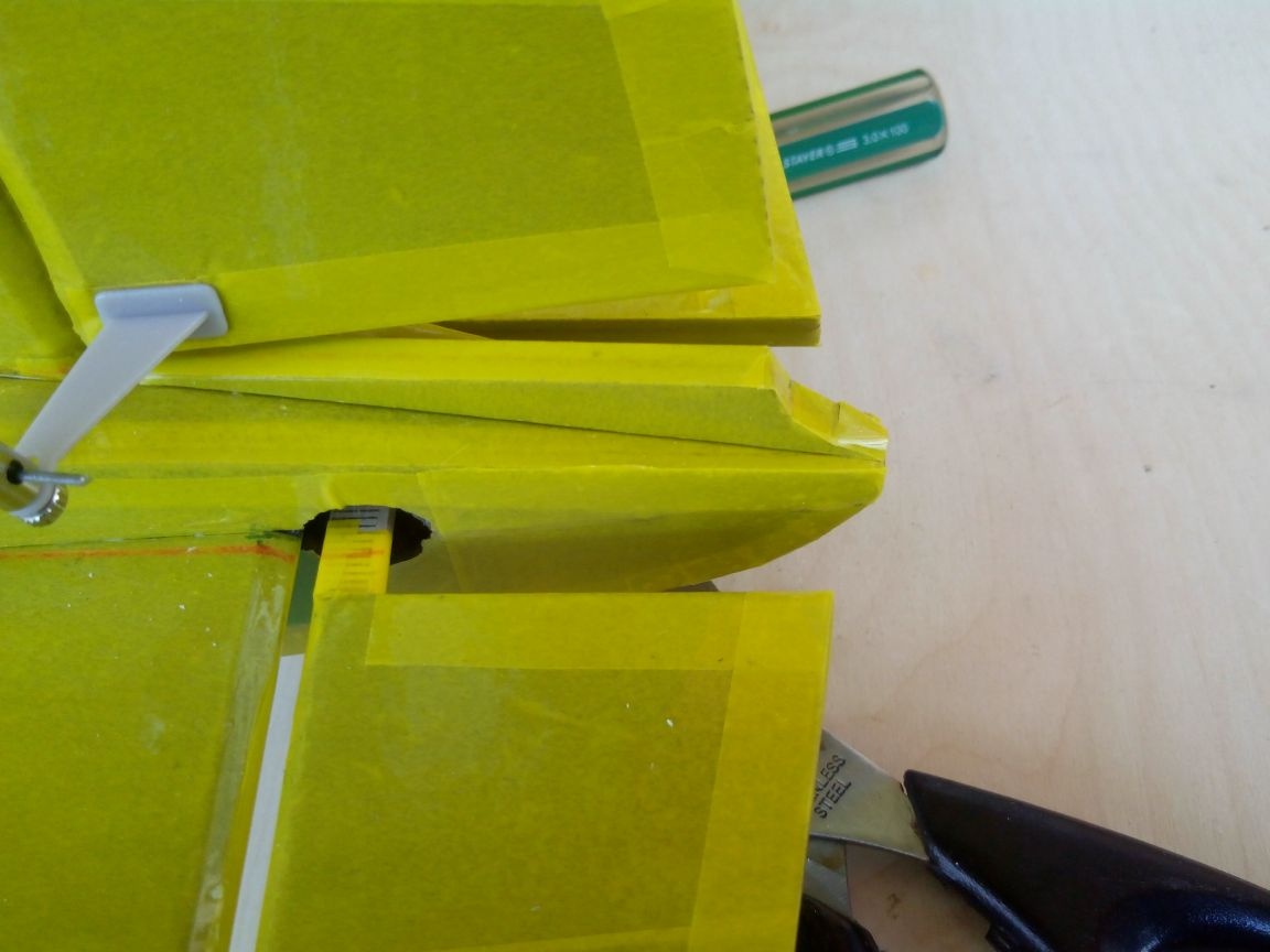
Before gluing and bending the details of the bow, I strongly recommend pasting them with adhesive tape on the outside, otherwise they will have to be cut again due to broken parts.
Glue the lower part of the nose step by step.
And fix it with tape.
Similarly, we glue the upper part of the nose, and after the glue has completely dried, we glue the motor mount (from the inside moving it outward, to the very edge).
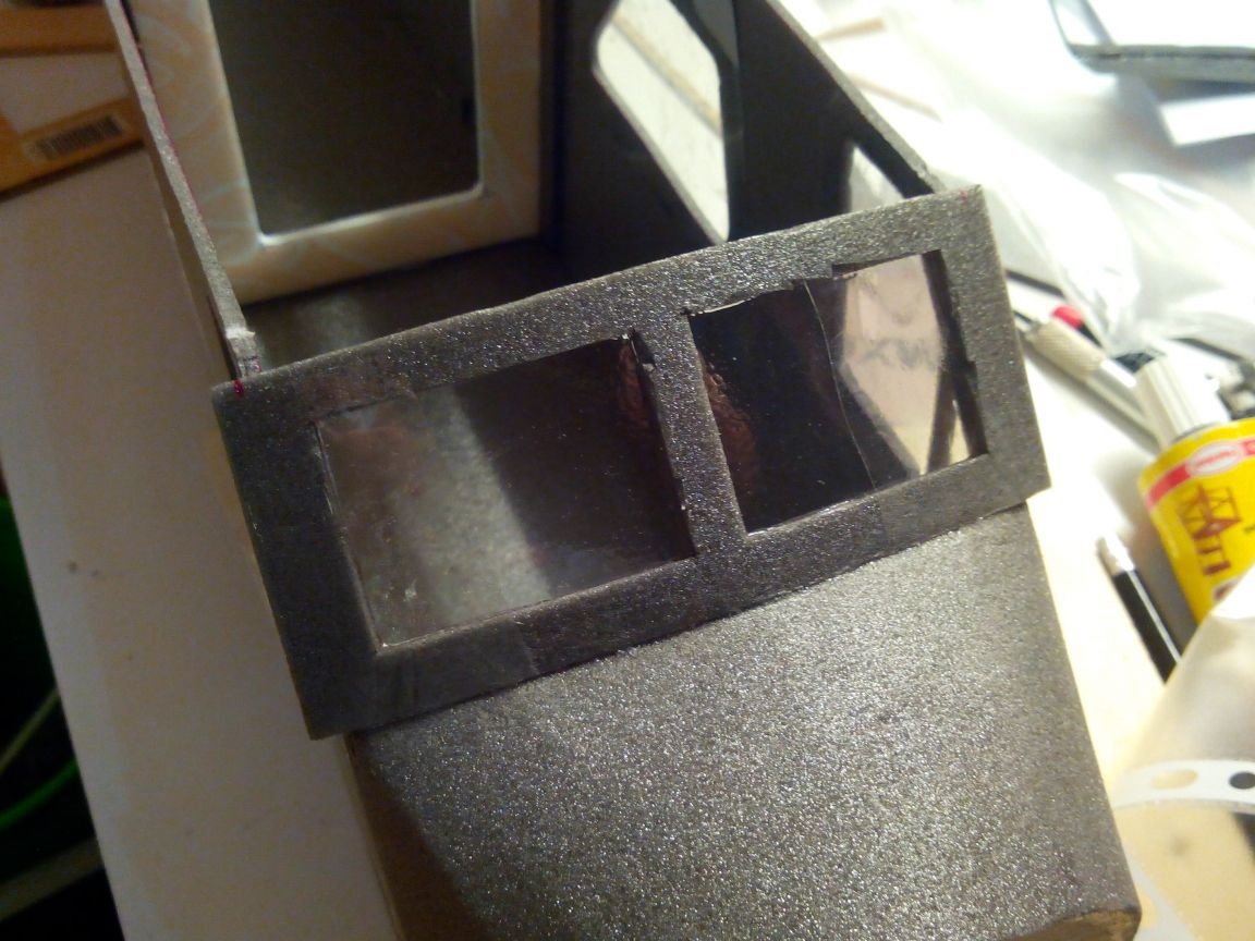
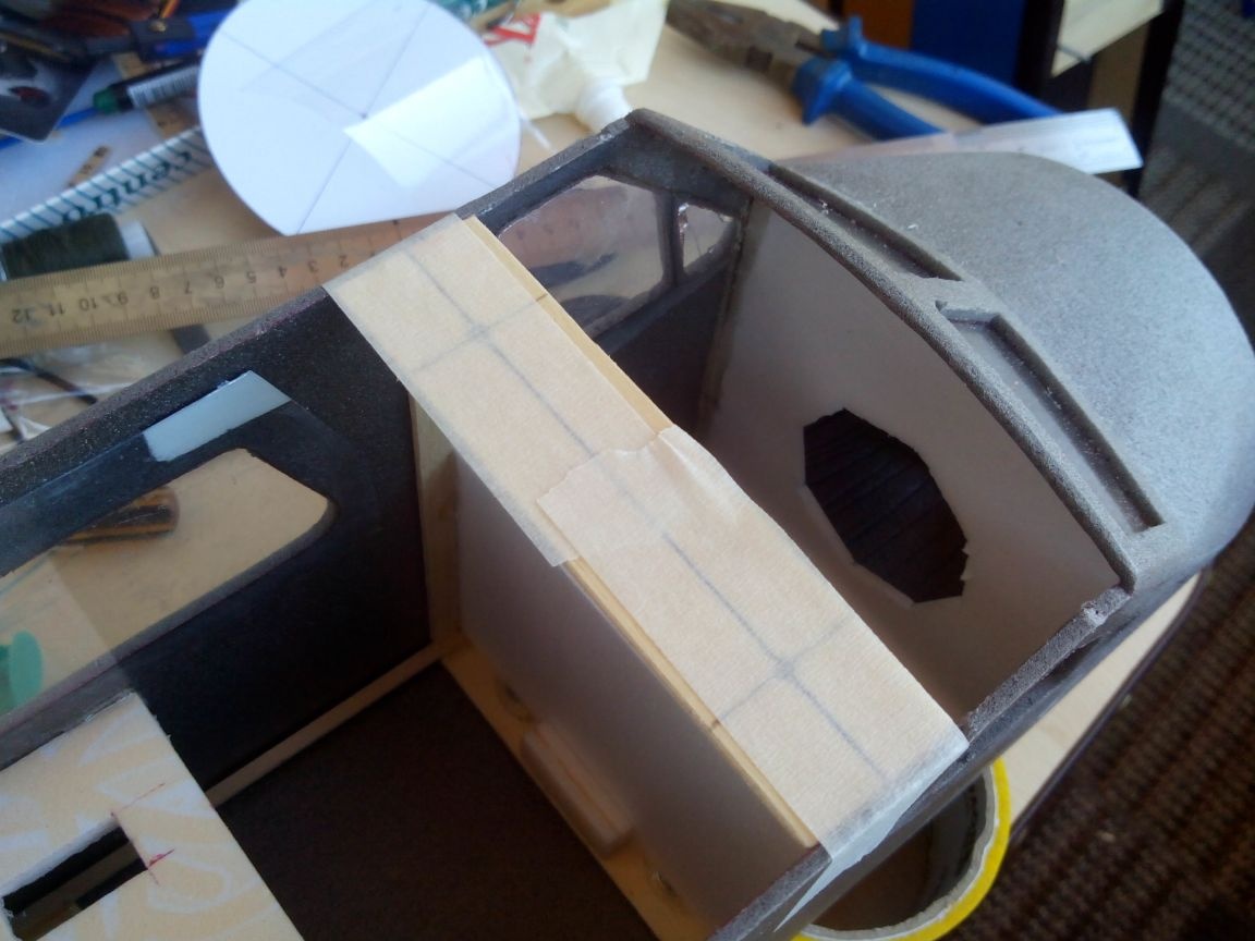
Cut the blank windshield.
We make a window in the blank and cut the “glass” to size from transparent plastic.
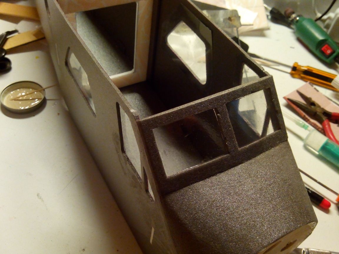
We glue the windshield similarly to the side - on the epoxy, and glue to the fuselage.
After the glue dries, we cut off the excess and skins.
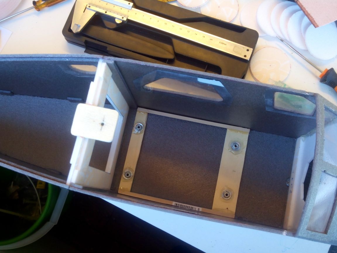
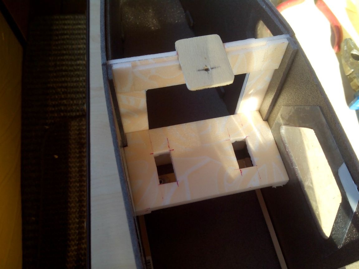
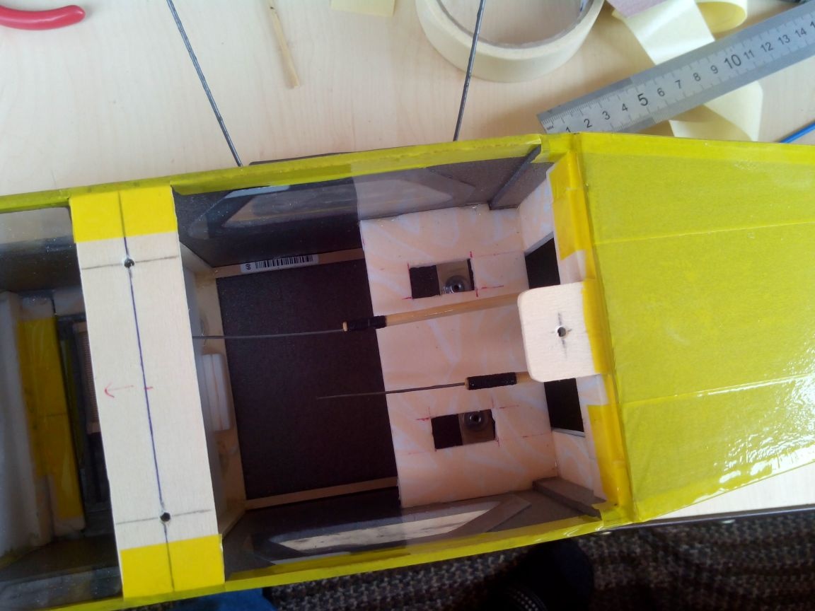
We glue the bases of the landing gear from plywood and rulers.
We drill holes in it, screw in the bolts with nuts and fill the nuts with epoxy.
We glue the base of the chassis and the rear platform for attaching the wing.
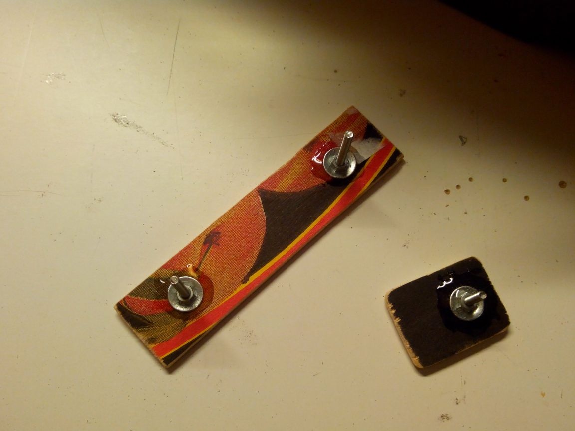
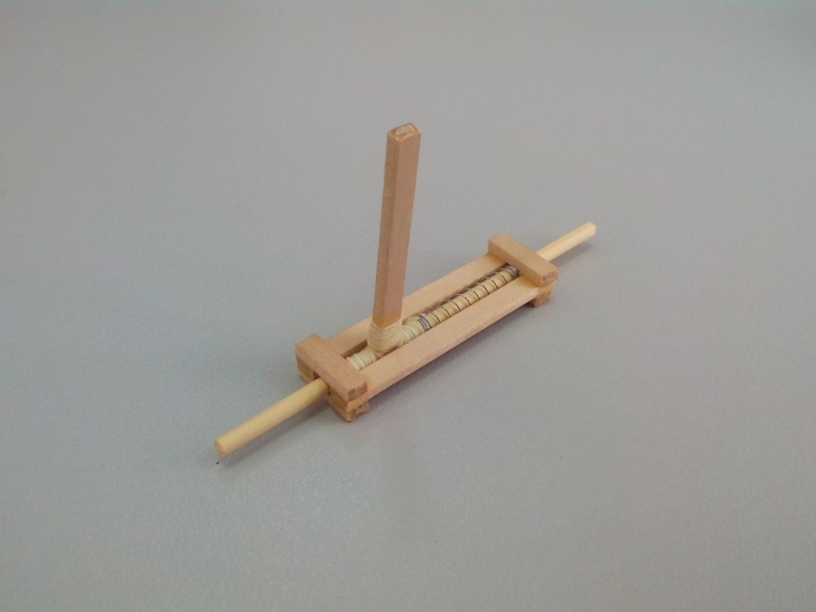
While all this dries, we make a latch for the battery hatch from rulers, a bamboo stick and a spring (I have already described its manufacture).
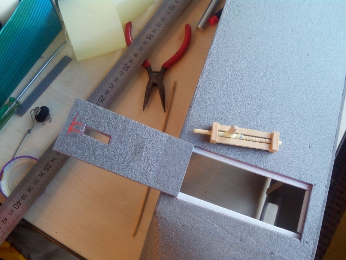
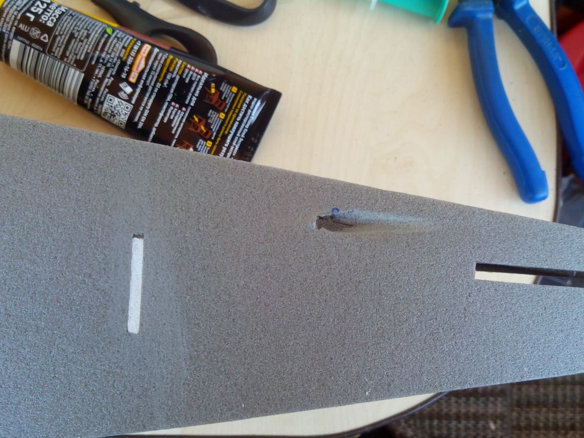
The access hatch for the battery is cut out at the bottom of the fuselage, in front of the base of the chassis.
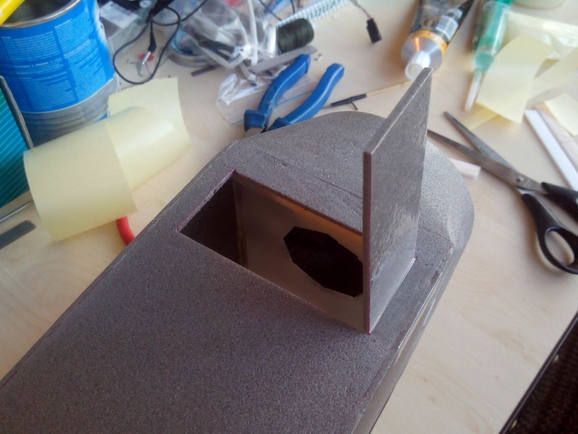
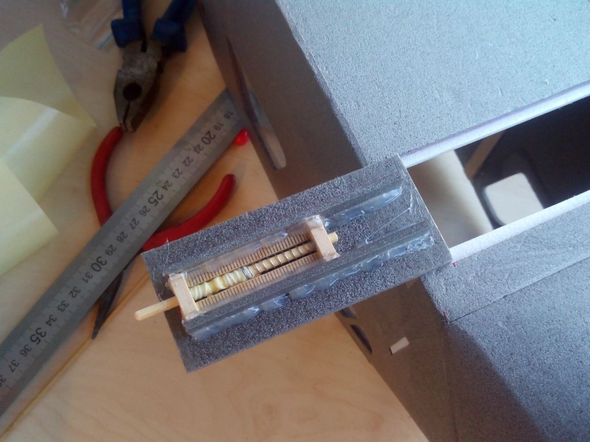
Inside the strips of the ceilings, glue the frame so that the lid does not fall through, and glue the latch.
Reinforce the lid with strips of depron and hot-melt adhesive.
Under the wing inside the fuselage, we glue the platform for the tail servos (two layers of ceiling tiles).
From the base of the chassis vertically glue two rods (from the ruler), to which the wing pad will then be glued, and glue the partition of the battery compartment.
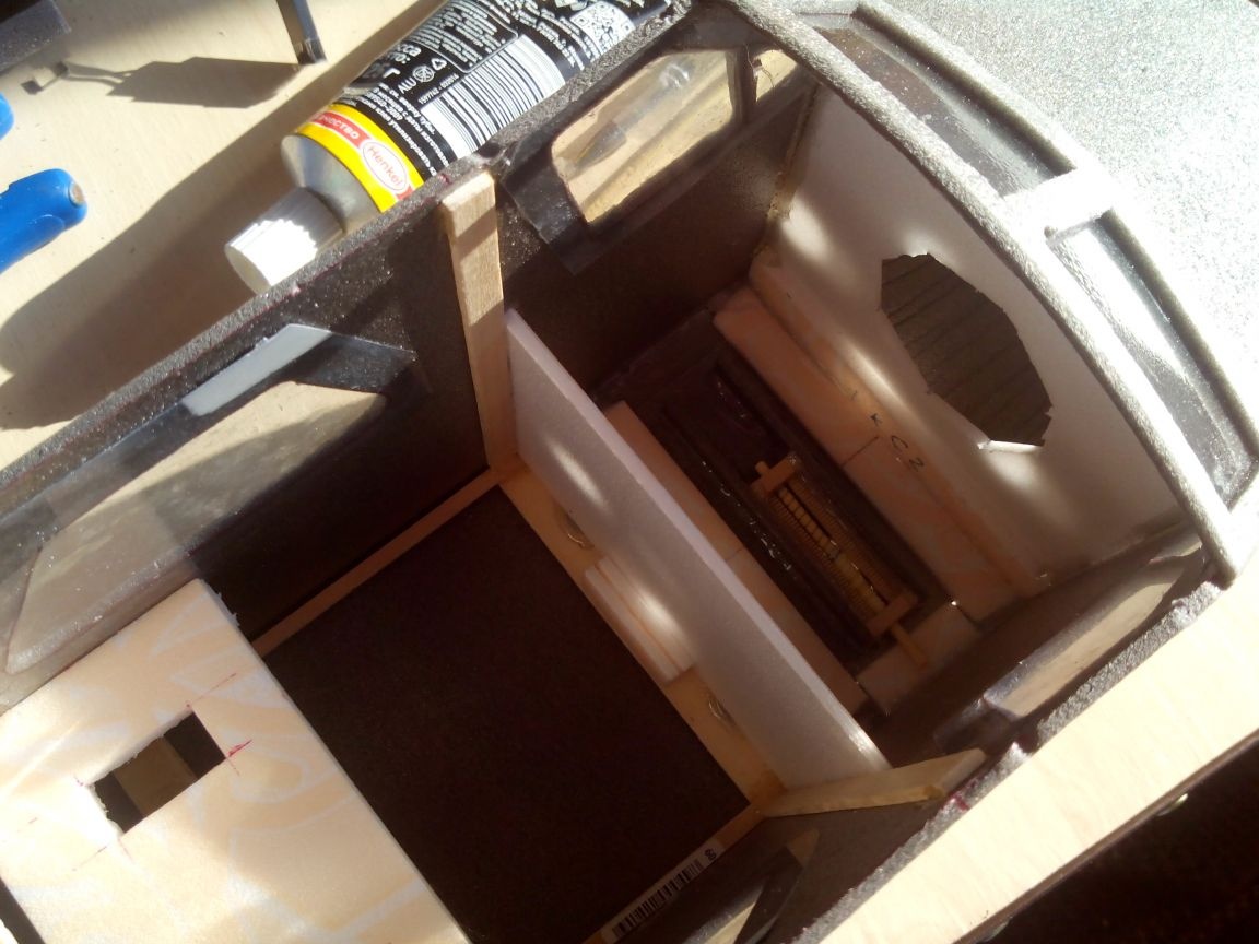
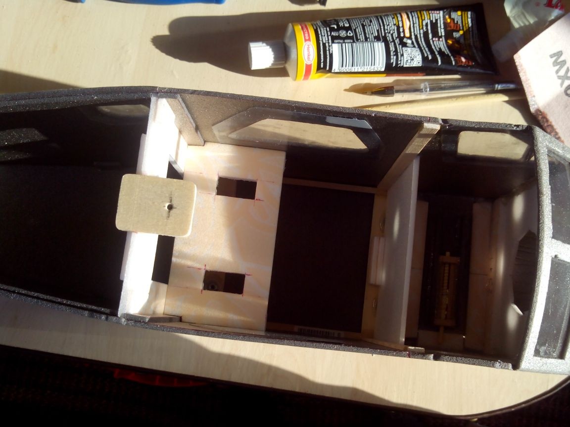
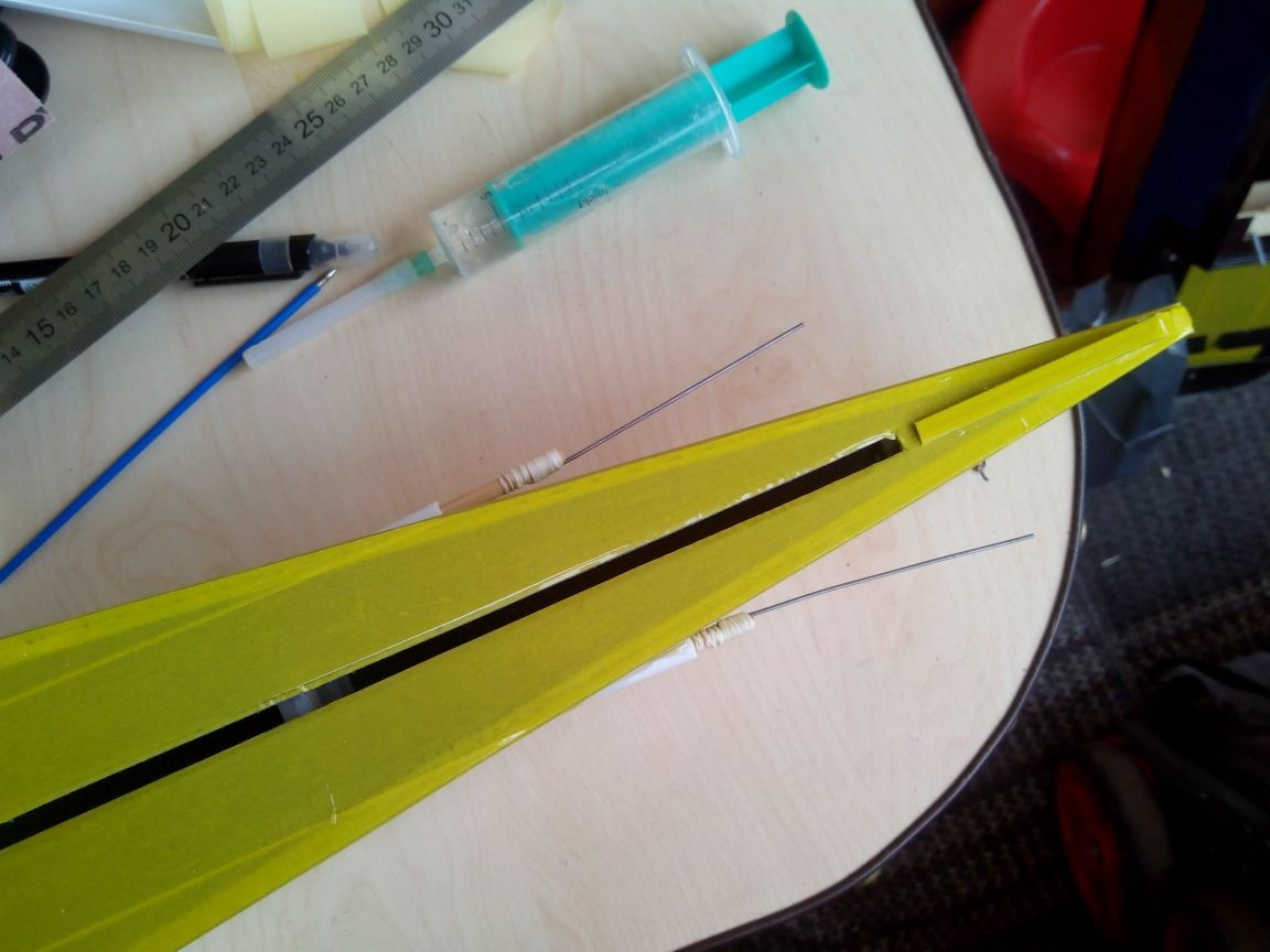
With an awl and a file, we make holes for the bowden.
We make rods of bamboo skewers and steel wire with threads and glue, after having planted bowden sticks from balloons on them.
We glue the rear landing gear onto the epoxy in the tail of the fuselage, made a slot in the bottom.
We seal the top of the tail.
Glue the pad under the wing.
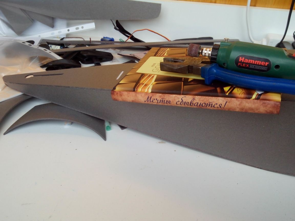
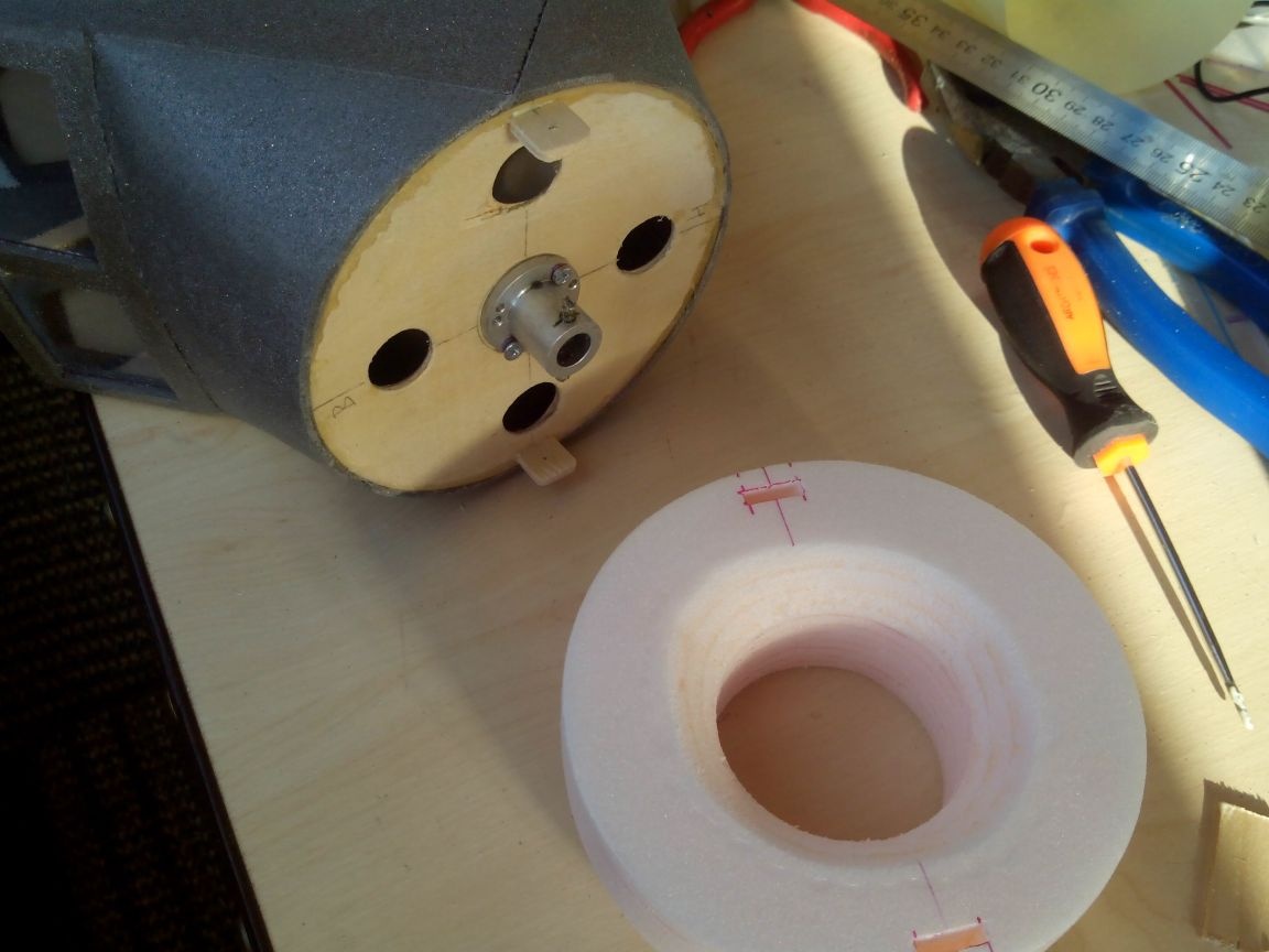
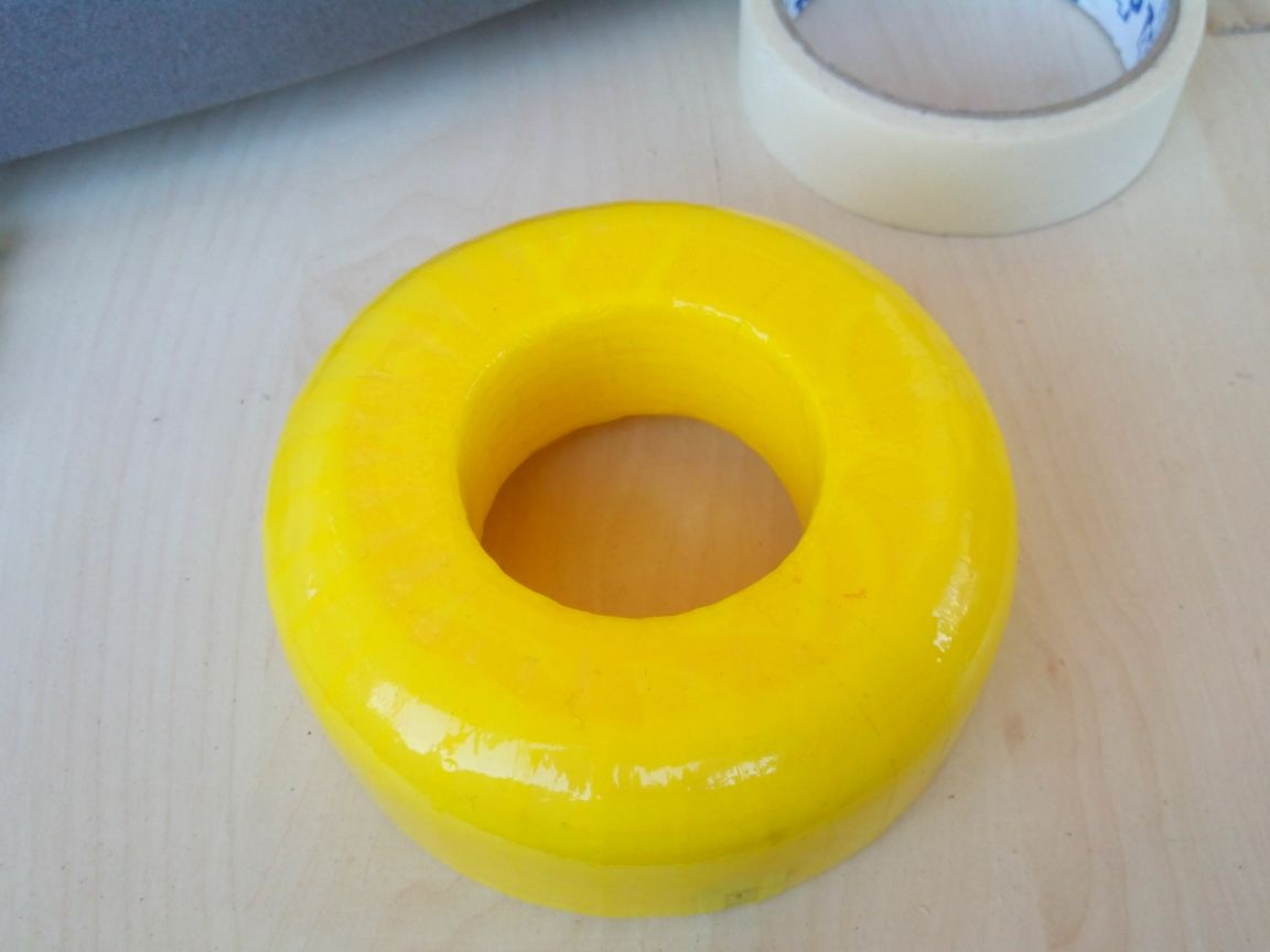
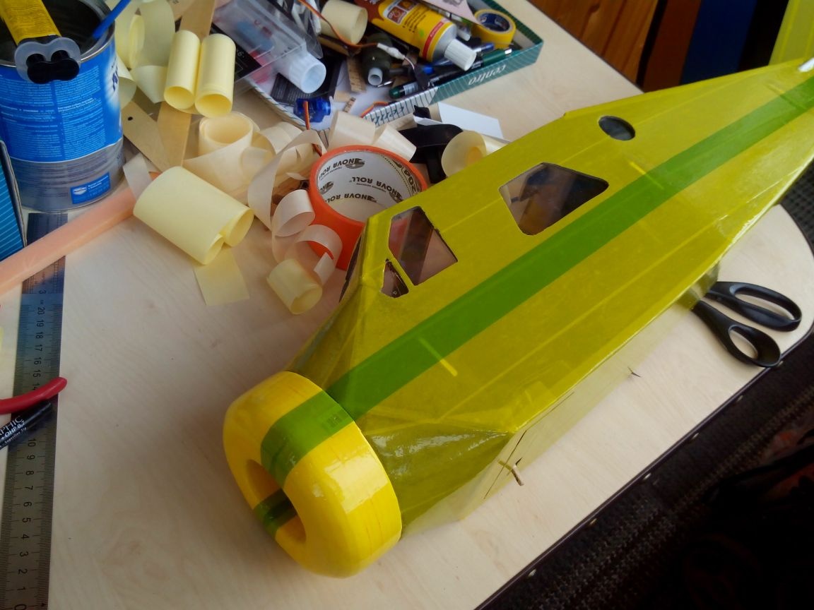
The hood was decided to redo a little.
So, we draw hood details on the ceiling sheet (12 rings with an outer diameter along the nose of the fuselage).
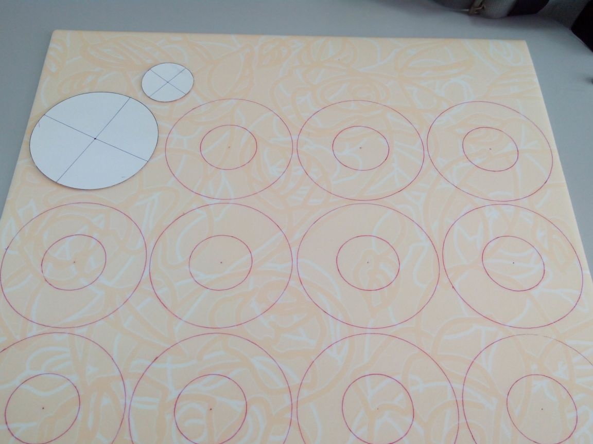
We glue the rings into one big "donut".
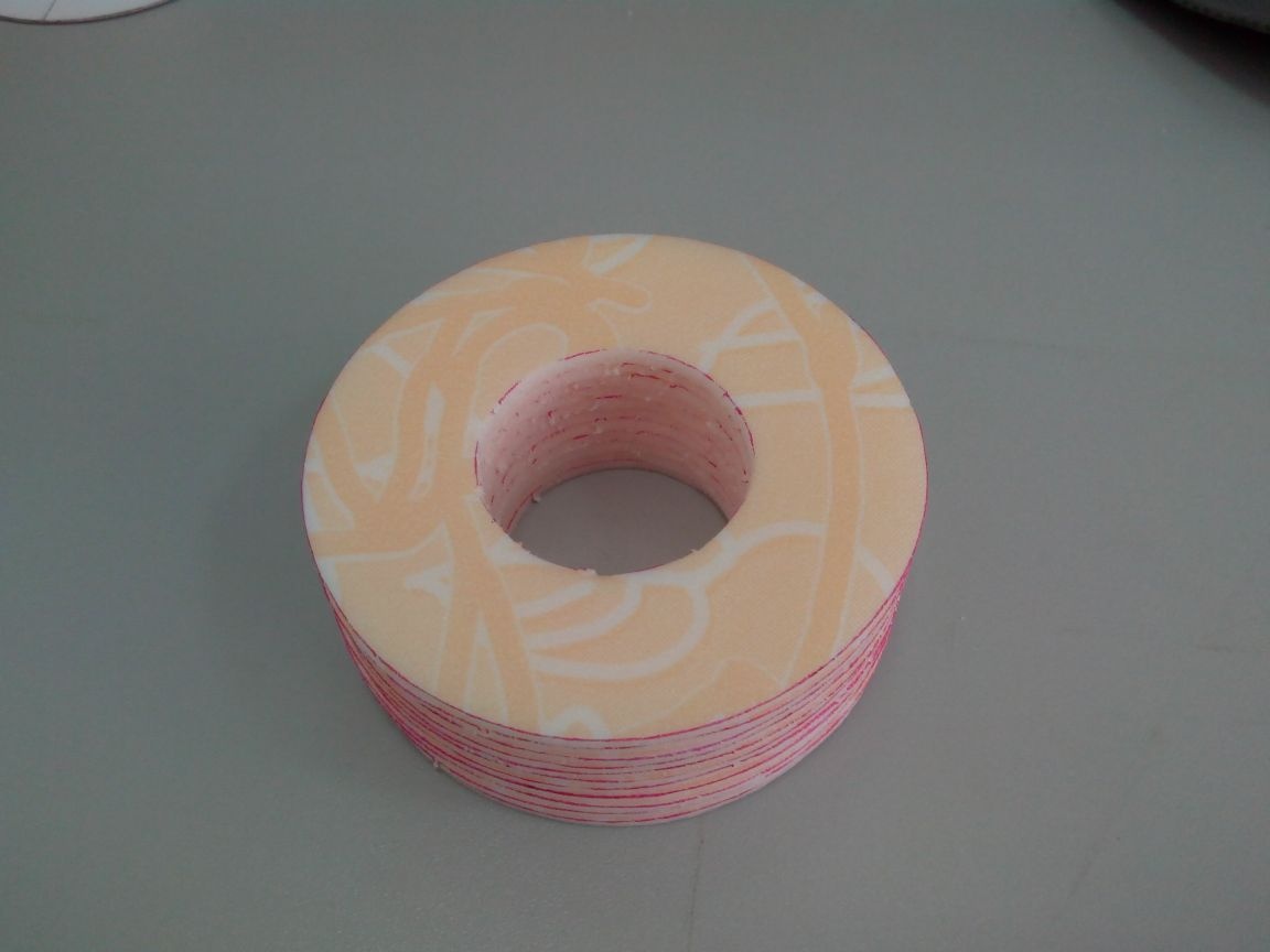
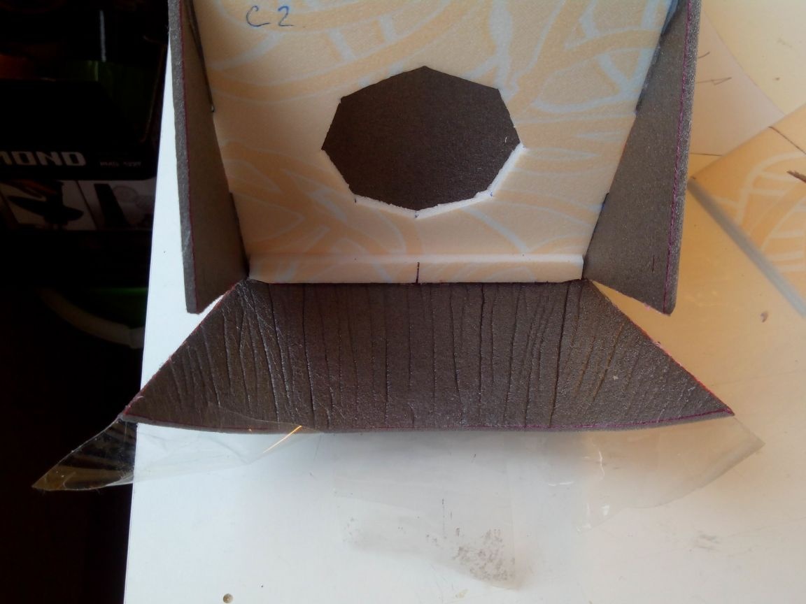
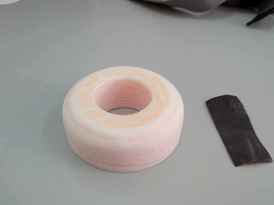
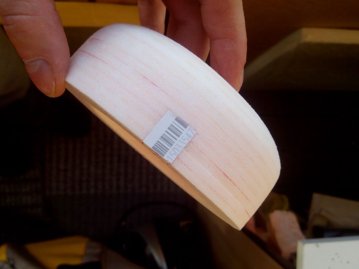
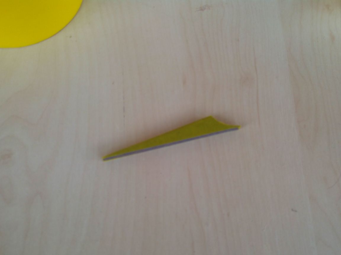
We cut the hood with a sharp knife at 45 degrees.

We process sandpaper.
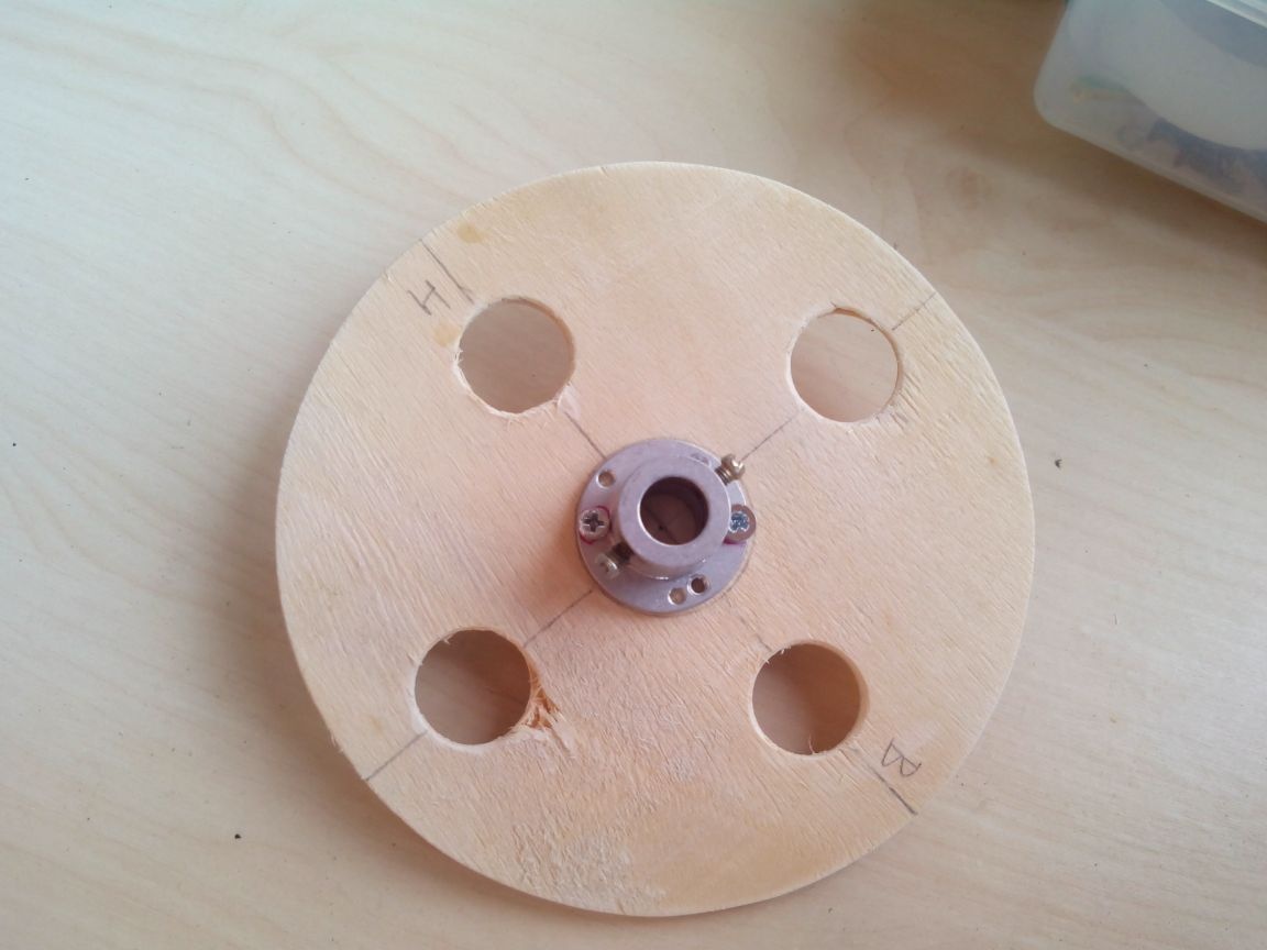
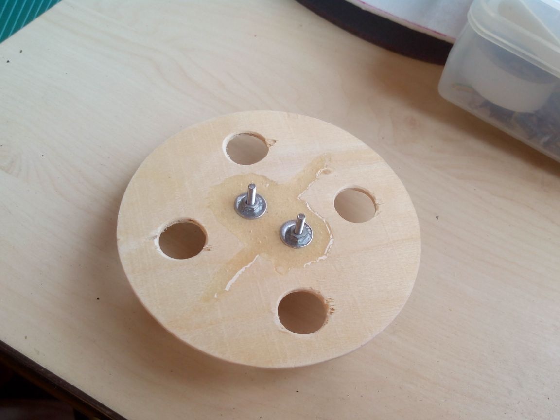
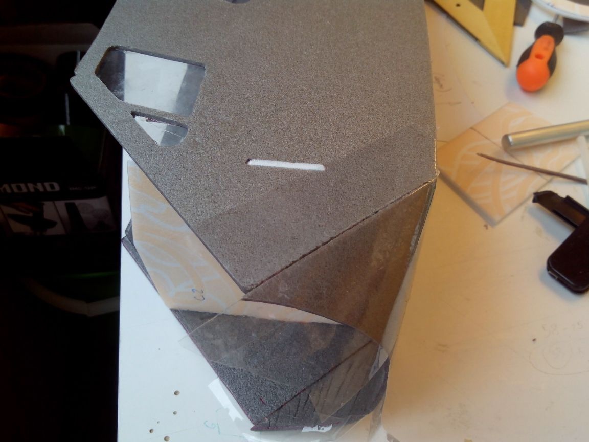
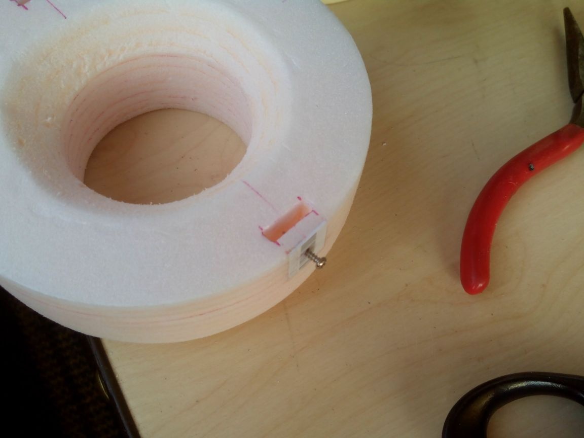
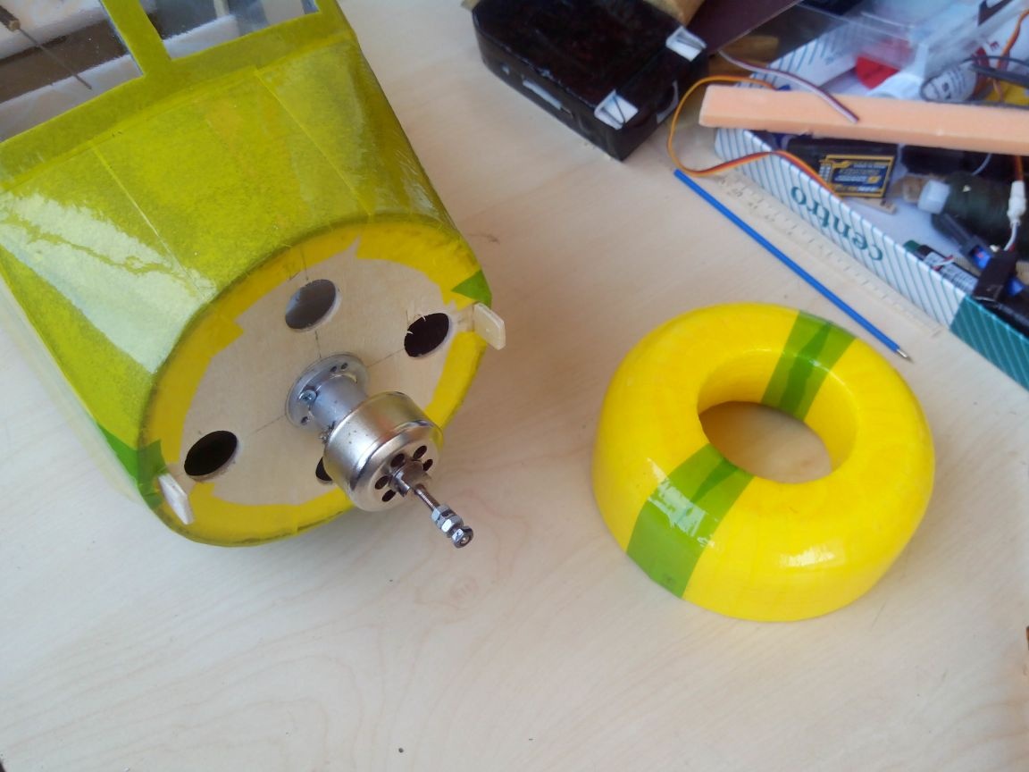
We cut out two bosses from plywood, to which the hood will be screwed, and we make holes for small screws in them.
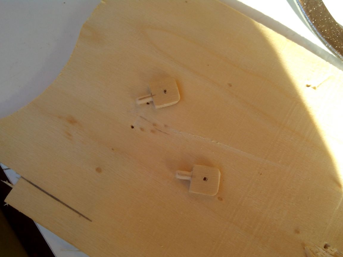
In the engine mount, drill holes for bosses and paste them there on PVA glue. And in the hood with a knife we make two blind holes for the bosses.
We strengthen the places for screws with pieces of plastic that are glued with epoxy.
We glue the hood with adhesive tape to match the color of the fuselage. It is more convenient to glue with narrow stripes, with an overlap.
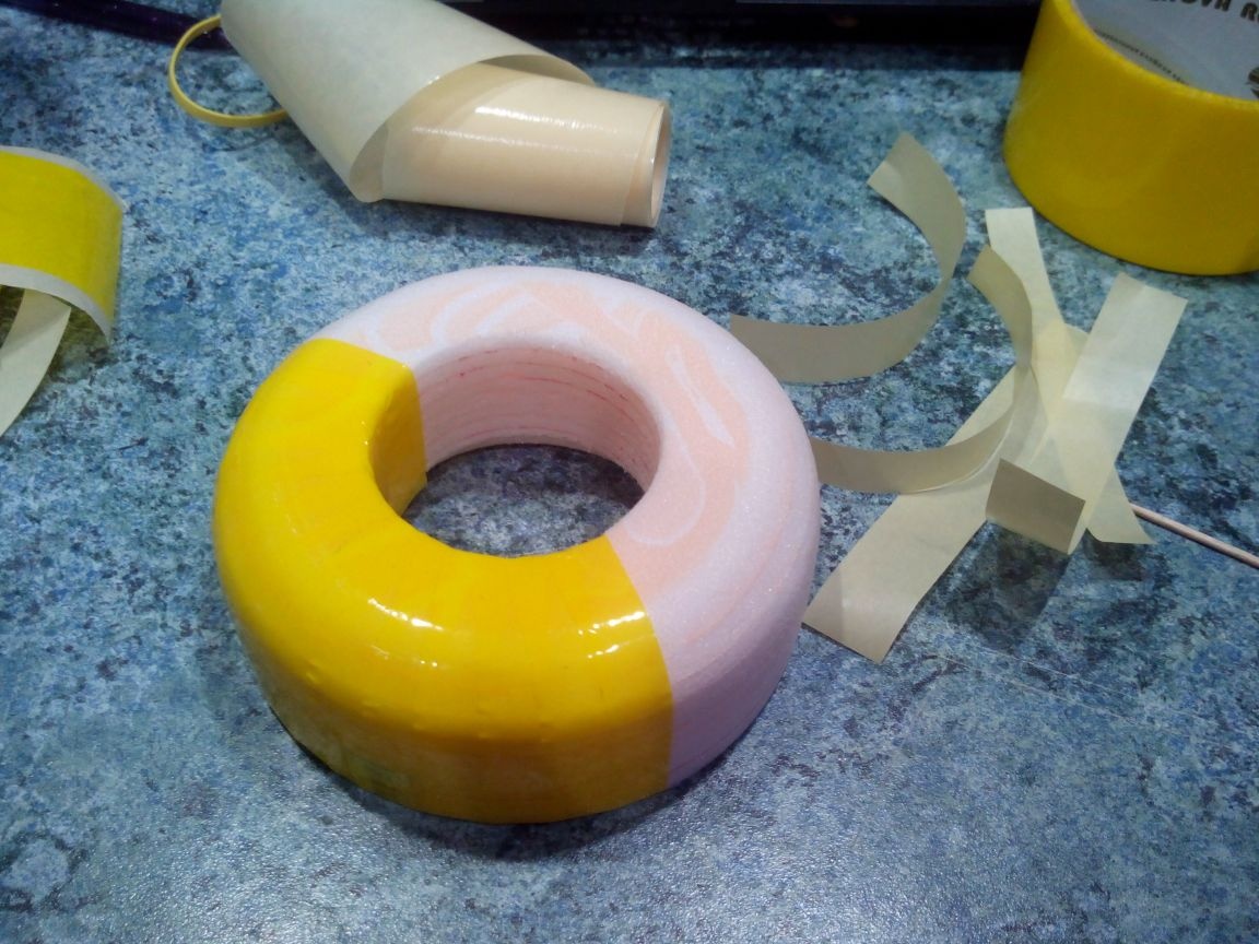
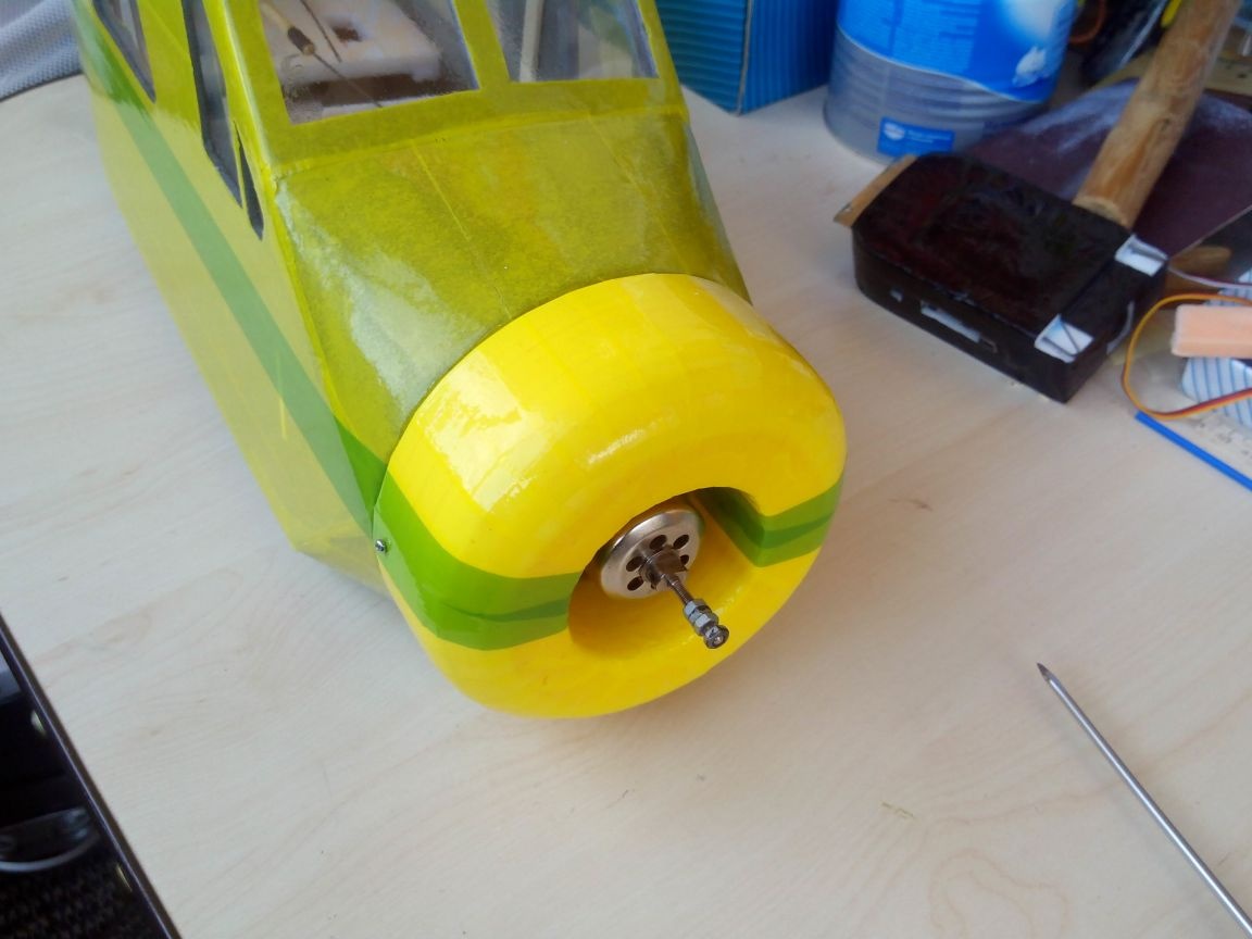
The hood is ready.
We proceed to gluing the fuselage with tape.
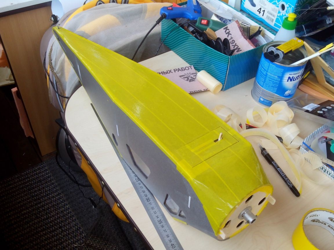
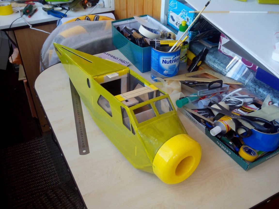
We decorate the sides of the fuselage and the hood with strips of adhesive tape.
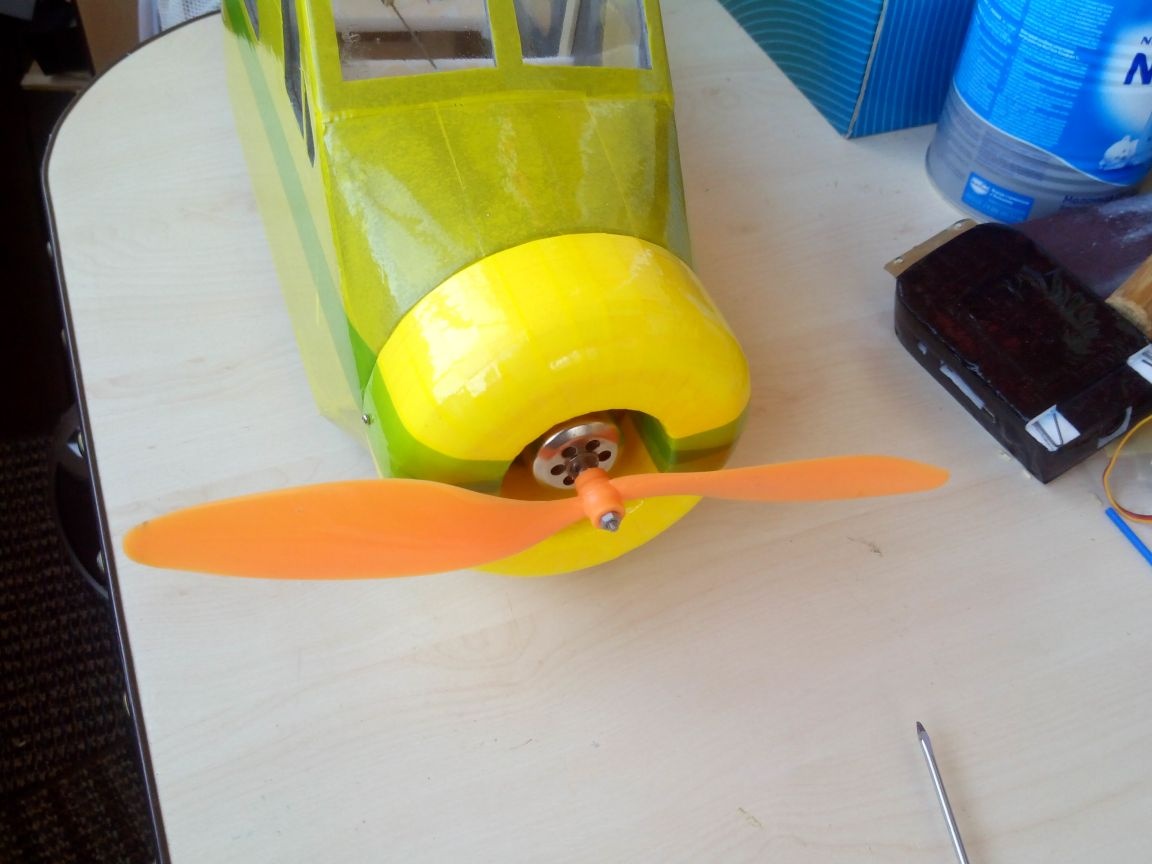
We fasten the motor.
We fasten the hood.
Fasten the screw.
We fasten the chassis.
We glue the bowden with the tail rods.
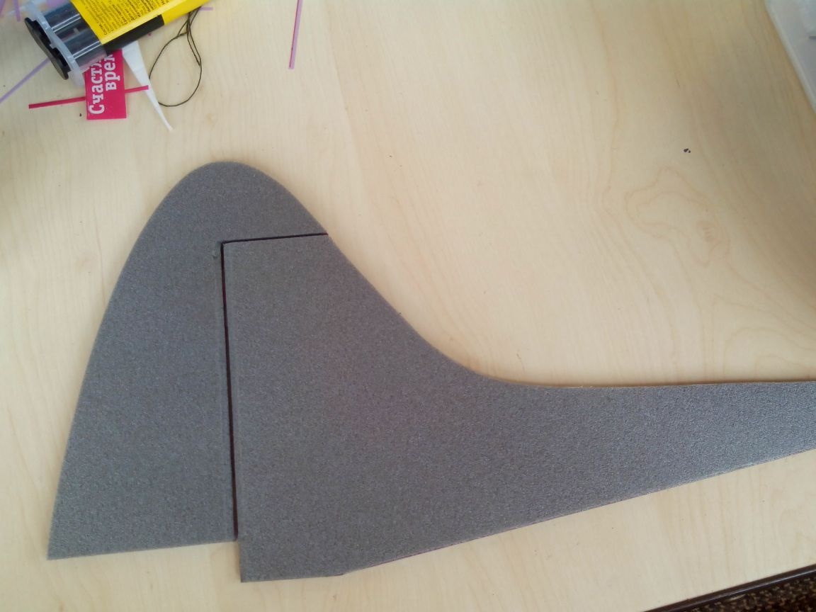
Step 5. The tail.
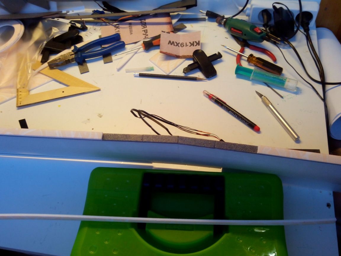
We mark on the debris sheet the details of the tail.
Cut the parts with a cutter.
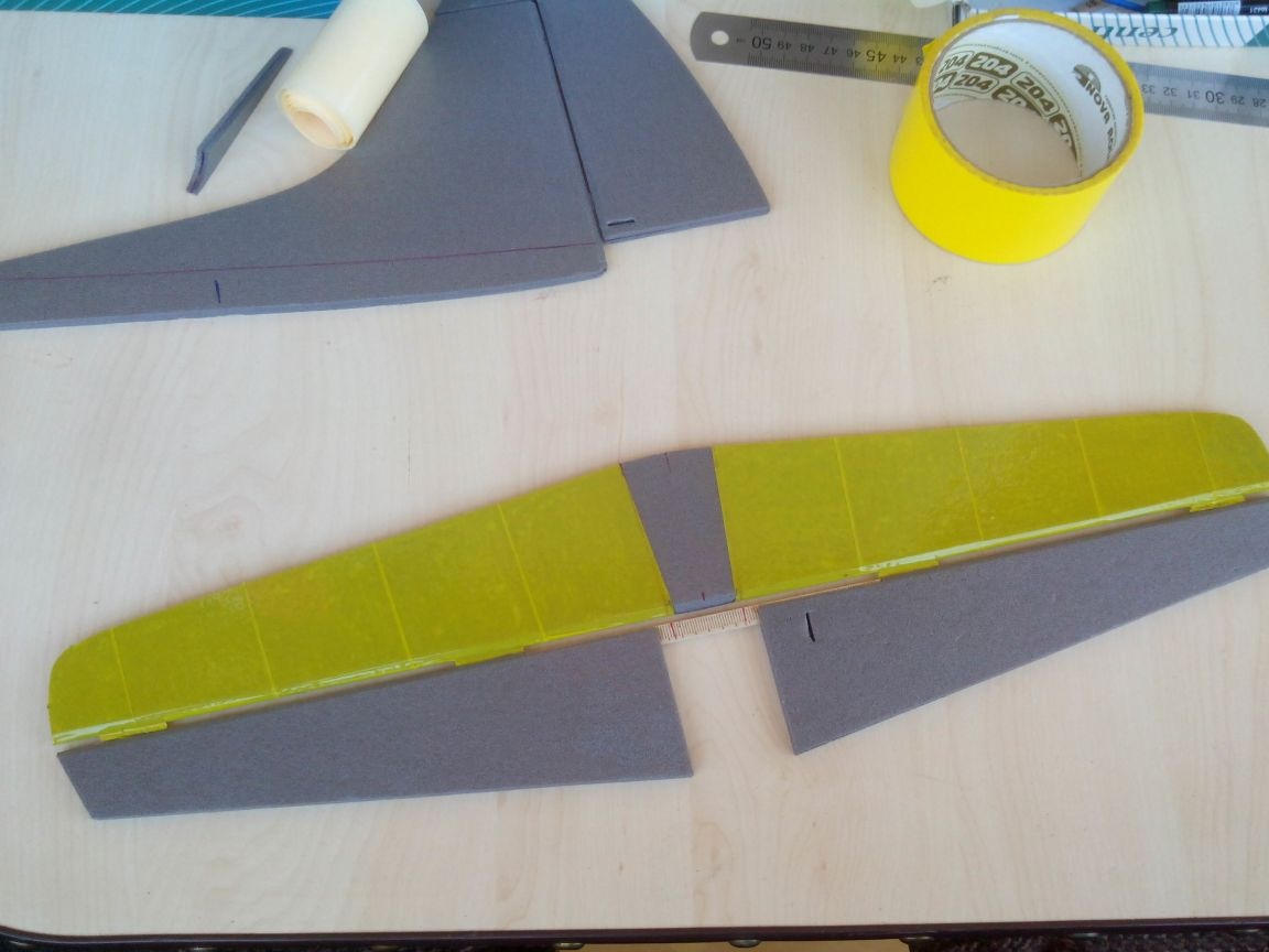
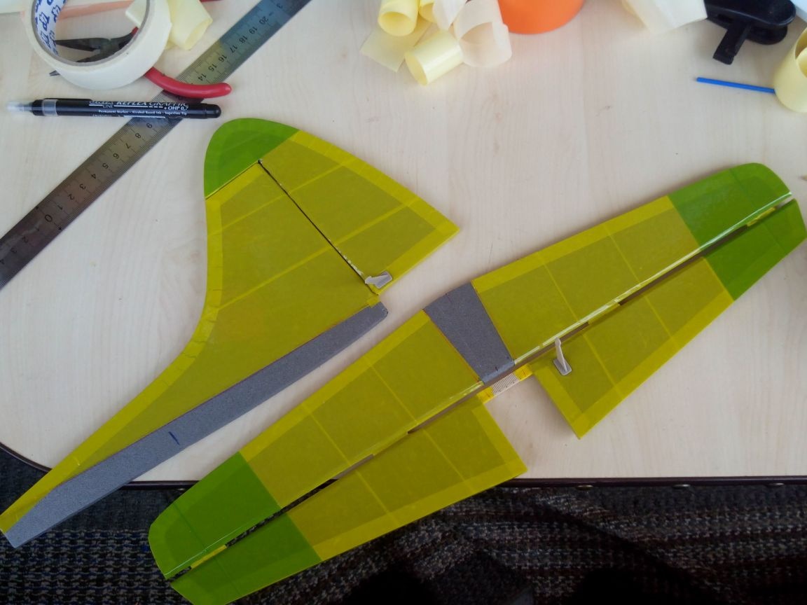
We connect the halves of the elevator with a rack from the ruler, having previously made depressions in the depressor parts for half the thickness of the rail.
Glue the hinges out of plastic (similar to the ailerons) and glue the top of the elevator. The photo shows the strips of depron, which are inserted between the stabilizer and the elevator - they are needed for more accurate gluing, so as not to distort the steering wheel.
It remains only to glue the second part of the stabilizer.
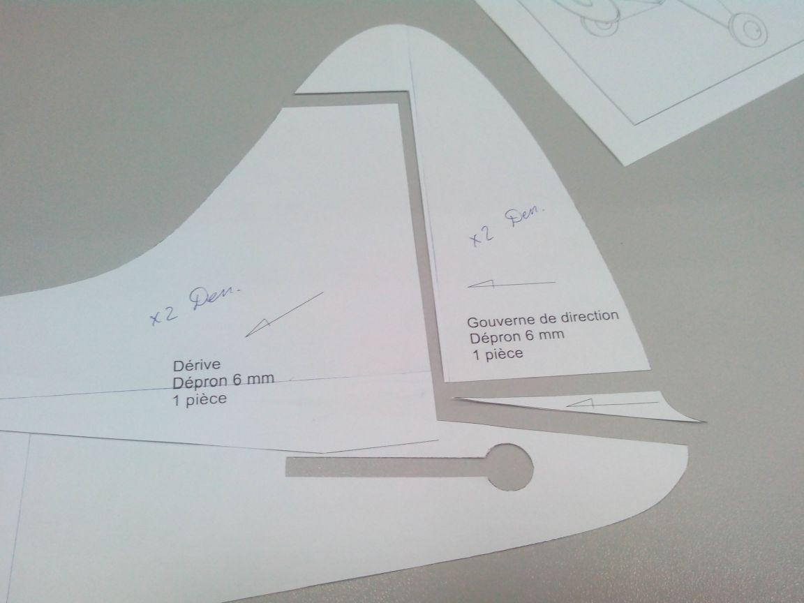
Similarly, do the keel and rudder.
We glue the stabilizer with tape.
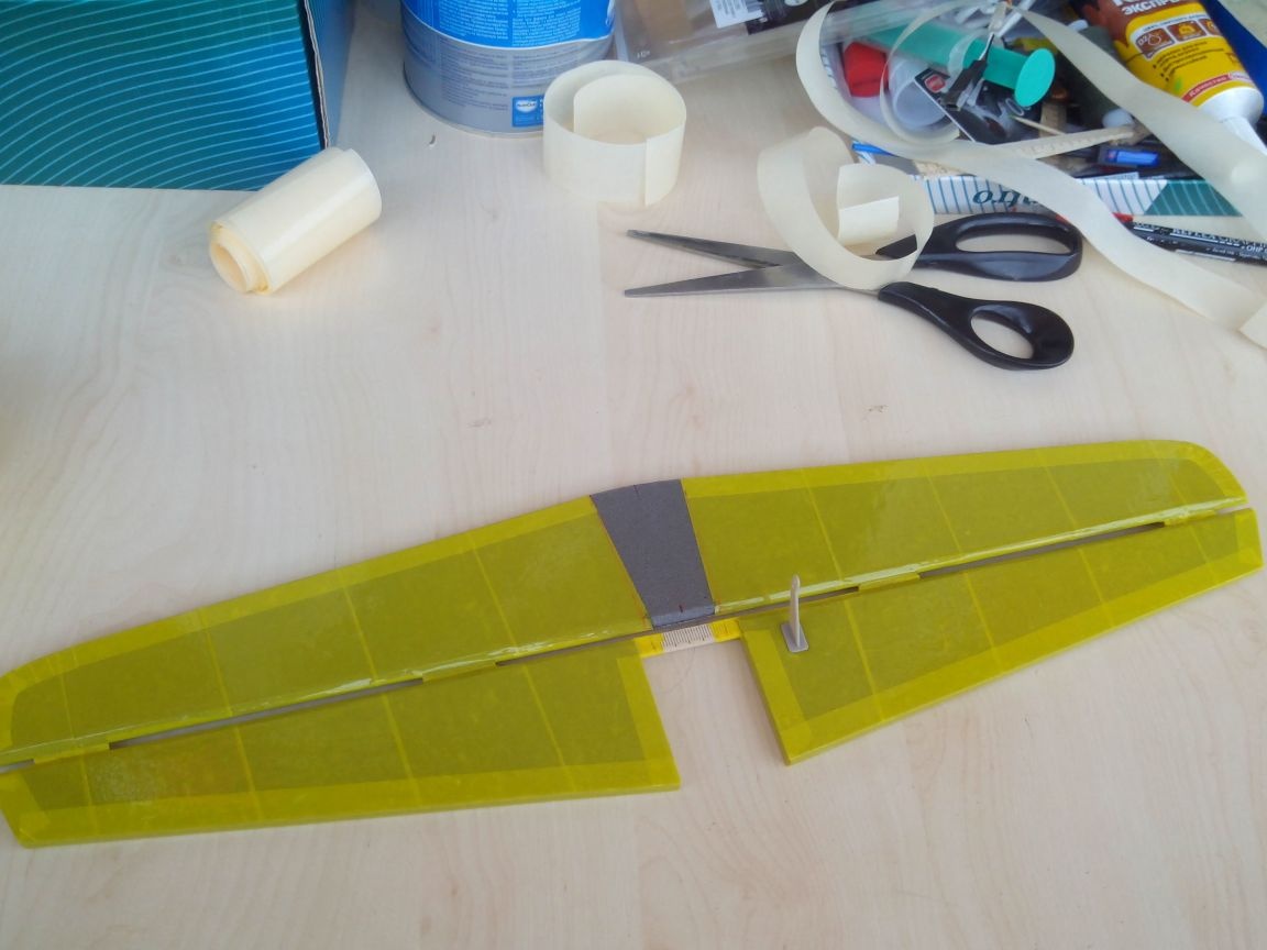
We glue the keel and rudder and a small detail under it (I never realized what it is called).
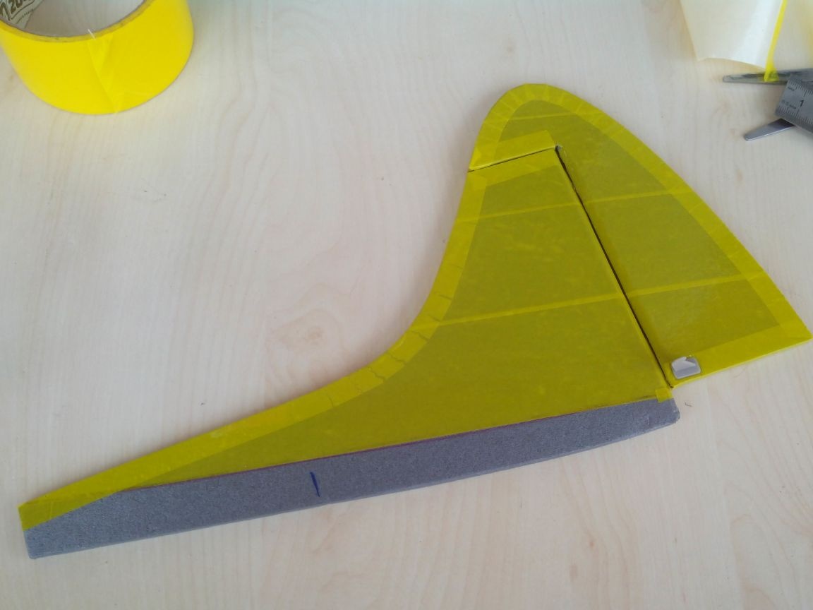
We decorate the tail in a different color and glue the boars.
We glue the stabilizer in the fuselage, and then the keel.
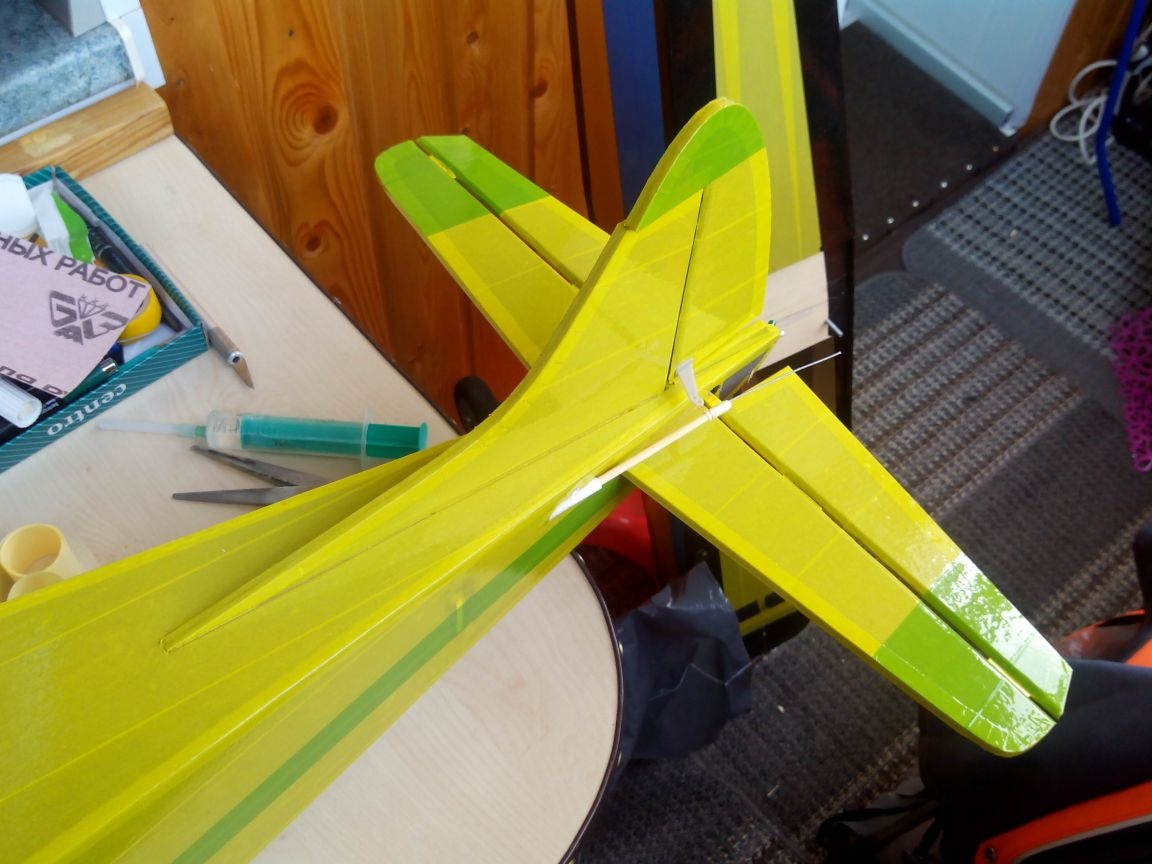
We fix the rods outside
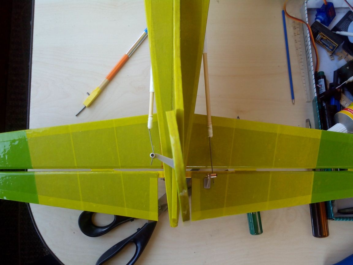
Large - detail under the rudder.
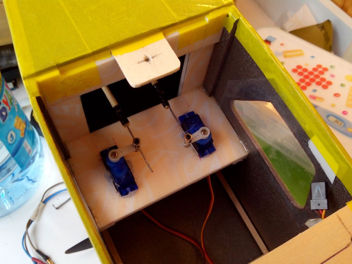
We glue the tail feather servos into the fuselage and fix the traction inside.
Step 6. Build the model, weigh and fly around.
We connect the wires from the motor and the regulator, connect to the receiver. We connect all the wires from the servos and put them in the cab.
We fasten the wing with bolts.
We connect the battery and close the lid.
Check the alignment.
I will touch on such a thing as the weight of the model:
Wing - 140 grams
Fuselage + motor - 340 grams
Regulator, battery and receiver - 140 grams
Total the flight weight of the model is 620 grams.
Flight Video: