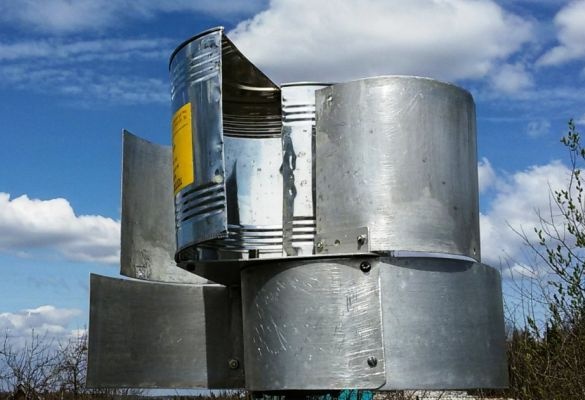
To drive the wind generator, a rotor-type turbine with a vertical axis of rotation is manufactured. This type of rotor is very strong and durable, has a relatively low rotation speed and can easily be made in home conditions without gimp with the aerodynamic profile of the wing and other problems associated with the manufacture of the propeller for a wind generator with a horizontal axis of rotation. Moreover, such a turbine operates almost silently and regardless of where the wind blows. The work is practically independent of turbulence and frequent changes in the strength and direction of the wind. The turbine is characterized by high starting torques, operation at relatively low speeds. The efficiency of this turbine is small, but this is enough to power devices of low power, everything pays off with the simplicity and reliability of the design.
Electric generator
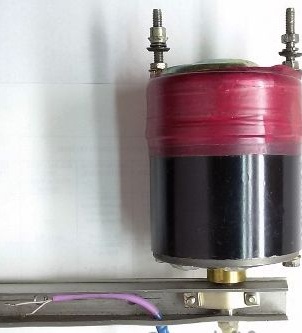
As a generator, a modified compact permanent starter car starter is used. Generator output: alternating current with a power of 1.0 ... 6.5 W (depending on wind speed).
A variant of converting a starter into a generator is described in the article: Alternator from starter
Making a wind turbine
This wind turbine is practically worthless and easy to manufacture.
The turbine design consists of two or more half cylinders mounted on a vertical shaft. The rotor rotates due to different wind resistance of each of the blades turned to the wind with different curvatures. The rotor efficiency is slightly increased due to the central gap between the blades, as a certain amount of air additionally acts on the second blade when leaving the first.
The generator is fixed on the rack for the output shaft, through which the wire with the received current comes out. This design eliminates the sliding contact for the removal of current. The turbine rotor is mounted on the generator housing and fixed on the free ends of the mounting studs.
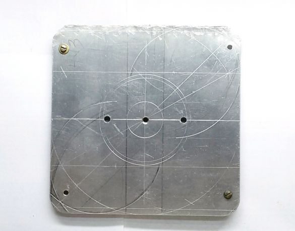
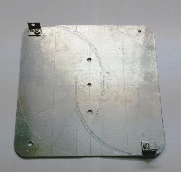
A disk with a diameter of 280 ... 330 mm or a square plate inscribed in this diameter is cut out of an aluminum sheet 1.5 mm thick.
Regarding the center of the disk, five holes are marked and drilled (one in the center and 4 in the corners of the plate) for installing the blades and two holes (symmetrical to the center) for fixing the turbine to the generator.
In the holes located at the corners of the plate, small corners of aluminum are installed, with a thickness of 1.0 ... 1.5 mm, for fixing the blades.
We make turbine blades from a can with a diameter of 160 mm and a height of 160 mm. The jar is cut along the axis in half, resulting in two identical blades. The edges of the can after the cut, at a width of 3 ... 5 mm, are bent by 180 degrees and crimped to strengthen the edges and eliminate sharp cutting edges.
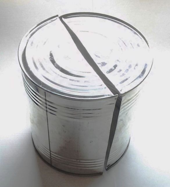
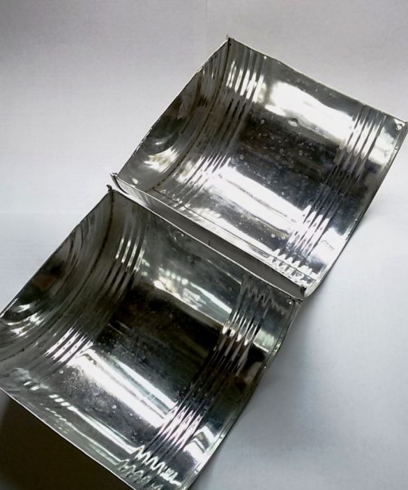
Both turbine blades, from the side of the open part of the can, are interconnected by a U-shaped jumper with an opening in the middle. The jumper forms a gap 32 mm wide, between the central part of the blades, to increase the efficiency of the rotor.
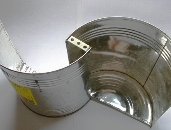
On the opposite side of the can (at the bottom), the blades are interconnected by a jumper of minimum length. In this case, a gap of 32 mm width is maintained along the entire length of the blade.
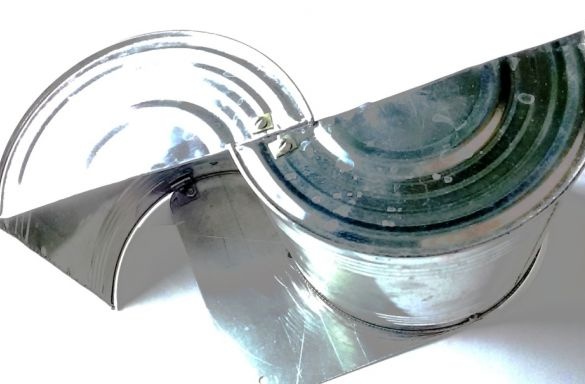
The assembled block of blades is mounted and mounted on the disk at three points - for the central hole of the jumper and the previously installed aluminum corners. The turbine blades are fixed on the plate strictly one against the other.
To connect all parts, you can use rivets, self-tapping screws, screw connection M3 or M4, angles or apply other methods.
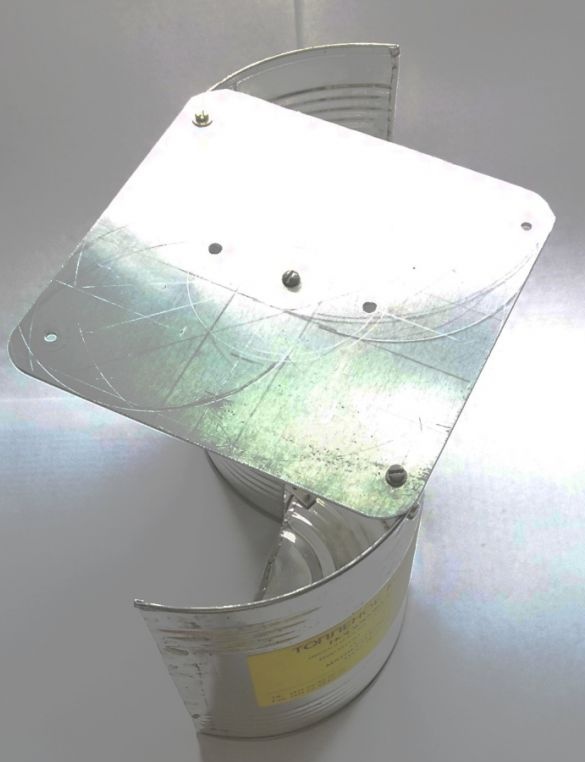
A generator is installed in the holes, on the other side of the disk, and fixed with nuts on the free ends of the mounting studs.
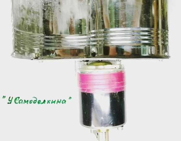
For reliable self-start of the wind generator, it is necessary to add a second similar tier of blades to the turbine. In this case, the blades of the second tier are shifted along the axis relative to the blades of the first tier by an angle of 90 degrees. The result is a four-blade rotor. This ensures that there is always at least one blade that is able to catch the wind and give the turbine a boost to rotate.
To reduce the size of the wind generator, the second tier of the turbine blades can be made and fixed around the generator. We make two blades 100 mm wide (generator height), 240 mm long (similar to the length of the first tier blade) from an aluminum sheet 1.0 mm thick. Bend the blades along a radius of 80 mm, similar to the blades of the first tier.
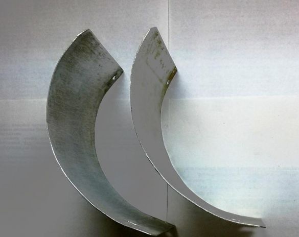
Each blade of the second (lower) tier is fixed using two corners.
One is installed in a free hole on the periphery of the disk, similar to the fastening of the upper tier blades, but with a 90-degree shift. The second corner is fixed to the pin of the installed generator. In the photo, for clarity, the mounting of the lower tier blades, the generator is removed.
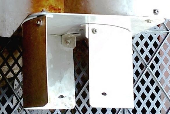
For structural strength, after general assembly, both blades of the lower tier, through holes in the lower part of the blades, are additionally attracted to the generator by a wire clamp.
After assembling the turbine and installing it on the generator, this design turned out:
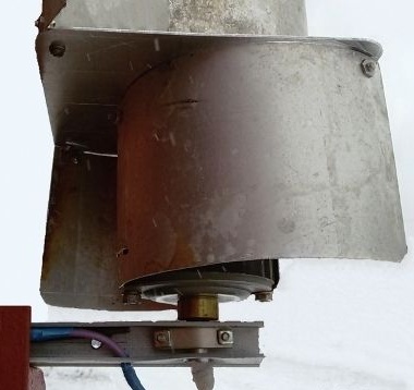
Tests conducted in nature have shown that the design of the wind generator is functional, but does not start well at low wind speeds. Therefore, on the upper tier of the turbine blades, in addition to the two available, two more blades are added (similar to the existing ones) or from an aluminum sheet 1.0 mm thick, similar in design and size. The lower tier blades are somewhat elongated to increase the starting torque.
Wind turbine operation video

