There are many cases when living outside the city, you may need a small amount of electricity to power a low-power device. For example, for the operation of a compact weather station, monitoring the water level in a tank, controlling the automation of a greenhouse, for emergency lighting of a garden path or a small room and other devices. For each of them it is necessary to have a power source - a battery, a battery or a network power supply (PSU). In case of periodic load of the device, it is advisable to use a battery-powered PSU. Moreover, for charging it, using the device under these conditions, it is most beneficial to use renewable wind energy, which will make the PSU economical and autonomous.
In our case, we will consider the option of using wind energy for emergency lighting of a garden toilet, standing separately on the edge of the plot. Since bright lighting at this object is not necessary, then low power is sufficient to solve this problem. During the day, the battery is charged by wind energy, and in the dark gives it as needed.
To make a power supply, a wind generator with a power of several watts, a small-capacity battery and a charger for it, a voltage matching device will be required.
Wind generator
As an electric generator, a modified compact permanent starter car starter is used. Generator output: alternating current with a power of 1.0 ... 6.5 W (depending on wind speed). Voltage - 1 ... 6 v; current - 0.2 ... 1.1 a (in the range: small - average wind speed).
A variant of converting a starter into a generator is described in the article.
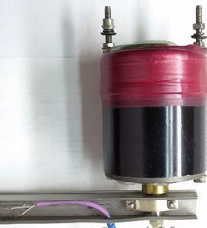
To drive an electric generator, a rotor type turbine with a vertical axis of rotation was made. This wind turbine costs almost nothing and can easily be made in home conditions. Moreover, such a turbine operates almost silently and regardless of where the wind blows. The efficiency of this turbine is small, but this is enough for the operation of this device. Everything is ensured by the duration of work and pays off by the simplicity and reliability of the design. A turbine manufacturing option is described in article

Battery and Charger.
As an energy storage device, a lithium-ion battery from a mobile phone is applicable. The scheme and manufacturing procedure of the charger (charger) for this battery are presented in article.
Input data of the charger: direct current voltage of 5.5 ... 30 V. The output voltage of the proposed charger in the range of 4.18 - 4.20 V. When using another battery, with appropriate adjustment, the charger allows you to get the output voltage within 2.5 ... 27 V.
Voltage Matching
The voltage and current from the wind turbine vary depending on the wind speed, so for practical use, we must be able to charge the battery and save energy for use there. For this, the electricity from the wind generator must be converted from alternating current to direct, with a voltage sufficient to operate the battery charger.
The proposed wind generator, as can be seen from the output characteristics, is not able to produce the necessary voltage due to the low speed. At an average wind speed, a voltage of about 2 ... 5 V can be obtained at the output, and a voltage of more than 5.5 volts is required to charge the battery. The way out is the use of a simple voltage converter, assembled on the basis of a four-fold voltage multiplier. By applying 2 ... 5 V of alternating current to the input of the converter, we get 5.5 ... 12 V of direct current at the output, which is quite enough to charge the battery. One of the variants of the fourfold voltage multiplier used in the proposed device is shown in the diagram.
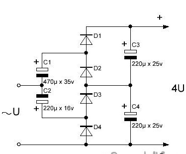
This version of the multiplier has a symmetrical design and good load capacity, made of cheap and affordable elements. The use of a multiplier, instead of a step-up transformer, reduces the size and weight of the device, eliminates the voltage rectifier.
As a result, the circuit of an autonomous power supply takes the following form.

The scheme consists of 4 blocks:
A1 - wind generator;
A2 - voltage multiplier;
A3 - battery and charger;
A4 - lighting unit.
Production of an autonomous power supply
1. Voltage multiplier (block A2), according to the above diagram, we assemble and solder on a 65 x 35 mm board cut out from a universal mounting textolite board.
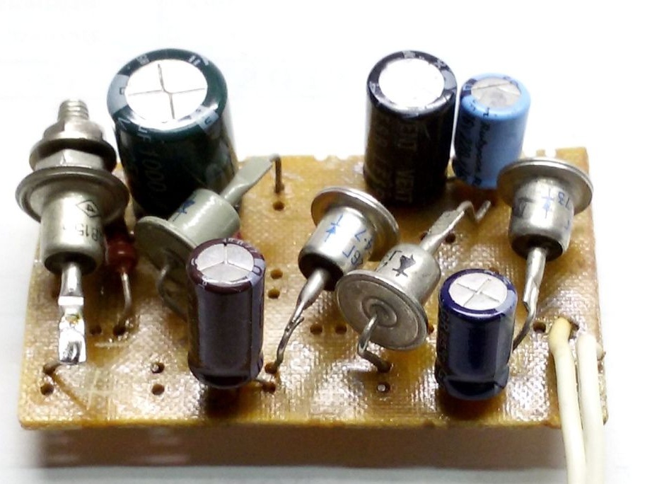
For mounting the circuit used previously unrealized domestic diodes D226G having an effective heat sink. Imported electrolytic capacitors. If necessary, it is possible to assemble this circuit more compactly using modern imported diodes with the lowest possible direct voltage to increase the efficiency of the voltage converter.
It must be taken into account that during operation of the device, the maximum current flowing through the diodes will be equal to twice the load current, and twice the amplitude value of the input voltage develops on electrolytes. Accordingly, capacitors and diodes must be designed for these parameters.
Additionally, a resistor R6 is added to the voltage multiplier block to limit the maximum current and a Zener diode D5 is used to limit the voltage. These elements should work to protect the device in high winds. To smooth the ripple, the output of the voltage multiplier is connected to electrolyte C5 (transferred to block A3 in the diagram).
2. Battery and Charger (A3). As an energy storage device, a lithium-ion battery from a mobile phone is applicable. The scheme and manufacturing procedure of the charger for this battery are presented in article.
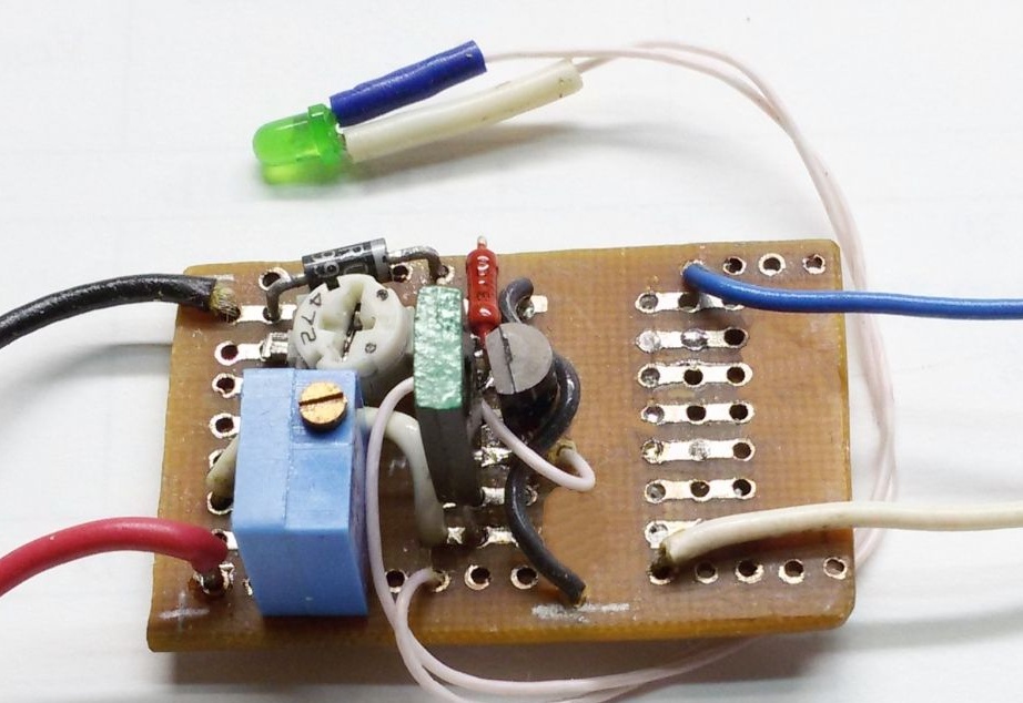
Setting the charging current of the circuit. Having connected the discharged battery to the circuit (as the LED turns on), we set resistor R2 to the charging current according to the tester - 100 ... 150 mA.
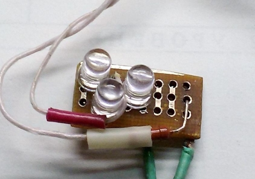
3. Lighting unit (A4) includes a circuit consisting of three serially connected superbright LEDs, a limiting resistor R5, and a power switch for the LEDs. The limiting resistor LEDs are mounted on a separate board.
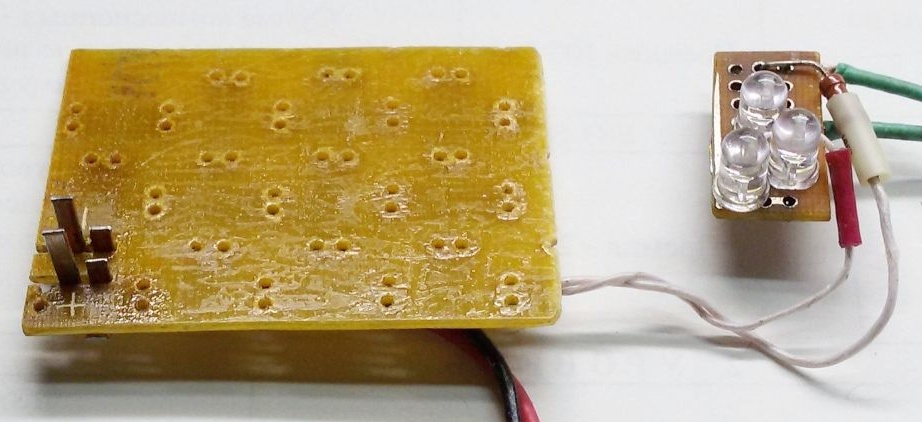
4. Let's make a board for installing a lithium-ion battery. We cut a rectangle of 40 x 55 mm from the universal mounting PCB; we cut two grooves in the board 0.7 ... 1.0 mm wide for installing contacts.The pin layout depends on the model of lithium-ion battery used. From a copper or brass plate with a thickness of 0.5 ... 0.7 mm, we cut out the L-shaped contacts and fix them on the back of the board using soldering or another connection. Solder the contacts to the corresponding output terminals of the charger and the lighting unit. On the board of this device, two groups of contacts of different heights are made for parallel connection of two batteries (to increase capacity) installed on top of each other.
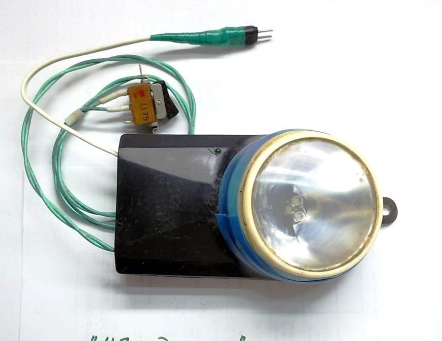
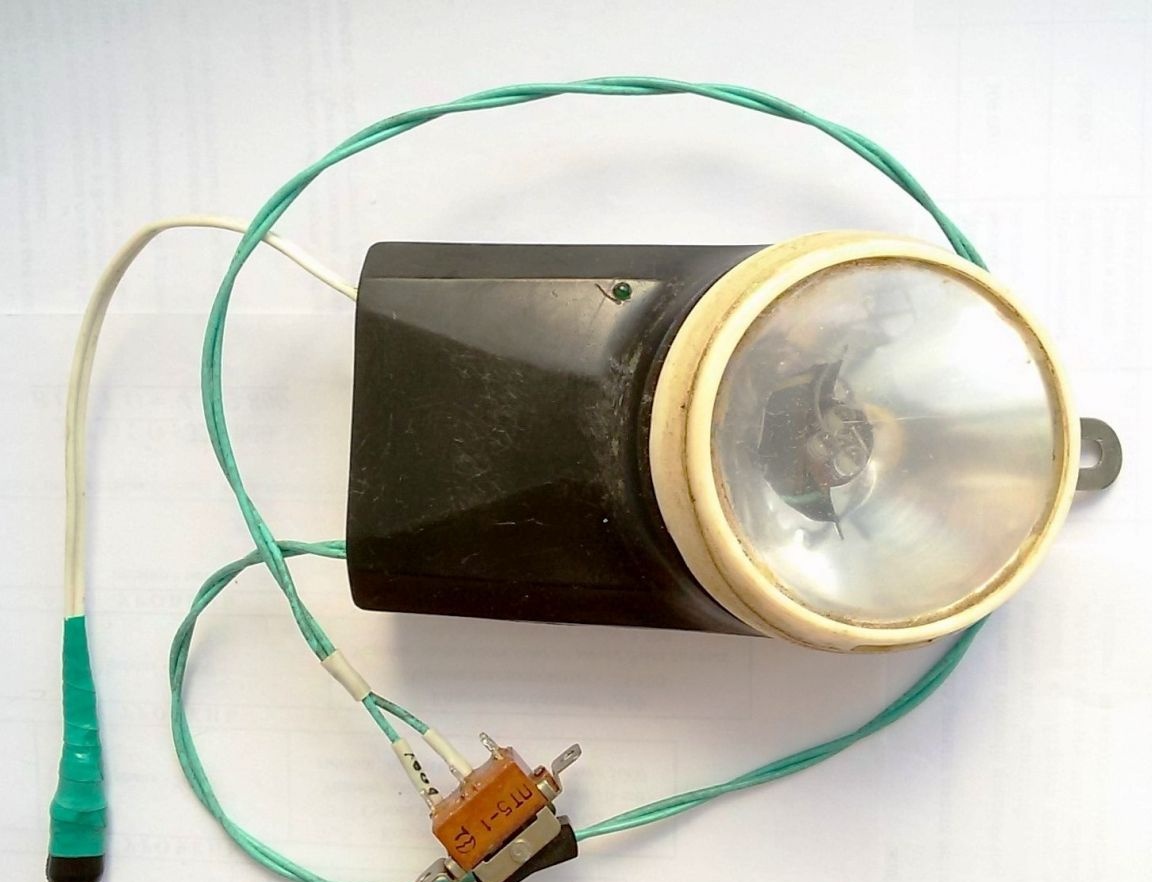
5. Power supply assembly. We assemble the manufactured blocks according to the above diagram, using the mounting wire. As a case, it is possible to use a box of suitable size, a lamp. Desirable in dust and waterproof design (work outdoors). In this case, the plastic case from the old flashlight was used.
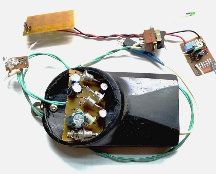
6. Checking the operation of the device.
At the input of the device we supply alternating current with a voltage of 2.3 V.
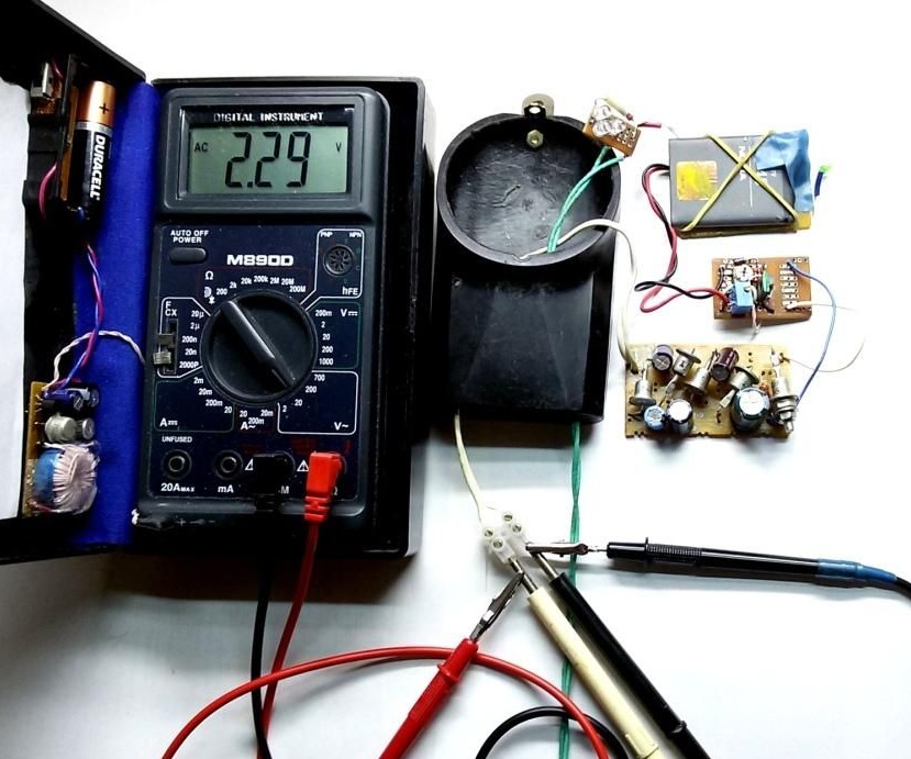
At this voltage, at the output of the multiplier we get a direct current voltage of 6.43 V.
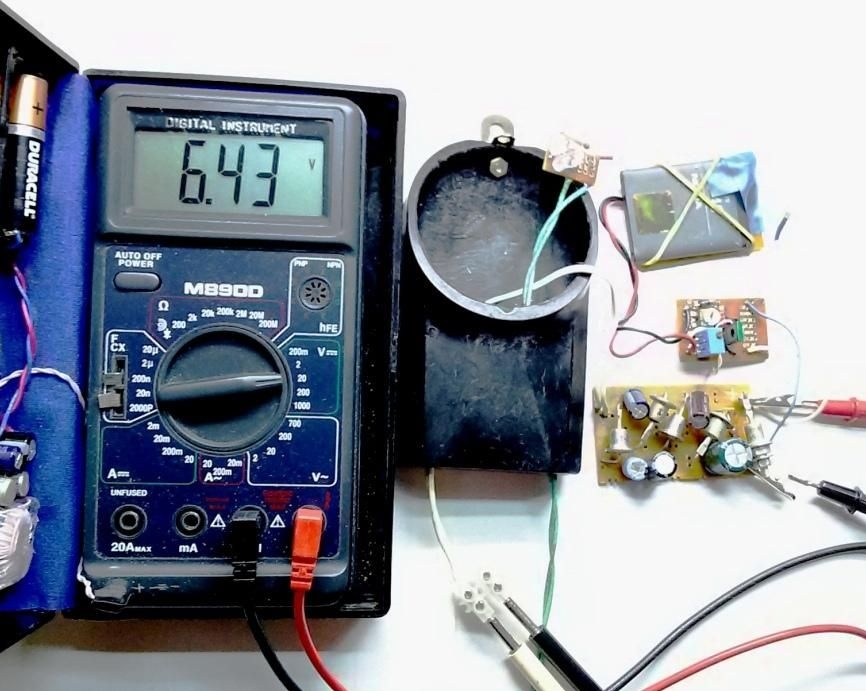
We check, if necessary, adjust the output voltage of the charger.
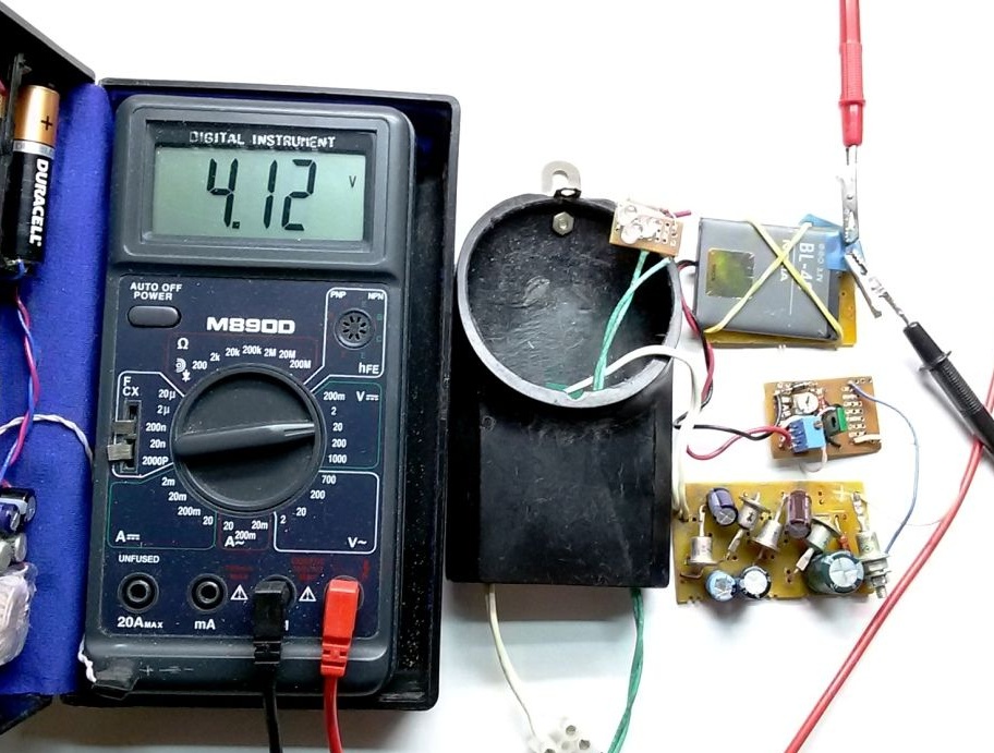
We are convinced of the correct operation of the manufactured device.
7. Install the assembled blocks in the case. We fix the battery charge indicator in a conspicuous place. A wire (contact group) comes out of the housing for connection to a generator and a light switch.
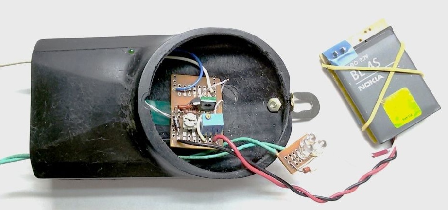
8. If possible, we seal the gaps from dust and moisture.