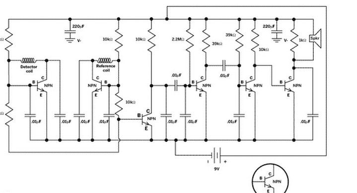
Consider how you can make simple and quite powerful. metal detector based on two interconnected oscillators. One oscillator in this scheme will be fixed, and the other will be dependent on it and its frequency will vary depending on whether there are metal objects nearby or not. Due to the fact that the beat frequency of the oscillators is less than 100 kHz, these beats can be heard in headphones or dynamics. Accordingly, if there is a metal object under the coil, the sound will change.
All types of metals change the frequency differently; they can raise or lower it.
Materials and tools for homemade:
- single-sided copper multilayer printed circuit board with dimensions of 114.3 mm x 155.6 mm;
- five capacitors 0.1μF;
- five capacitors 0.01μF;
- two electrolytic capacitors 220μF;
- PEL type wire with a diameter of 0.4 mm;
- jack for headphones and earphones;
- 9V battery;
- connector for installing the battery;
- switch;
- Six transistors type NPN, 2N3904;
- wire type 22 AWG or cross section - 0.3250 mm2 to connect the sensor;
- wired speaker;
- a small speaker of 8 ohms;
- threaded PVC pipe with a diameter of 1/2;
- wooden dowel size 1/4;
- wooden dowel 3/4 ′;
- wooden dowel 1/2 ′;
- epoxy;
- plywood 1/4 ′;
- carpentry glue.
From the tools:
- 3/4 ″ size drill for cutting holes;
- drill with drills;
- electric iron;
- a hacksaw;
- laser printer;
- an oscilloscope or multimeter with a frequency meter;
- sandpaper and more.
The process of manufacturing a metal detector:
Step one. We make a printed circuit board
The first step is to download the board design:
View online file:
Next, the board needs to be printed and etched on a copper board. The author used a laser printer for such purposes, where then the toner is transferred to the board using an iron. As a result, the toner during etching works like a mask, protecting the metal paths.
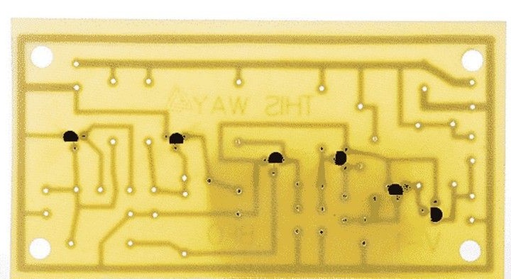
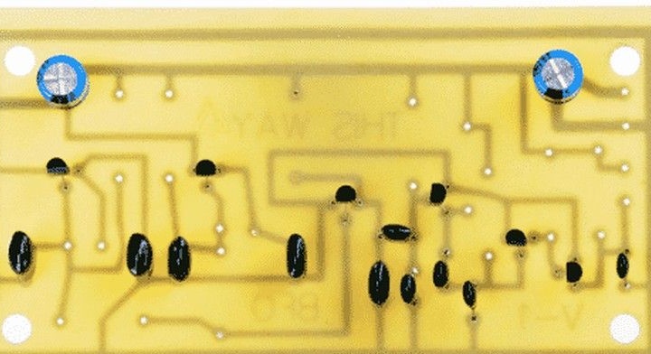
Step Two Assembly. Installation of transistors and electrolytic capacitors
The author began assembling the circuit with the installation of transistors and electrolytic capacitors. First you need to solder six NPN transistors. Here it is important not to confuse and make sure that the legs of the transistor are in place. The base leg is almost always in the middle.Subsequently, you need to solder two electrolytic capacitors with a capacity of 220μF.
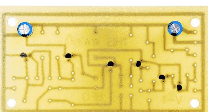
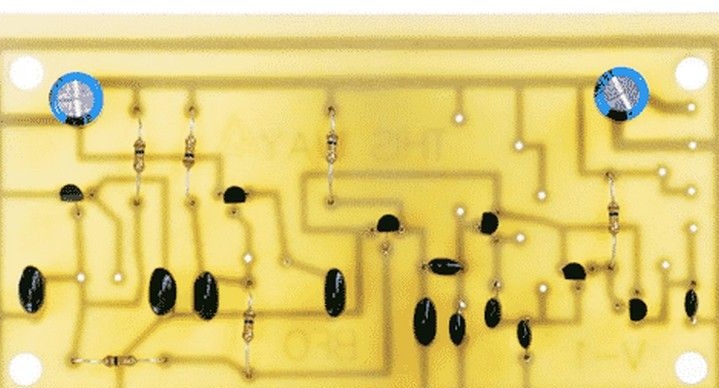
Step Three Polyester Capacitors and Resistors
The next step is the installation of resistors and polyester capacitors. In total, you need to solder the five polyester capacitors with a capacity of 0.1μF in the places indicated in the picture. Then you can solder another 5 capacitors with a capacity of 0.01μF. Due to the fact that polyester capacitors do not have polarity, they can be soldered as you like.
Well, at the conclusion of this step, you need to solder six 10 kΩ resistors. Such a resistor is color-coded - brown, black, orange, gold.
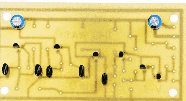
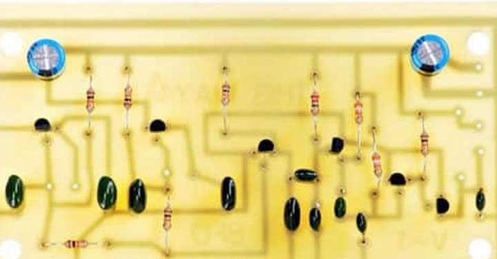
Step Four The final stage of assembly circuit
Filling the circuit with electronic elements is nearing completion. At this stage, you need to install one resistor at 2.2 mOhm (marking - red, red, green, gold) and two at 39 kOhm (marking - orange, white, orange, gold). Well, now it remains to solder the last 1 kΩ resistor, it is marked - brown, black, red, gold.
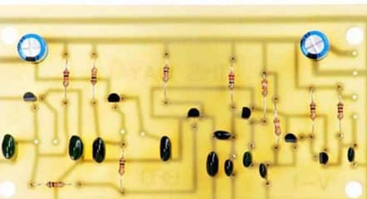
At the conclusion of the assembly of the board, all the necessary wires are soldered to it. For simplicity, it is best to use wires of different colors. A red / black pair was used for power, a green pair for audio output, black for a reference coil, and yellow for a detection coil.
Step Five Collect coils
There are two coils in the metal detector; you need to start assembly from the reference coil. For these purposes, you need a wire 0.4 mm thick. For the base, you need a piece of the dowel about 13 mm in diameter and 50 mm in length. In the dowel, you will need to make three holes, one full-length, and the other two across the edges. A wire will pass through these holes.
Now you can wind the wire. It needs to be wound as much as it fits on the dowel in one layer. At each end, you need to leave a supply of wood 3-4 mm. According to the author, the correct winding of the wire, wrapping it around the dowel, will not work. You need to hold the wire in your hand, and turn the dowel, so the wire will lie on the dowel as evenly as possible.
Each wire will need to be pulled through a perpendicular hole, and then one of the ends through the inner longitudinal. When the coil is fully wound, the winding must be fixed with electrical tape.
It is also important not to forget that the wire is coated with varnish and this coating must be removed before further assembly. It can be burned or cleaned with sandpaper.
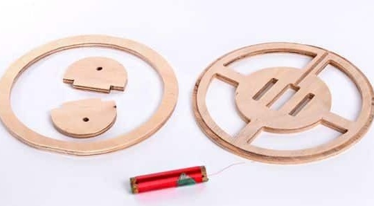
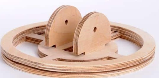
For a search coil, plywood with a thickness of 6-7 mm will be needed, from such plywood a base is made, a body for a future coil. Having made the basis, you need to wind 10 turns of wire with a cross section of 0.4 mm into the groove. The author has a coil diameter of 152 mm.
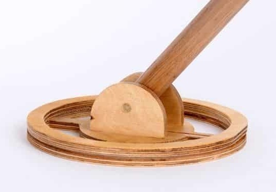
The handle to the holder must be mounted with wood or other non-metal materials, otherwise the metal detector will always show the presence of metal.
The final stage. Customization
At the end, the metal detector must be configured. The essence of tuning is to reach a frequency of not more than 100 kHz on the reference coil. The author used an oscilloscope for such purposes. But if there is none, then a multimeter with a function for determining the frequency is suitable.
To increase the frequency of the coil and reduce the inductance, the coil is shortened. The author managed to achieve a frequency of 100 kHz with a coil length of 31 mm.