
This article will show you how to make it very simple. metal detector from almost improvised materials. Despite its simplicity, the metal detector works, it can find a coin at a depth of 10 cm, a pan at a depth of 30 cm, and the device sees a sewer hatch at a depth of 60 cm. This is certainly not much, but for such a simple device it’s pretty good. However, if you work with him on the beach or just build for informational purposes, then you will not lose time in vain.
Materials and tools for homemade:
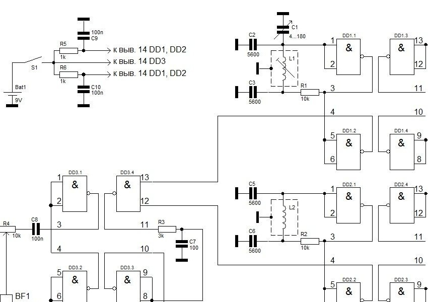
- A complete list of the details of the board can be seen in the diagram, it includes the K176LA7 chip;
- wire for the coil (PEV-2 0.08 ... 0.09 mm);
- armored magnetic circuit;
- epoxy;
- headphones;
- soldering iron with solder;
- materials for creating a rod, body, and so on.
The process of manufacturing a metal detector:
Step one. A few words about the scheme
L1 must be wound on a frame with three sections with a trimming core and placed in an armored magnetic circuit with a diameter of 8.8 mm made of 600NN ferrite. In total, the coil has 200 turns of PEV-2 wire 0.08 ... 0.09 mm.
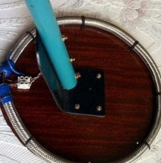
The L2 coil is made from a piece of aluminum tube with a diameter of 6-9 mm and a length of 950 mm. Through it you need to thread 18 pieces of wire with good insulation. Next, the tube must be bent using a mandrel, in diameter it should be about 15 cm. The wire segments are connected in series. The inductance of this kind of coil should be in the range of 350 μH.
The ends of the tube do not need to be closed, but one of them must be connected by a common wire.
For the scheme described above, the author used a rubber hose with a metal base inside, as well as a solid wire, varnished. In order not to damage the insulation, tweezers with rubber tubes at the ends were used. The winding must be fixed as carefully as possible, otherwise the device will give false positives.
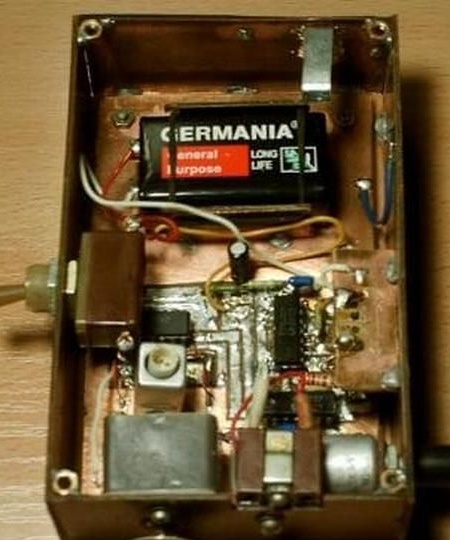
Well, then the board is placed in a metal, but not magnetic case.
It is important to note the fact that the cable going from the board to the coil must be shielded.
Step Two Further assembly and configuration
To adjust the capacitor knob, you need to turn it to the middle position, and then by rotating the tuning core L1, you need to ensure that there are no beats in the headphones. The setting will be correct if a buzz is heard in the headphones when you turn the variable capacitor knob a small angle.
The adjustment is carried out at a distance of at least one meter from massive metal objects.
The author was able to increase the sensitivity of the device if the core of the tuning coil was screwed to the stop, and by adjusting the settings using an alternating capacitor to achieve almost complete absence of sound in the headphones. At the same time, if you turn on the headphones at full power, the sound will be quiet.
If it is so that the sound in the headphones is not heard at all, it is necessary to check the presence of a U-shaped signal at pins 4 DD1 and DD2, for such purposes an oscilloscope will be needed. At pin 11 and 8, DD3 should be a mixture of signals.
It should also be noted that the original circuit indicates a resistance of R3 300 kOhm, but the headphones will not work with such resistance. It needs to be replaced with 3 kOhm. Instead of 5600 pF capacitors, the author also used at 4700 pF, since the first could not be found.
The disadvantages of the circuit include the fact that the chamber is sensitive to ambient temperature, in this regard, the device must be constantly tuned with a variable capacitor, achieving zero beats.
Step three. The final stage of assembly
The author recommends filling the coil with epoxy, this will allow you to securely fix the wires. Otherwise, there will inevitably be false positives, since in the search process you have to touch stones, sticks and other obstacles, moreover, the coil can be easily damaged. Instead of epoxy, wax or plasticine is suitable, which must be melted and filled. Paraffin should not be used, since it becomes brittle after solidification and does not have elasticity. If the choice fell on plasticine, then you need to make sure that it does not leak out, warming up in the sun.
Among other things, in the circuit, gently replace the resistor R3, its rating should be 300 kOhm. You also need to adjust the frequency of the model generator so that confident and clear clicks are heard in the headphones. The sensitivity of the device is determined by the frequency of clicks, the lower it is, the better. With these settings, the author finds a penny coin of the USSR at a depth of 10 cm, which lies horizontally.
If you make the click frequency high, then the presence of metal under the search coil can be determined by the change in sound.
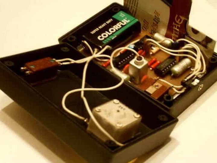
The author also collected another such device and he found a problem - the lack of sound in the headphones. The solution was to remove the capacitor C7 from the circuit. The author also removed the volume control, as the sound itself became quieter. With such refinement, the device did not lose sensitivity.
A case for a device made of plastic can be bought at a radio store; it cost the author 31 rubles. To shield the scheme from cardboard, you need to cut the “shirt” and wrap it with foil. The edges of the foil are attached to the cardboard with tape, then with the help of a stapler a wire is attached and connected to the minus.
Also, an electrolytic capacitor of 47-100 microfarads must be installed in the circuit after turning on the power with a voltage of at least 10V.
To create L2, the author used the wire that he found, it has a diameter of 0.5 mm. A wire of 0.3-0.7 mm is suitable for such purposes. You can conduct experiments with core materials, they can be brass or ferrite.